Rising Star Lightsaber DIY Kit - Build instructions
We have engineered a complete DIY kit to build her/his first collector Lightsaber.
A Padawan Lightsaber and blade, specifically made to be easy and secure to use. It all started when our 5yo son asked for his first lightsaber for his next Birthday, fast forward several month of design, engineering and testing, he finally got what he wanted and was super happy about it. But more importantly for us, it took him only a few minutes to learn how to use and enjoy playing! Mission accomplished!!
Follow this page instructions to learn how to build it yourself, it's a fun project and a happy outcome guaranteed.
The tools needed for this upgrade are the same as any other saber build. If you are unfamiliar with this, consult our Padawan tutorial page for more details.
Rising Star DIY Kit: available on The Kyber Temple
Not fancying any DIY? We have them already built as well and ready to play: also available on The Kyber Temple
Demo


Table of content:
- Build timelapse video – Shows the full install process
- DIY Kit Checklist – to check what you’ve received
- Chapter 1 – Wiring Diagrams
- Chapter 2 – Rising Star Core Install
- Chapter 3 – Hilt install
- Chapter 4 – Charger / Setup Module Install
- Chapter 5 – Blade Install
- Soundboard controls – Learn more about Proffieboard V2.2
- Soundboard setup – SD Card and setup files
- Recommendations and troubleshooting – Must read
Introduction
-
Disclaimer
GOTH-3Designs cannot be held responsible for any mistakes made by DIYers during their install. You must have a good understanding of what you’re doing, of the components used and the safety measures associated to them. Always wear protective gear when working on install (gloves, eye protection, …), GOTH-3Designs cannot be held responsible in case of accident.
-
Note #1
Experience in soldering, assembling model kits, … etc is highly recommended. If you are unsure what to do after viewing these instructions, we recommend that you contact an installer in your region is order to do the install job for you. We can provide a list of contacts for that purpose.
-
Note #2
Always test your install along the way! Verifying that everything works after important steps is better than having to dismount everything because something wasn’t wired properly.
-
Note #3
3D printed parts can have very slight accuracy variations. In some rare cases, some sanding or hole deburring can be required.
Video – Installation Timelapse
DIY Kit Checklist
-
Check that the following components are present in the DIY kit package.
(Contact us if you see any issues with your kit)- Blade Kit:
Polycarbonate tube
Foam diffusion tube
Blade tip
Blade socket
Connector PCB
Blade ID Resistor (4,7K ohm)
Flexible thin NPXL strip
- Battery Charger / Soundboard Setup combo connector:
2 x Chassis Parts
USB-C plug
Battery charge control PCB
Charge LED Indicator
Connector PCB
Blade ID Resistor (33K ohm)
4 x M2 screws and nuts
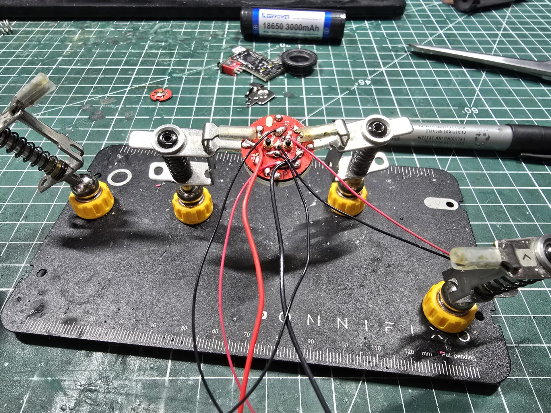
- Emitter connector:
Connector holder
Clear cap
Connector Pixel PCB
14 x Pogo-pins (come already inserted into the connector PCB)
2 x M1.6 screws and nuts
2 x Springs
- Main chassis:
3 x chassis parts
5 x M2 screws and nuts
- Electronic components
18650 Keepower Battery with 15A discharge protection
Kill Switch
Main Switch
Micro-USB Port
Battery holder tabs (positive = button tab, negative = flat tab)
Proffieboard v2.2 Soundboard
22mm Bass Speaker
- PTFE Wires:
22AWG for battery pos and neg, and NPXL pos and Neg.
28 AWG for the speaker
30 AWG for the rest
- 3D printed tool to unscrew the hilt switch

- OPTIONAL: 3D Printed Sleeve

- Blade Kit:


Chapter 1 – Wiring Diagrams
-
Plan ahead the wiring and understand the install perfectly before starting. Here is a Proffieboard wiring example that matches the config loaded on the Proffie and SD Card.
Wire gauge reminder:
22AWG for battery pos and neg, and NPXL pos and Neg.
28 AWG for the speaker
30 AWG for the restThe soundboard is installed with the USB port facing up, and oriented toward the pommel. The board image bellow will simulate how you would look at the board while wiring it and the direction taken by the wires:

USB-C Charger / Setup Module

Blade


Chapter 2 – Rising Star Core Install
-
This is a relatively easy install.
The most important point is to properly manage the wires coming from the emitter connector, in order to allow the spring loaded twist blade lock to work properly.Step 1 – Insert the 5 screw nuts into the chassis using the soldering iron to melt them in.


Proceed slowly and make sure the nuts are flush and flat.
Once done, test them by screwing the 2 other chassis parts in. Do not overtighten the screws.
Step 2 – Insert the 14 pins (if not already delivered inserted).

The clear cap can help the pin proper alignment.
Step 3 – Attach the clear cap using the M1.6 screws and nuts.


Make sure the screws are not sticking out the cap.

Test fit the connector into the holder.
Step 4 – Solder the pins and connector wires (referring to the wiring diagram).


Step 5 – Insert and glue the connector into its holder. Place drops of glue (E6000) or equivalent inside the holder, then press the connector in.


Make sure the connector is well flush and secured
Adding a heatshrink tube to secure the wires helps keep them in place, as shown:
Step 6 – Wire and glue the switch PCB in its slot


Step 7 – Add the springs on the connector holder and insert it in the main chassis.


Test the spring loaded mech using the charger part with its PCB.

Step 8 – Next is the positive battery tab installation.
The positive wire coming from the emitter connector is cut and soldered to another another positive wire which will go to the soundboard.

Solder the wires to the battery tab as shown, then start by inserting the tab into its chassis slot, followed by the connector.

Test the spring loaded mech again.

Step 9 – Manage the wires, by splitting them to go on both sides of the switch slot. Check the diagram to see which side each wire should go to.


Press the wires on each side, as shown and check that the cover fits flush without difficulties

Step 10 – Wire the negative battery tab and insert it in its main chassis slot.


Note that the tab should be expanded a bit to give more pressure to the battery and avoid unwanted power cut when dueling hard with the saber.
Step 11 – Next is the kill switch install.
Check the negative wire length necessary to reach the switch. Cut the wire and solder it on the switch, middle position.

Solder the second wire on the left position, as shown, then place back the switch in its slot.

Step 12 – Wire and install the speaker in its slot (28 AWG wires are used here).


Add the cap and screw it on the main chassis.

Add the hilt pommel and check that the on/off pommel twist works fine.
Step 13 – Wire the Micro-USB plug

Step 14 – Wire the soundboard

Tip for the NPXL Negative wire, that needs to bridge 2 pads on the soundboard. Insert it as shown then bend it to the second pad (cut at the right length), then solder the wire on both pads.

Put the soundboard in its slot and test

Step 15 – Insert the Micro-USB plug and solder the last wire to the positive pad as shown


Step 16 – Glue the soundboard in its slot (optional) and add screw the cover on the main chassis.


Once the blade is ready, test the core and blade.


Chapter 3 – Hilt install
-
Step 1 – Check that the switch hole and shroud are well aligned (test by screwing the switch in). Then glue the switch bezel on the shroud.

Step 2 – Push the chassis inside the hilt, with the chassis switch rotated 90 degrees clockwise from the hilt switch hole position.


Then rotate the chassis using the pommel to align the sitch and hole.
Step 3 – OPTIONAL – Add the 3D printed grip. Push the hilt into the grip (it’s press fit) until the right position.


Step 4 – Screw the switch plunger assembly to lock everything.


Chapter 4 – Charger / Setup Module Install
-
Step 1 – insert the 4 nuts in the chassis.

Step 2 – Replace the LED indicators on the controller PCB by the bi-color LED


Step 3 – Wire the USB-C port, then glue it on the chassis


Also insert the charge controller PCB in its slot
Step 4 – Wire and glue the connector PCB in its chassis slot


Step 5 – Assemble the module with the screws, then test it.
The battery will charge when plugged in and the hilt is turned off.

The soundboard setup (and SD card access) can be done when the hilt is turned on.


Chapter 5 – Blade Install
-
Step 0 – Cut the polycarbonate tube to 69cm approx

Step 1 – Stick the 2 strips back to back.
Optional – a rigid flat stick can be added in between the 2 strip to make the build easier (such as the insertion into the foam tube for example)

Step 2 – Wire the 2 strips.
Optional – heatshrink tubing can help securing the wires

Step 3 – Wire the connector PCB (and Blade ID Resistor)


Step 4 – Optional – add clear gift wrap to help light diffusion.

Step 5 – Insert the strips assembly into the blade socket and foam tube, then glue the PCB in its slot on the blade socket.


Step 6 – Optional – sand the polycarbonate tube (with 1000 grit sandpaper) to help light diffusion

Step 7 – Insert the assembly into the polycarbonate tube.

Step 8 – Once the blade tested with the chassis core, glue the blade socket and tip


Congratulations for completing this guide!
Find below further instructions on how to control the soundboard:
Main Button Controls
-
1 Button Controls
Terminology:
Click = do short click (so Double Click is two short clicks in quick succession)
Long Click = hold button for 1 second and release
Hold = hold button down
Click and Hold = hold on Xth click (so Double Click and Hold would be click twice and hold on second click)
Click + Long Click = do X clicks then do long click (so Double Click + Long Click would be click twice then do a long click)
Clash = hit the saber
Hold + Clash = hit the saber while holding the main buttonStandard Controls While Blade is OFF
- Turn On / Ignite Saber* = Click
*If the saber has not been used for a while (asleep) first Click will Wake up motion detection and boot sound will play - Turn On / Ignite Saber (Muted) = Click + Long Click
- Start / Stop Music Tracks = Double Click (pointing straight up)
- Track Player = Double Click (parallel or down)
Turn Right (Stepped) = Next Track
Turn Left (Stepped) = Previous Track
Click button = Play Current Track Once
Hold button = Random (will play current track and then randomly select next tracks)
Hold button + Turn Right = Rotate (will play current track and then next sequential tracks)
Hold button + Turn Left = Loop Current Track - Force/Quote Player – Triple Click
If quotes exist in current font pointing straight down will toggle between Force/Quote and play
*Quotes play sequentially 1,2,3…
If parallel will do Force/Quote based on current mode
Special Abilities (Style Controlled) (requires FETT263_SPECIAL_ABILITIES)
Hold PWR + Turn Right (parallel or up) = Special Ability 5 (USER5)
Hold PWR + Turn Left (parallel or up) = Special Ability 6 (USER6)
Hold PWR + Turn Right (pointing down) = Special Ability 7 (USER7)
Hold PWR + Turn Left (pointing down) = Special Ability 8 (USER8) - Next Preset = Long Click (parallel or up)
- Previous Preset = Long Click (pointing down)
- Scroll Presets (using twist menu) = Hold
Turn Right (Stepped) = Next Preset
Turn Left (Stepped) = Previous Preset
Click button = Select Preset
Hold button = Select and Ignite Preset
Long Click button = First Preset - Volume Menu = Hold + Clash (parallel or up)
Turn Right (Stepped) = Increase Volume (to max)
Turn Left (Stepped) = Decrease Volume (to min)
Click button = Exit - Battery Level* = Double Click + Long Click
Point down for volts, parallel or up for percent
Standard Controls While Blade is ON
- Turn Off / Retract Blade = Hold
- Clash Effect = Clash Saber
- Lockup Effect = Hold + Clash
- Lightning Block = Double Click and Hold
- Blast Effect = Click / Double Click / Triple Click
- Multi-Blast Mode = Hold + Swing
Each Swing in Multi-Blast Mode will deflect Blast effect
To exit, click PWR or do Clash - Force/Quote = Long Click
If pointing down will toggle Force/Quote mode and do Force Effect or play Quote accordingly
*Quote plays sequentially
If parallel will do Force/Quote - Stop Track* – Double Click
*if track is playing while ON
To start/select track saber must be OFF
- Turn On / Ignite Saber* = Click
Soundboard Setup
-
ProffieBoard v2.2 Setup
The Proffieboard v2.2 config file can be found on the SD card itself.
Latest config files
ProffieBoardV2-Rising-Star-Prod-V1Proffie OS files (must use this version to update the soundboard setup)
ProffieOSHow to update the Profieboard Config
Please read this page if you want to update your soundboard config using a USB cable:
https://fredrik.hubbe.net/lightsaber/proffieos.html
Recommendations and Troubleshooting
-
Battery handling (for information, using the USB charger is recommended)
– Make sure to always insert the battery in the right way with the positive toward the top / connector PCB (button top battery toward the button pad).
– Switch the soundboard module off (kill switch) while operating the battery.
– In the event the battery is inserted backwards and the soundboard is started, a protection component will fry on the soundboard which will make is inoperative. The soundboard will then have to be replaced.
– Neopixel blade are bright and also power angry. That’s why it is essential to use only protected Li-ion 3.7v batteries with 10A to 15A discharge protection circuit. If you want a second battery, We recommend the same brand as the kit, Keepower.Battery charge
– If the saber sound starts crackling, this means the battery is running out of power.
– If the blade color hue starts to lean toward redish, this also means the battery is running out of power.
– Recharge the battery with a 18650 Li-ion charger. They are easy to find and usually cheap (example)Blade
– The Pixel strip inside the blade can withstand some good amount of dueling, however, it is not planned for sport combat.Known Issues
– Sound freeze, blade effect freeze…: Like any electronic device, bug can happen during usage, but a simple reboot (on/off switch) usually fixes it.
– After intense dueling, the hilt shrouds might become a bit loose.
If it is the case, just unscrew the switch plunger and extract the chassis. Then use the allen wrench included with the hilt to tighten the hidden grub screws (1 screw will lock the upper shroud and 3 screws for the lower shroud)
– After intense dueling or in long term, the 3D printed sleeve might become a bit loose.
The hilt is delivered with the 3D printed grip, and it not glued. It might become a bit loose with intense usage.
Double sided tape would help in this case to avoid the grip to slip away for the hilt.Customer Support
If you have any issues with your build or parts, please contact this email