These designs are no longer supported (FAQ)
(This page is for the 2017 hilt – which is not produced anymore.
New chassis are available for Korbanth/89Saber DV6v2)
Check here
/!\ Important: All DV6 Chassis can be used on the Graflex 2.0 or MPP2.0 with this adapter.
Sith Master Chassis:
3 parts chassis assembly with a distinctive Sith Design. Features MultiBoards Adaptive Chassis to hold all major soundboards currently available, and an innovative 2 parts soundboard cover that slides to give access to the SD card. The Crystal Chamber parts can either be printed in plastic and painted or printed in metal (Brass, Bronze and other precious metals). While being an advanced design, the chassis remains accessible for beginner, thanks to the DV6 being easy to install.
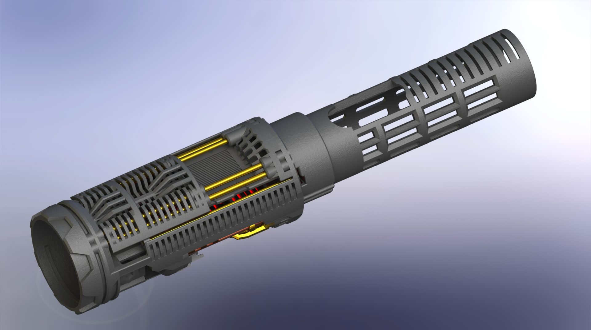
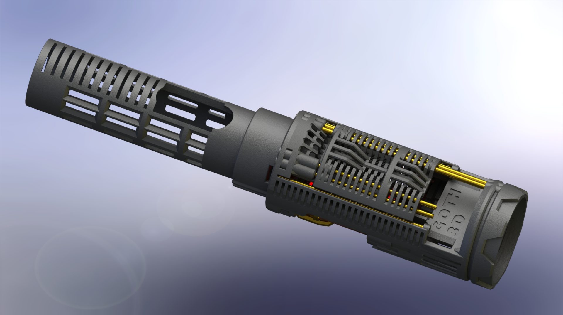
⇒ Part 1 – main chassis: vader-dv6-master-chassis-part-1-main-chassis
⇒ Part 2 – Crystal Chamber Insert 1: vader-dv6-master-chassis-part-2-cc-insert-1
⇒ Part 3 – Crystal Chamber Insert 2: vader-dv6-master-chassis-part-3-cc-insert-2
Optional adapter to use the chassis on a Graflex 2.0: graflex-2-0-adapter-for-dv6-chassis
Additional chassis parts:
Sith Master, here is a list of parts needed to install it:
⇒ Brass or copper rods – 1.5mm max OD
DEMO
DIY INSTRUCTIONS:
Disclainer:
– These instructions will details the install procedure as much as possible. GOTH-3Designs cannot be held responsible for any mistakes made by DIYers.
– Always wear protective gear when working on install (gloves, eye protection, …), GOTH-3Designs cannot be held responsible in case of accident.
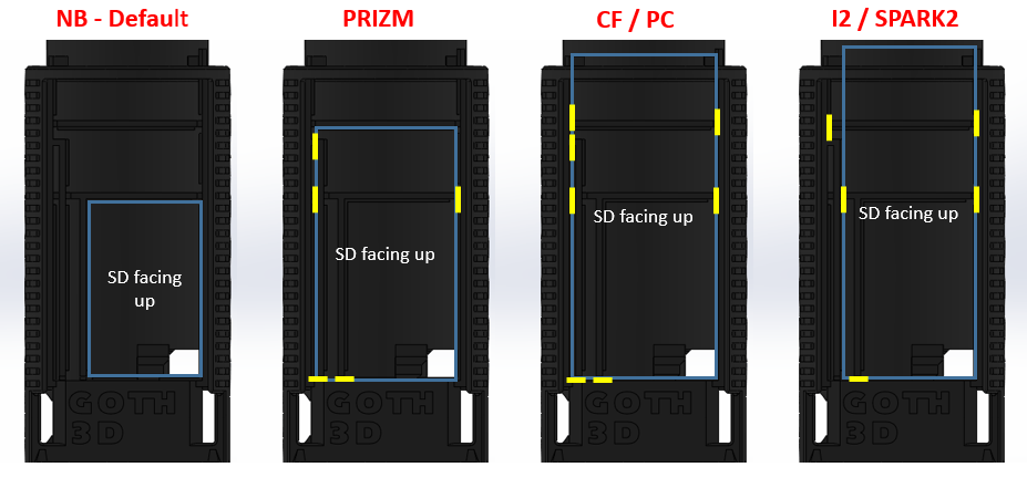
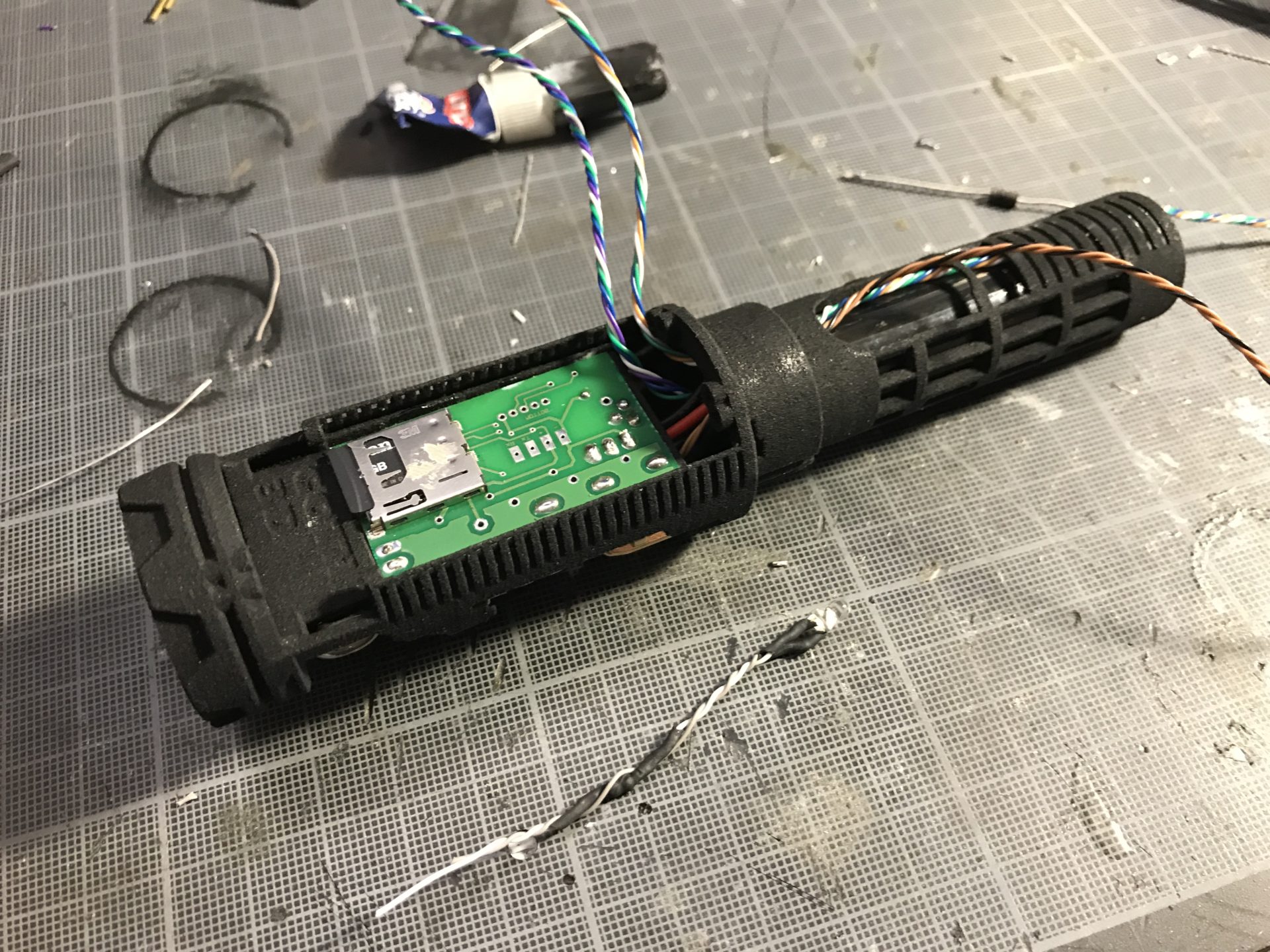
MutliBoards Adaptive Chassis (v1.0) – Gently cut the chassis with an Exacto knife, following the pattern below according to the soundboard you want to install:
UPDATE: Plecter Labs new Prizm 5.1 is smaller than previous versions (4 and 5), you can purchase this adapter piece to make this new board fit into the chassis, after cutting the Prizm pattern shown above.
Note 1: Please read these instructions fully before starting.
Note 2: These instruction will cover the Plecter Labs Prizm 4 install, however the MultiBoards Adaptive Chassis will allow other soundboards to be installed. We do not cover wiring instructions tho, please read your soundboard manual before starting the install.
Note 3: 30awg wires and smaller are mandatory for this install (30awg for main wires and 32awg for accent leds and switches are highly recommended).
Note 4: Thanks to read the full instructions before starting your install. Commission an installer to build the hilt for you, if you feel unsure about what to do.
Note 5: You can always make your chassis original by painting it or adding metal mesh.
Note 6: About the Kill Key. It is recommended to sand a bit the side of the kill key “on/off” slot, in order to make them more round and to turn better in the recharge port. (as a reminder, this slot allow to start / stop the saber without removing the kill key).

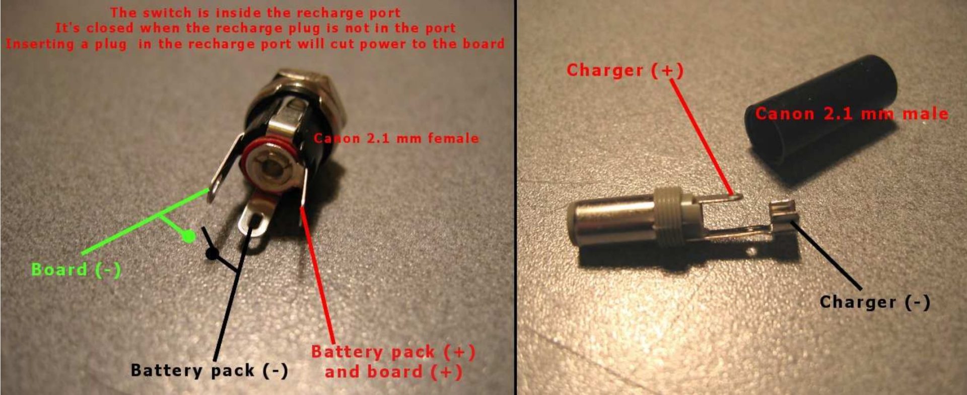
Note 7: Recharge port wiring reminder:
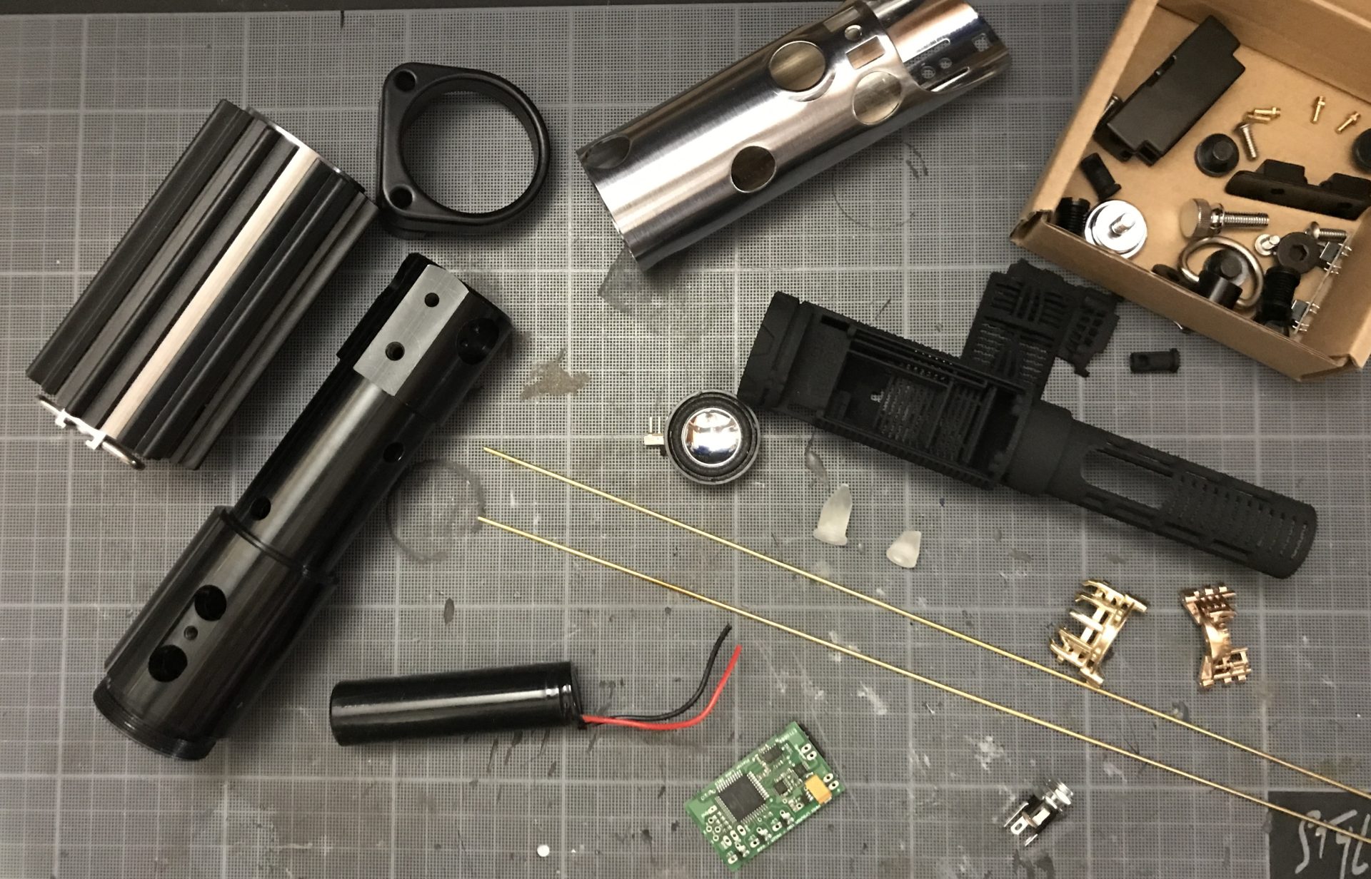
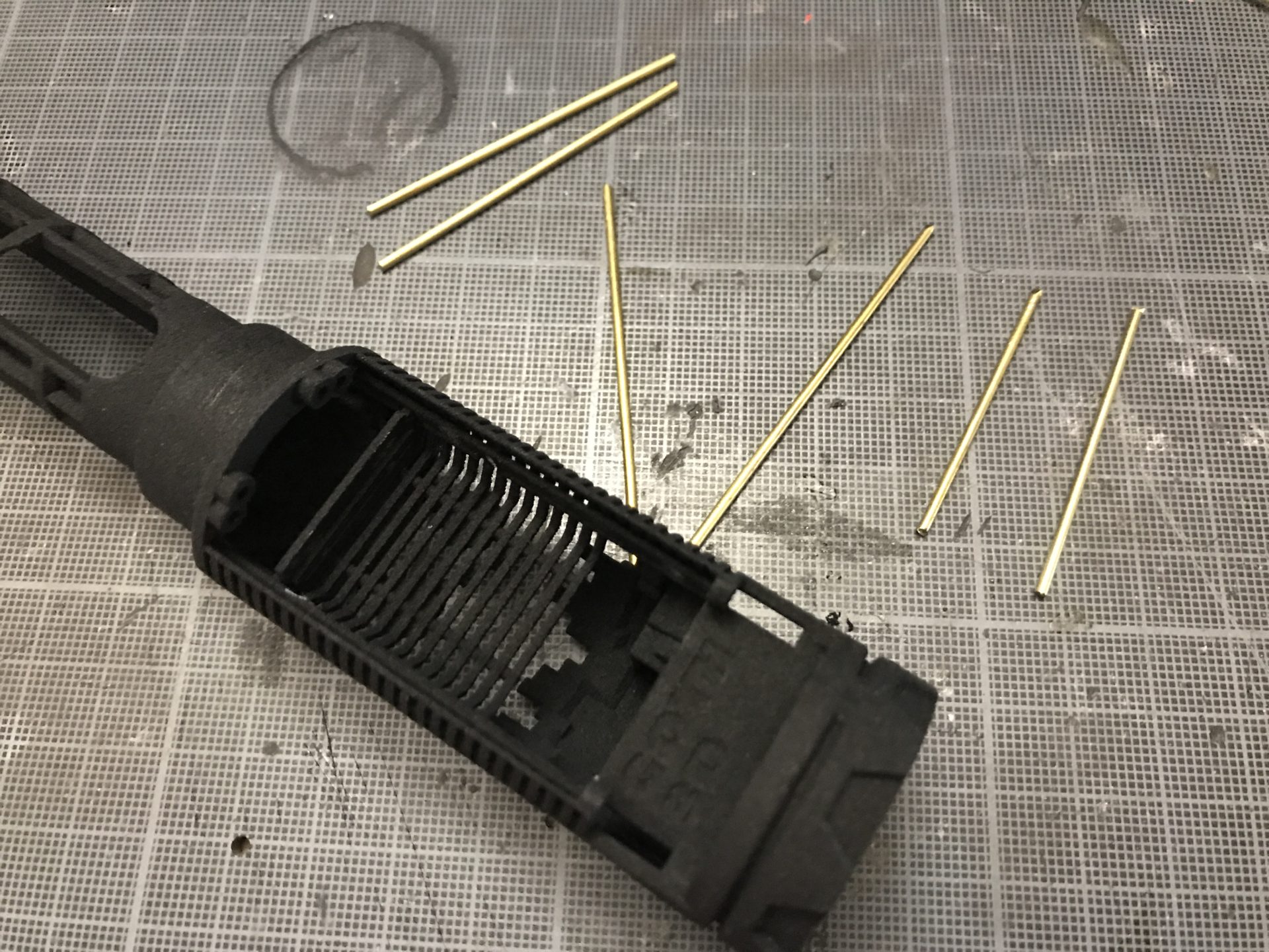
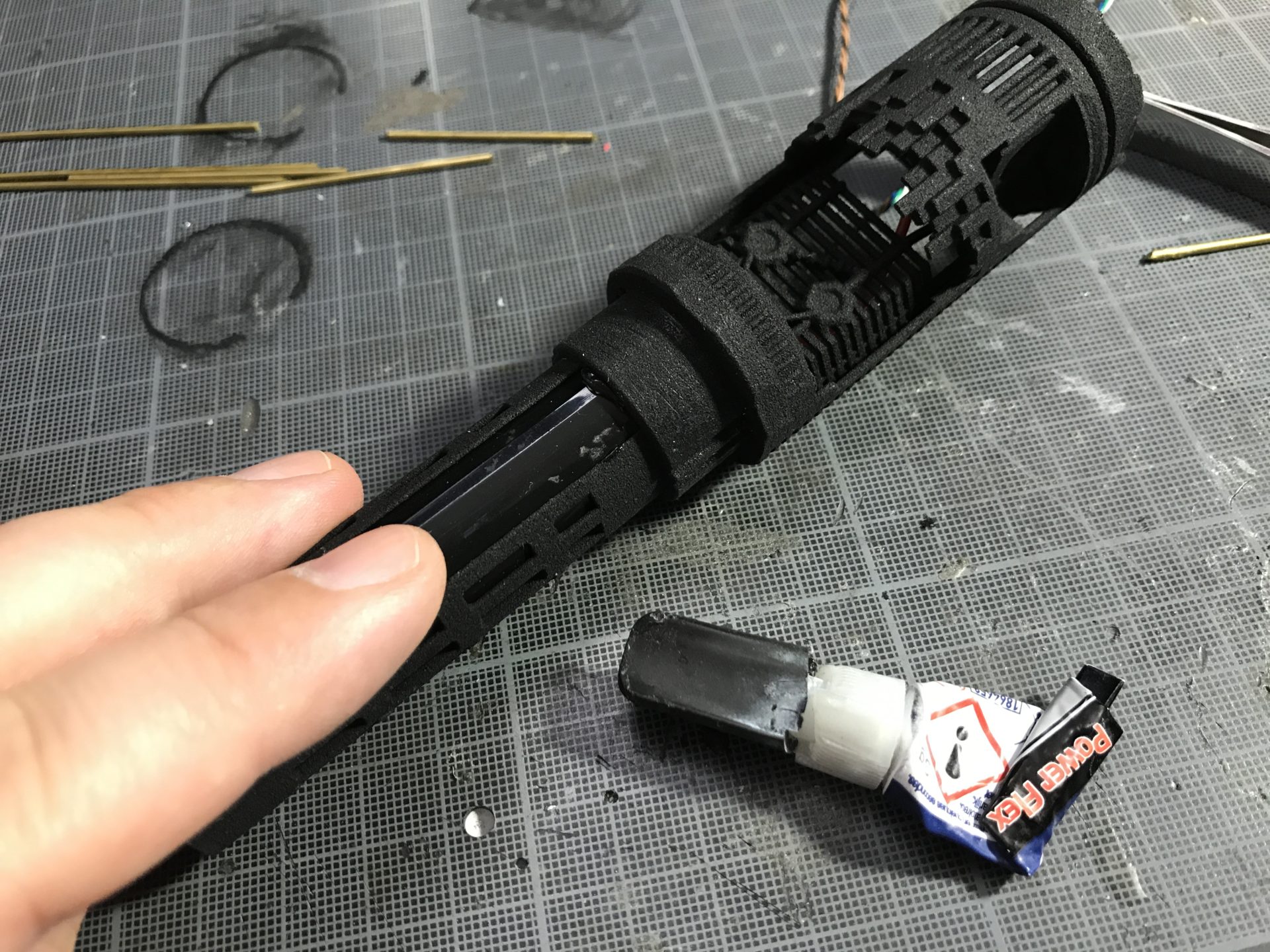
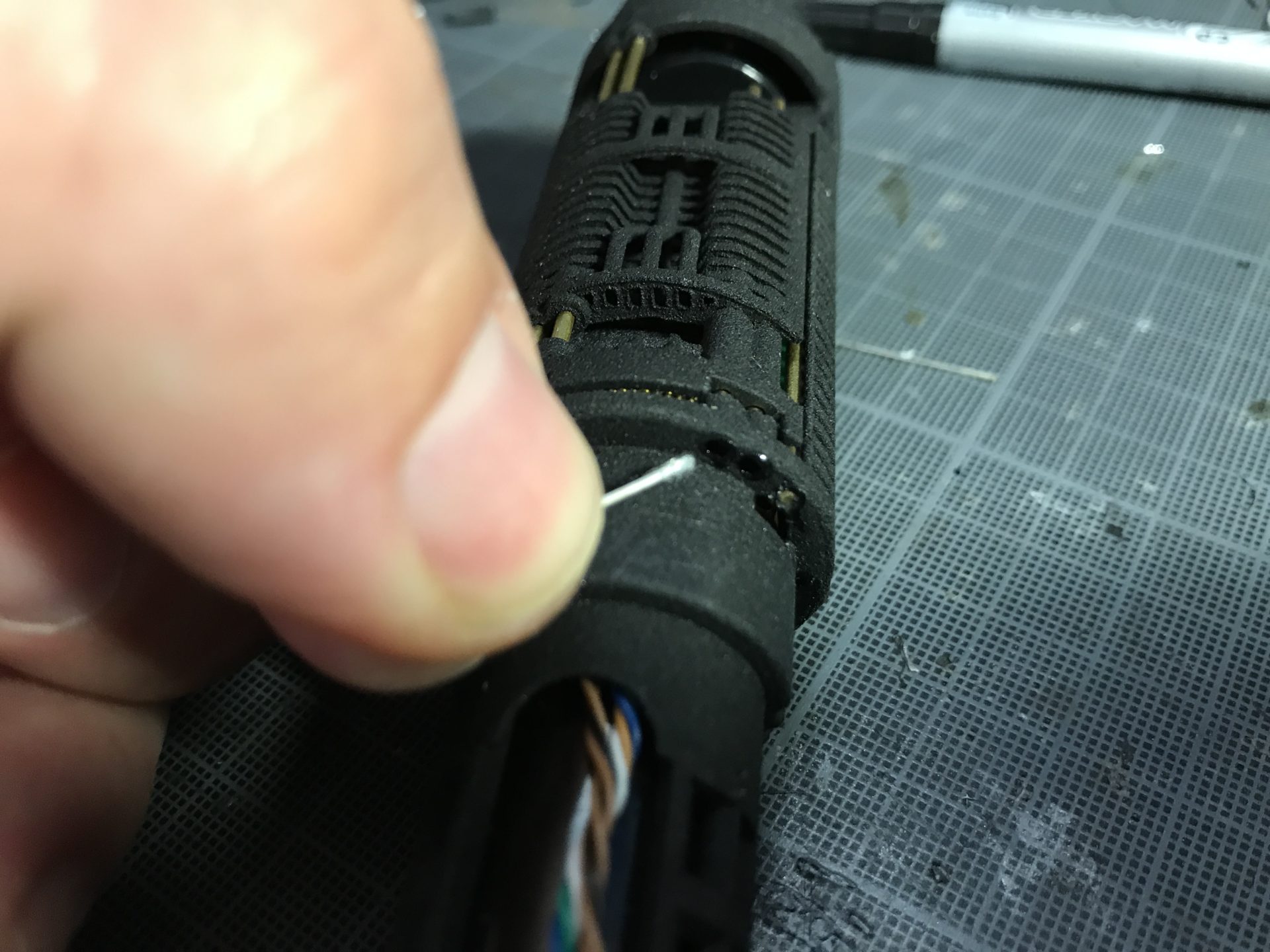
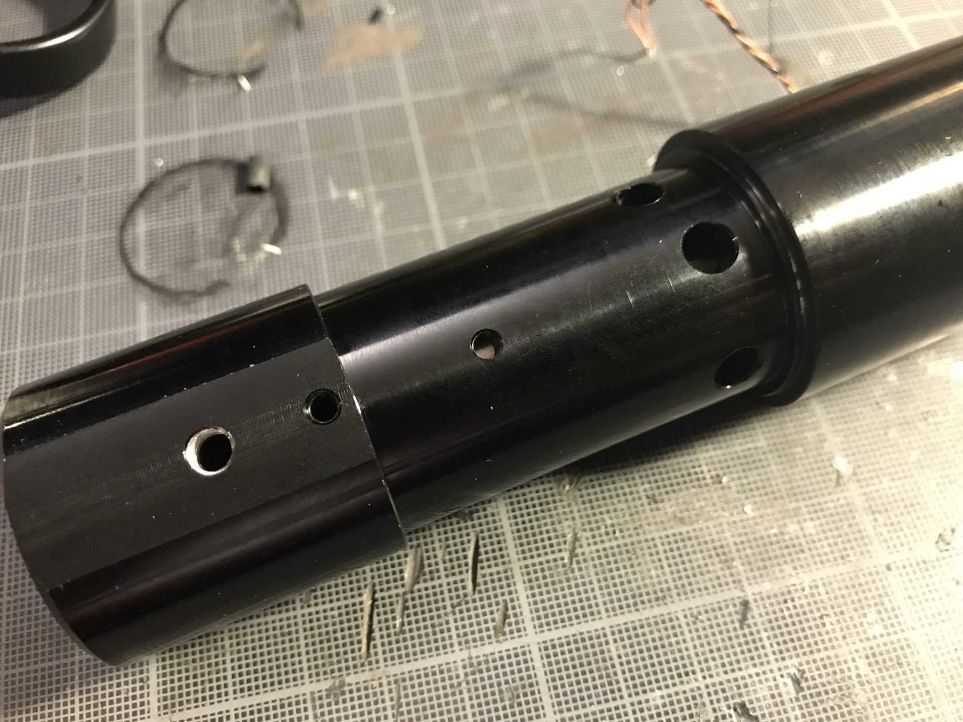
Step 1: Size and cut the 1.5mm OD rods. It might be necessary to clear the hole of printing dust (using a drill bit for example).
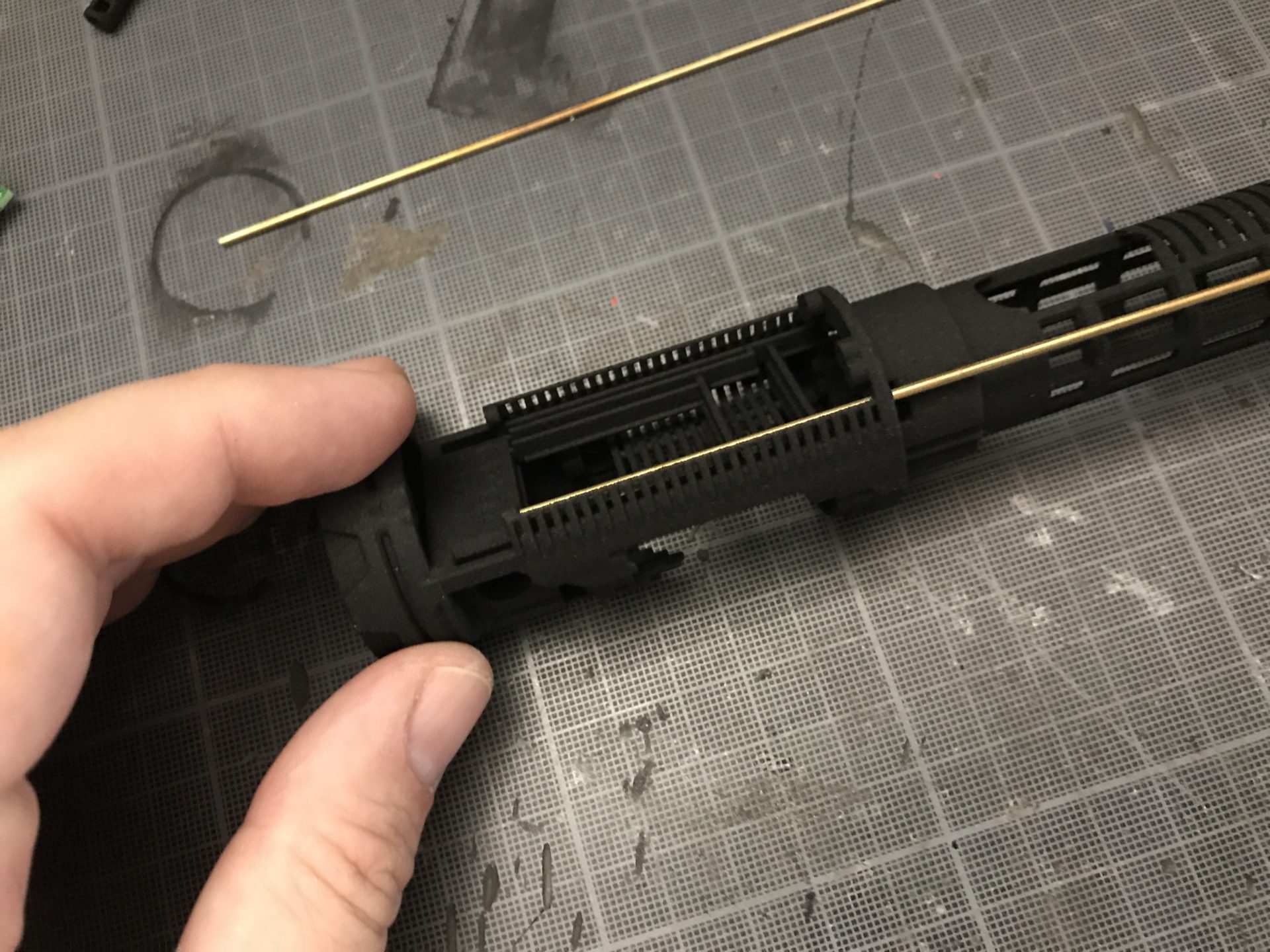
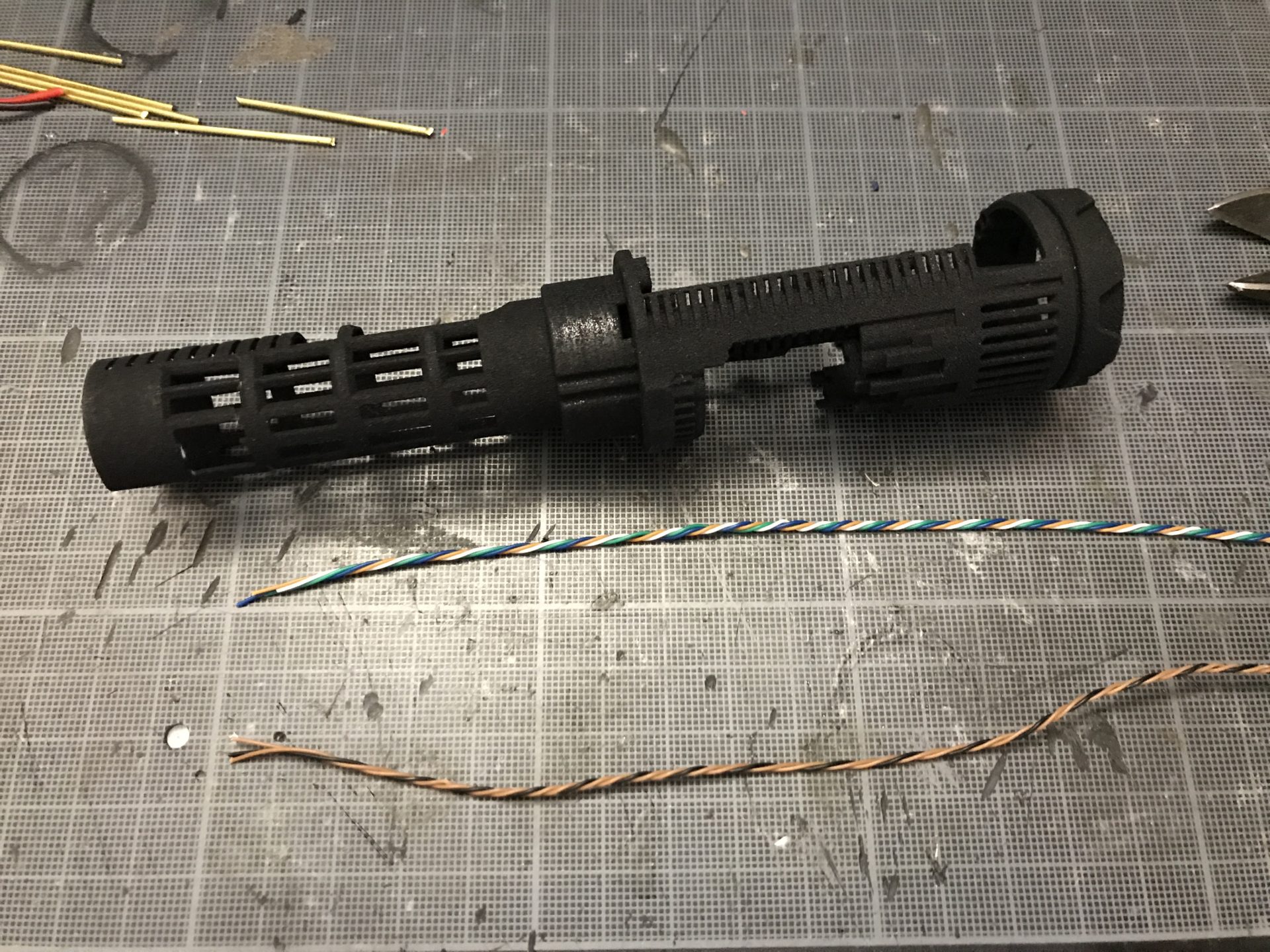
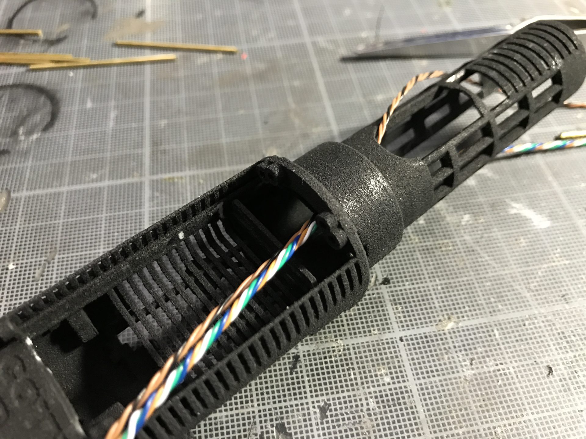
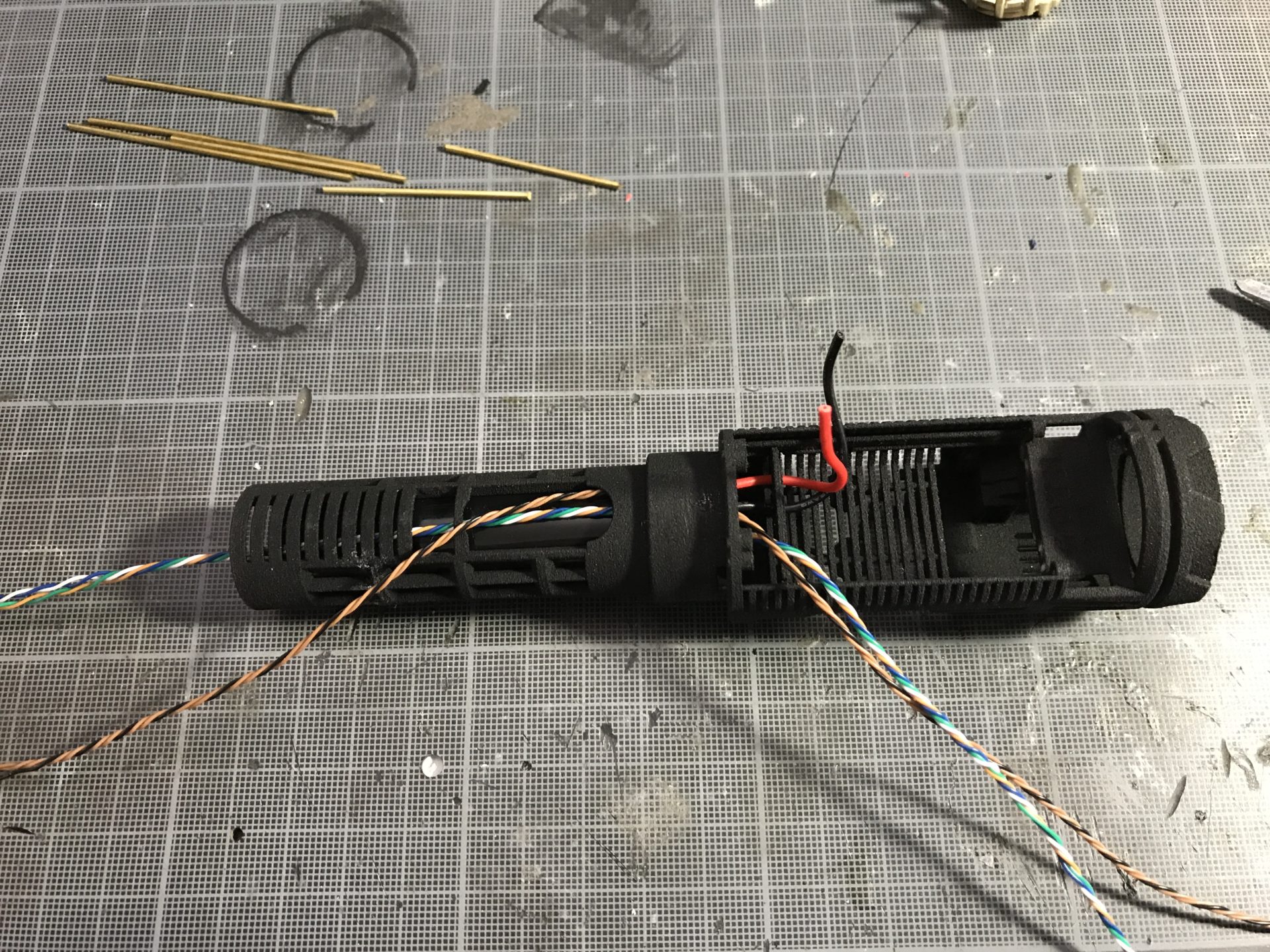
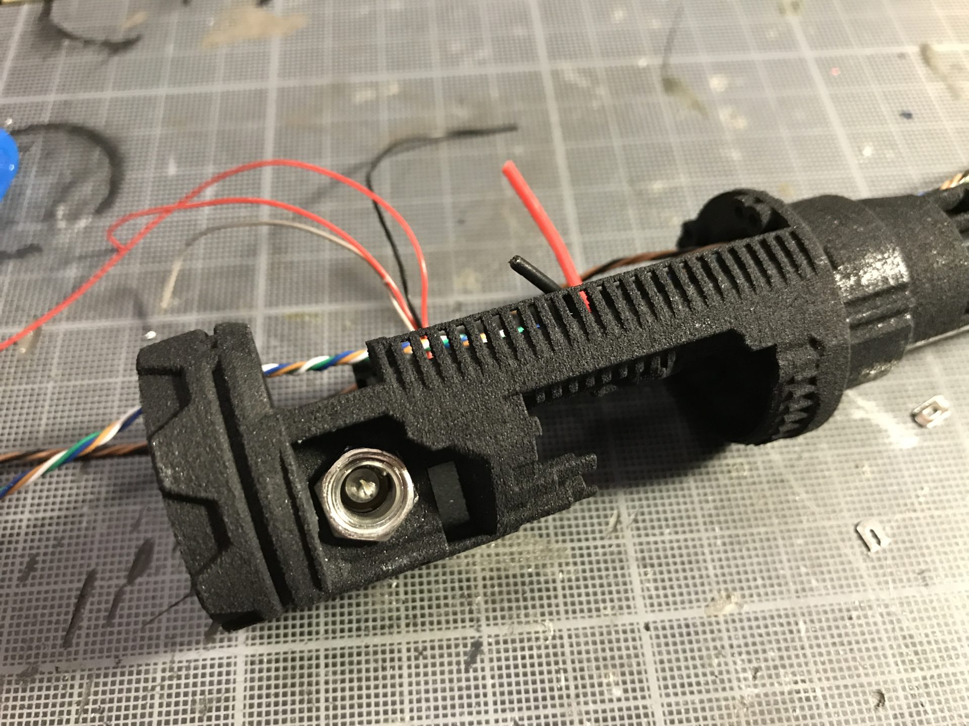
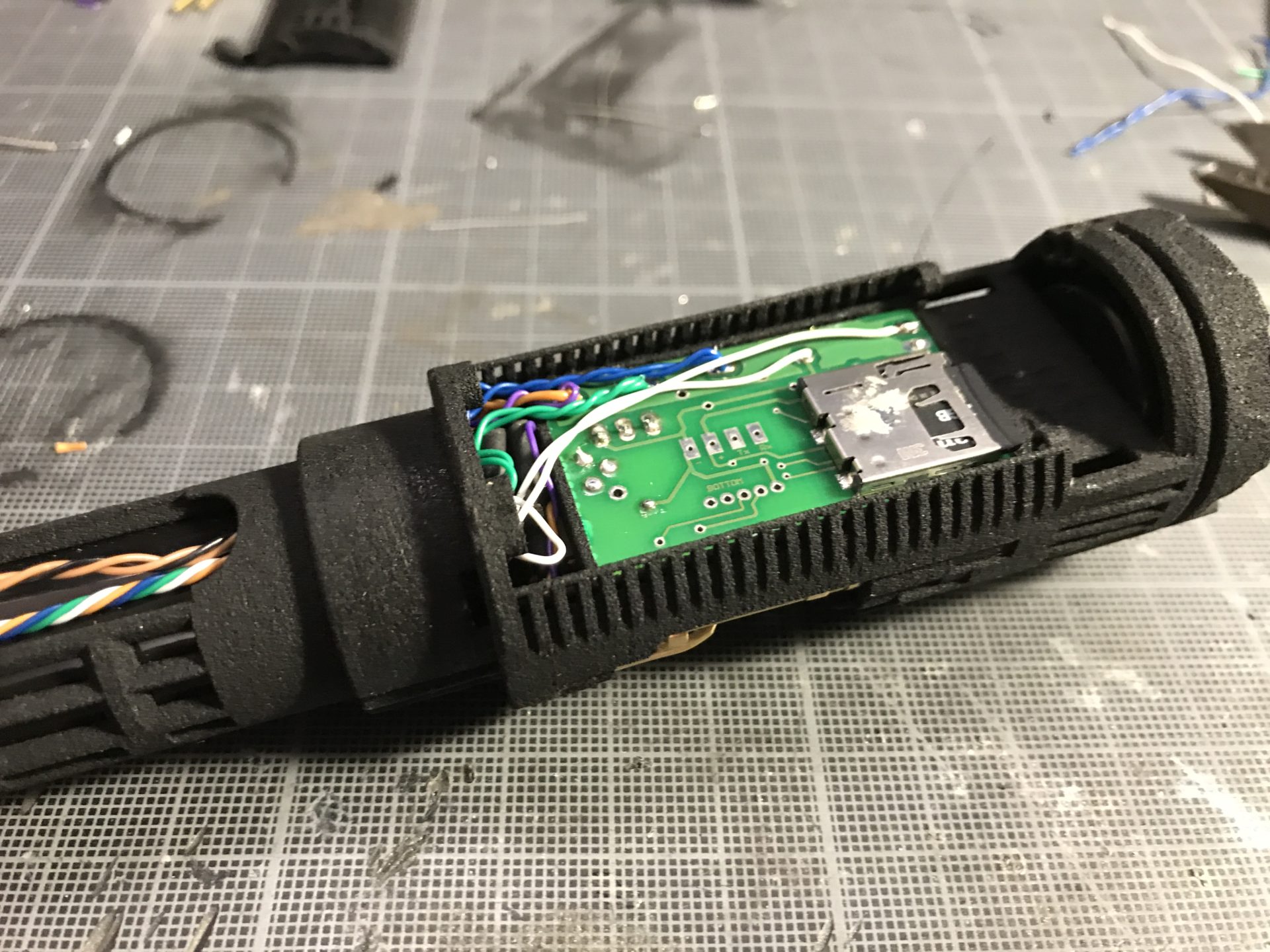
Step 2: Prepare the led and switches wires and pass them through the battery channel. The switches wires exit on the windows shown below.
Step 3: Insert the battery. To secure it, add a tiny bit of Super Glue at the base of the battery holder.
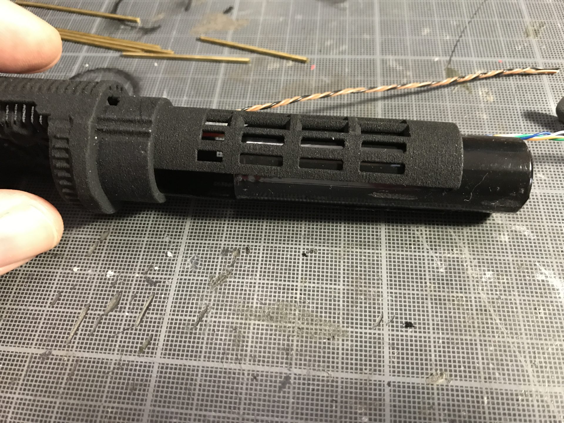
Notes: Make sure the wires can slide and not get blocked.
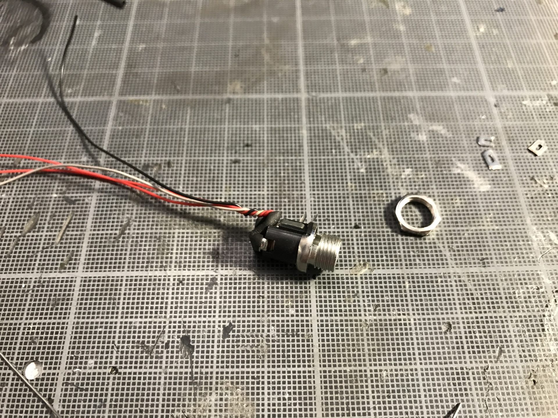
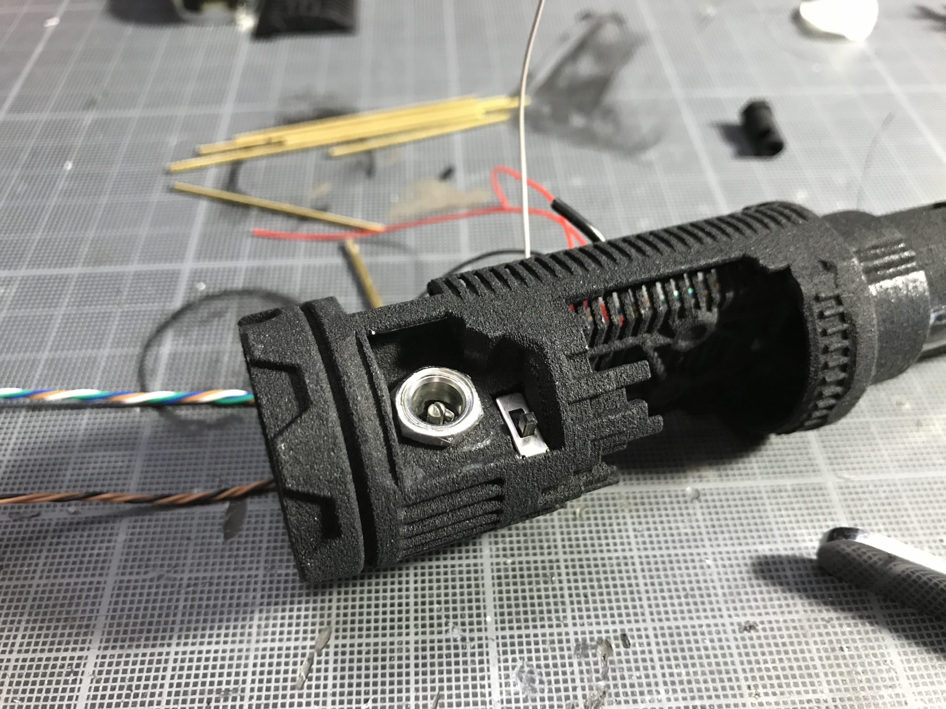
Step 4: Wire the recharge port. The leads have to be cut to their minimum in order to gain space. Test the recharge port fitment by inserting it from outside, clear the hole a bit if required (using hand file or a drill bit).
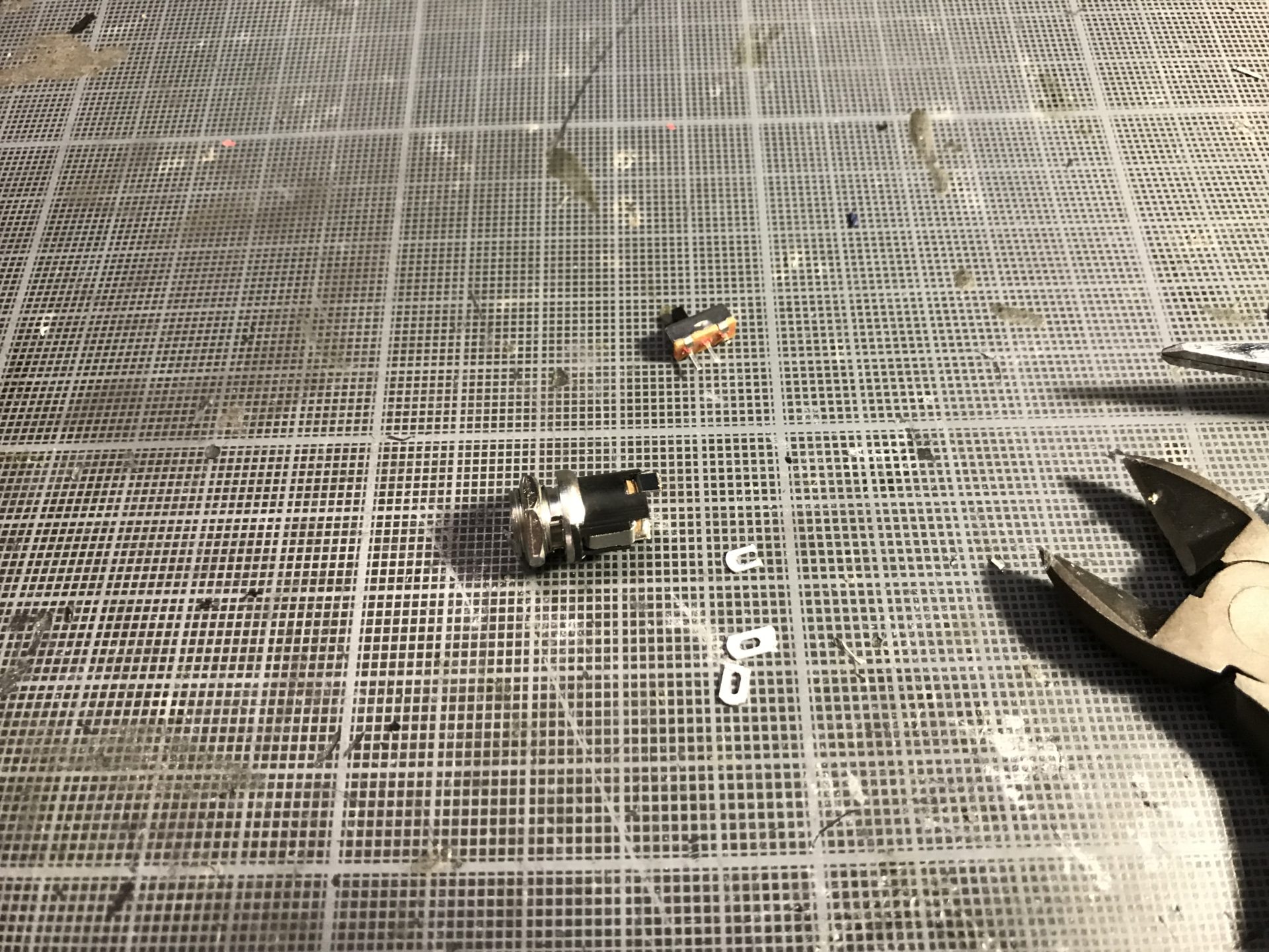
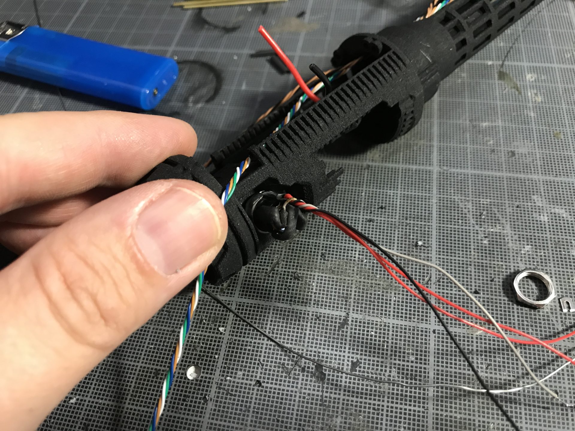
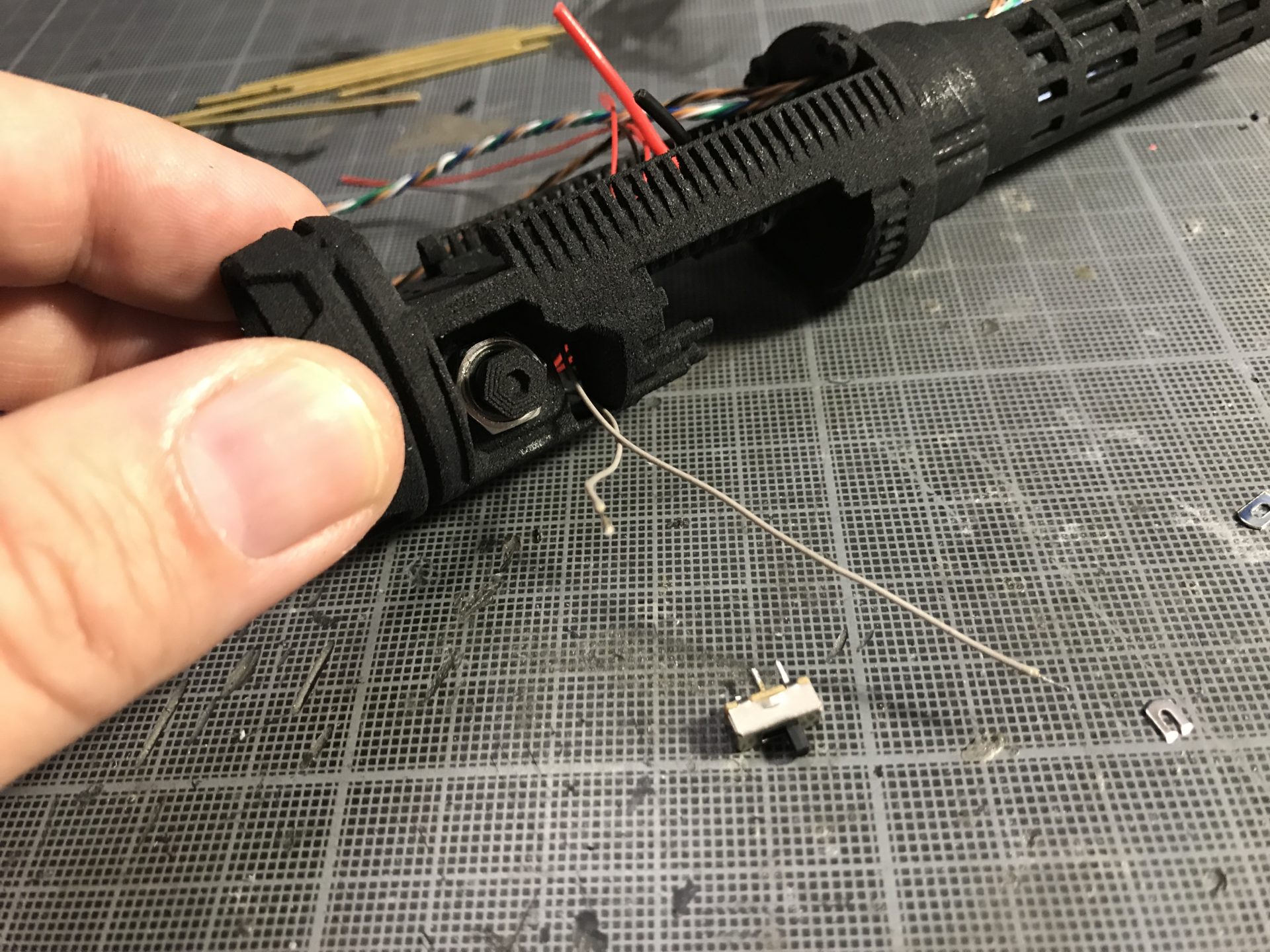
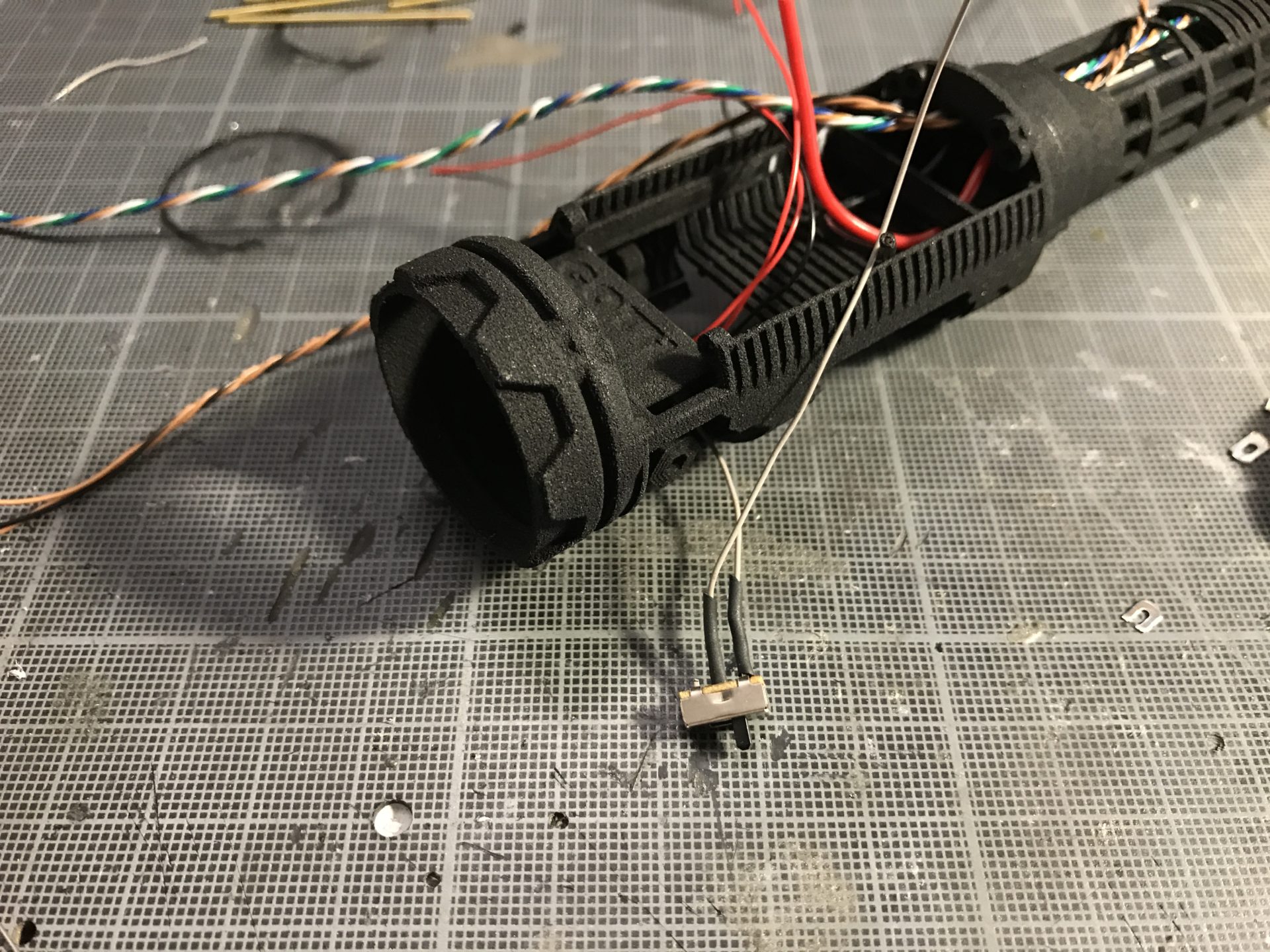
Step 5 (optional): If you don’t want to use the kill key provided with the chassis kit, you can install instead a on/off slider switch (example link under the electronic component section above – Updated the switch slot for a better one / these pictures are made with the old switch).
Step 6: Connect the recharge port wires to the battery.
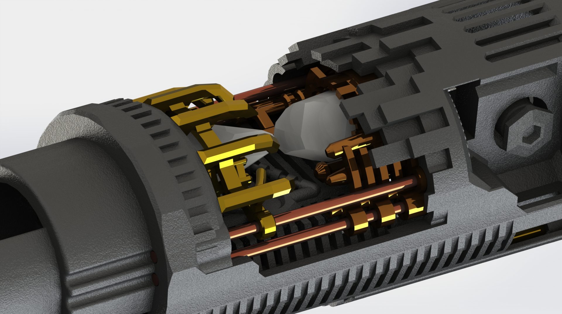
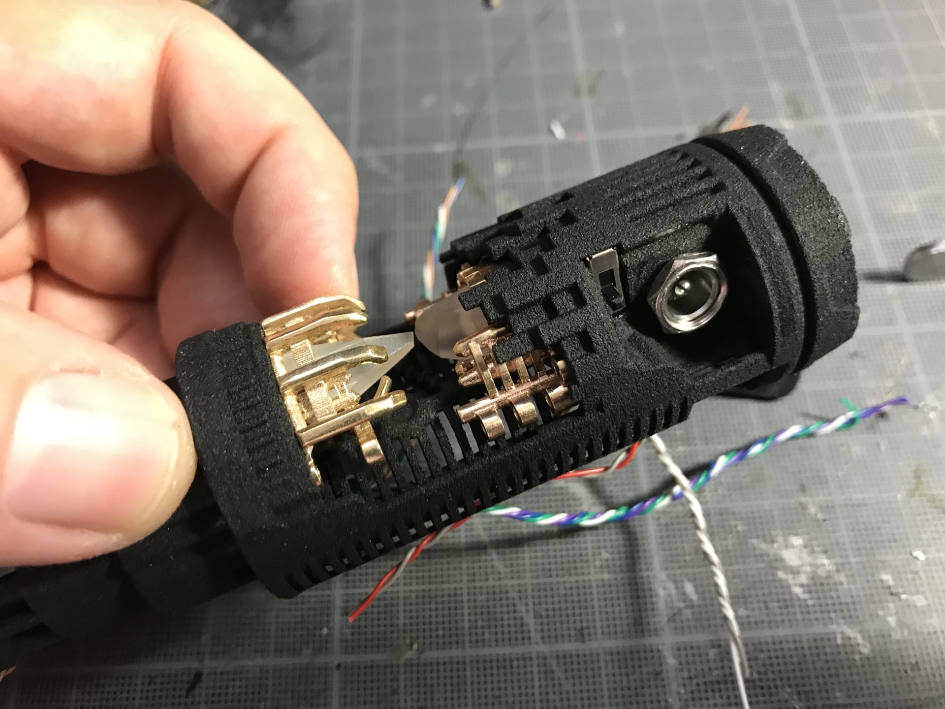
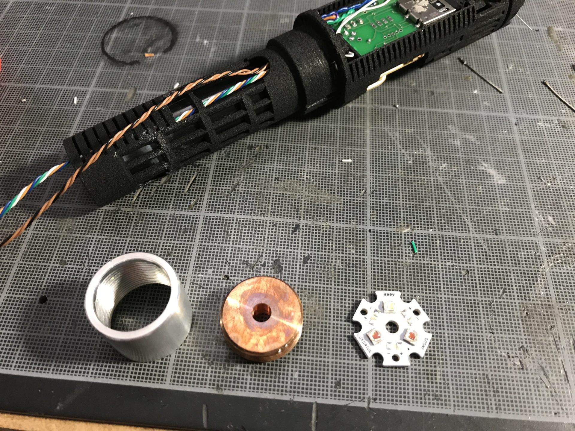
Step 7: Time to prepare the crystal chamber inserts. Start with the CC Insert 2 (Part 3). If you use the optional 3D printed crystal, use the short one, and sand a bit the 5mm led to make it shorter.
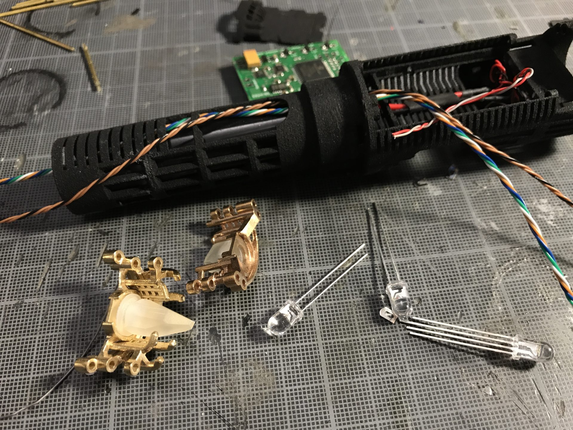
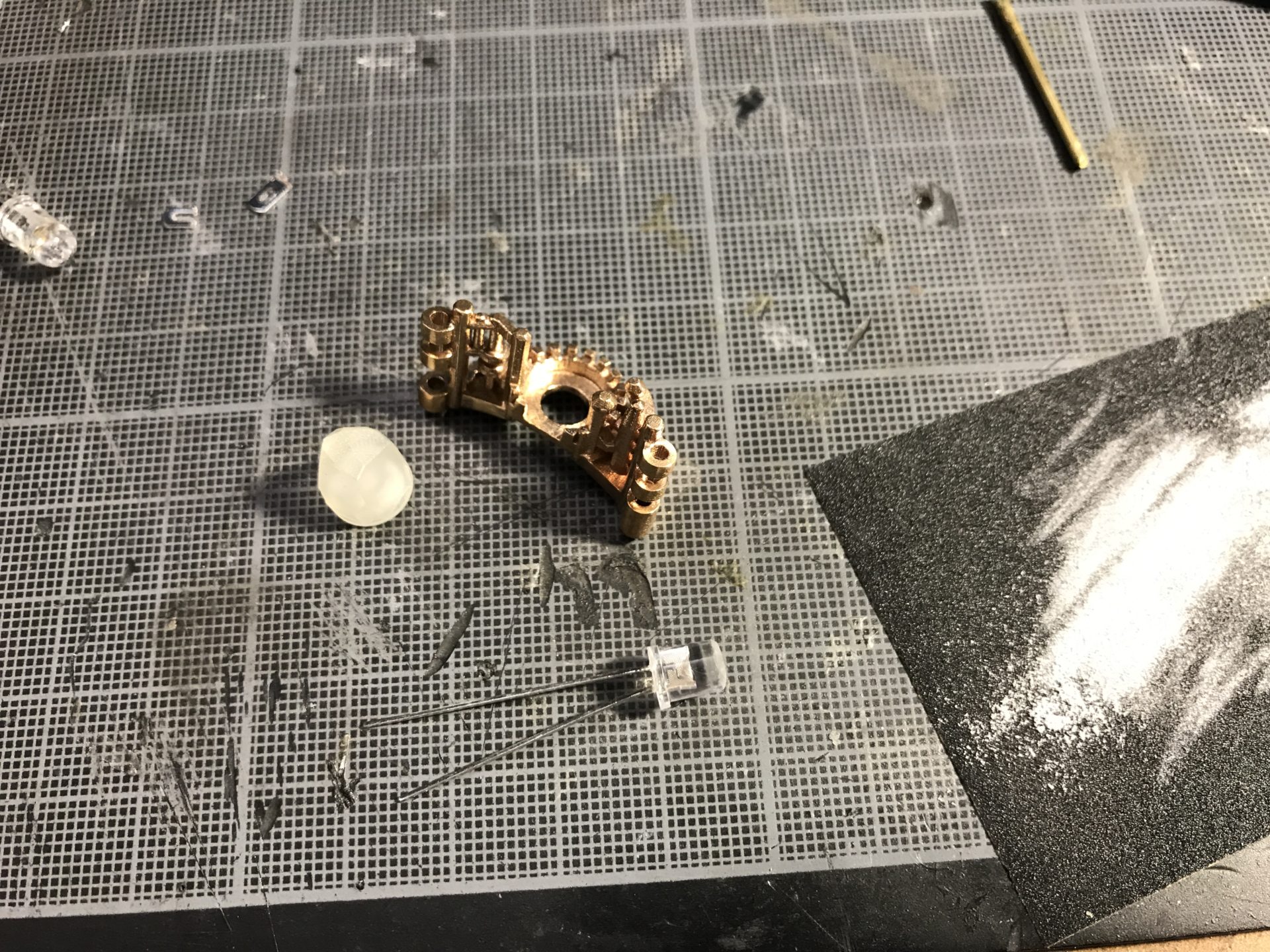
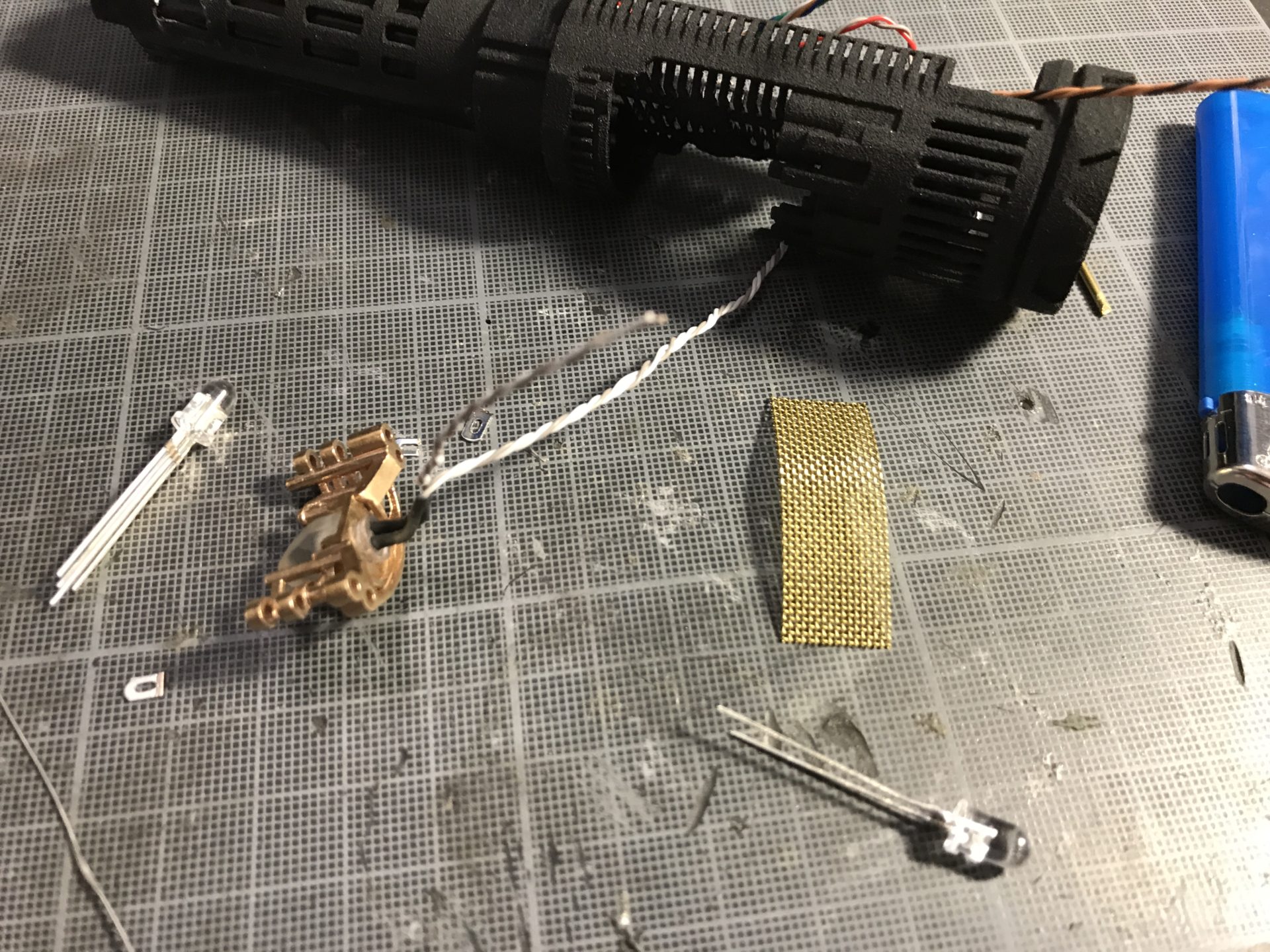
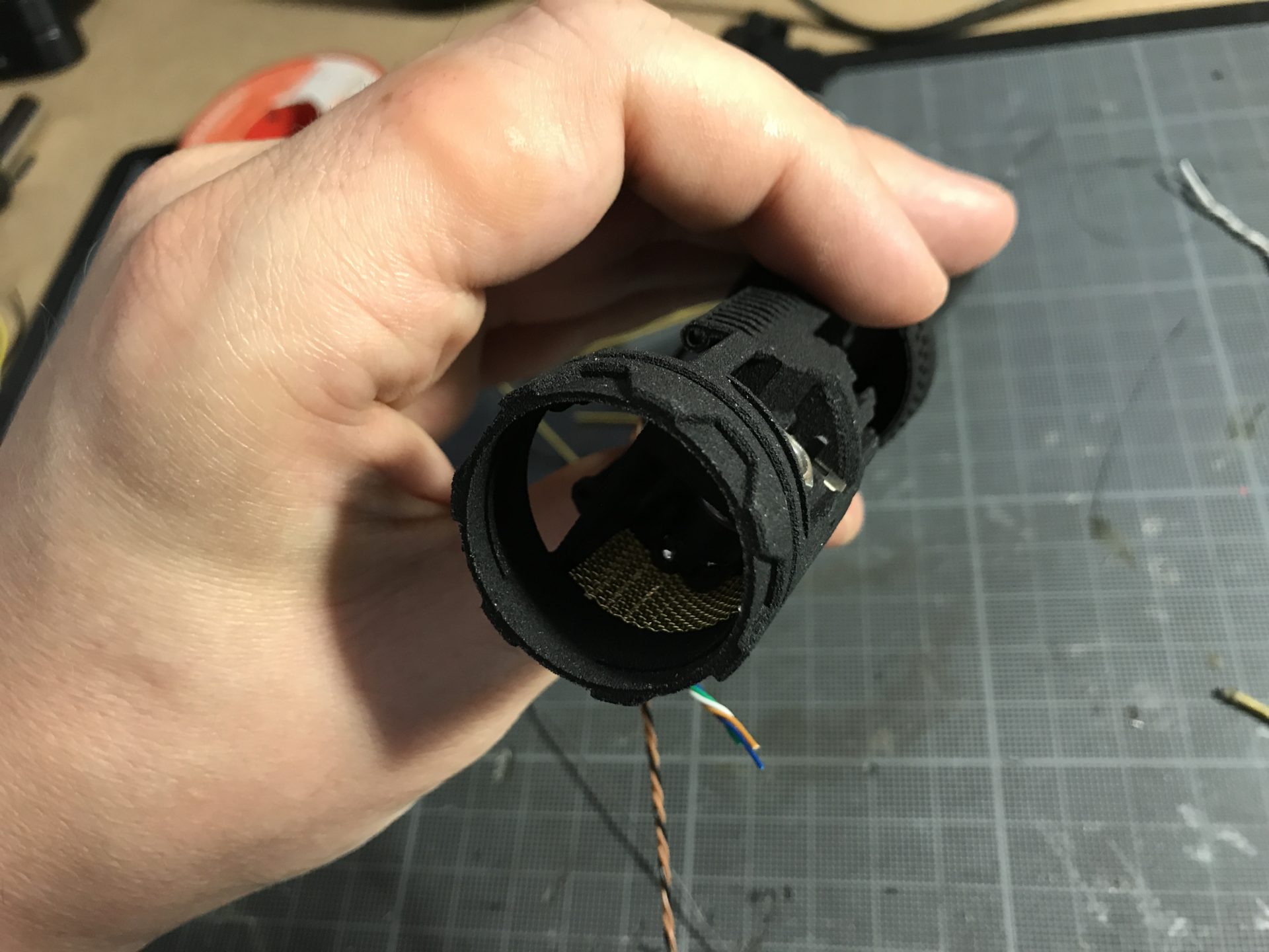
Notes: you can add additional led on the back as well as metal mesh.
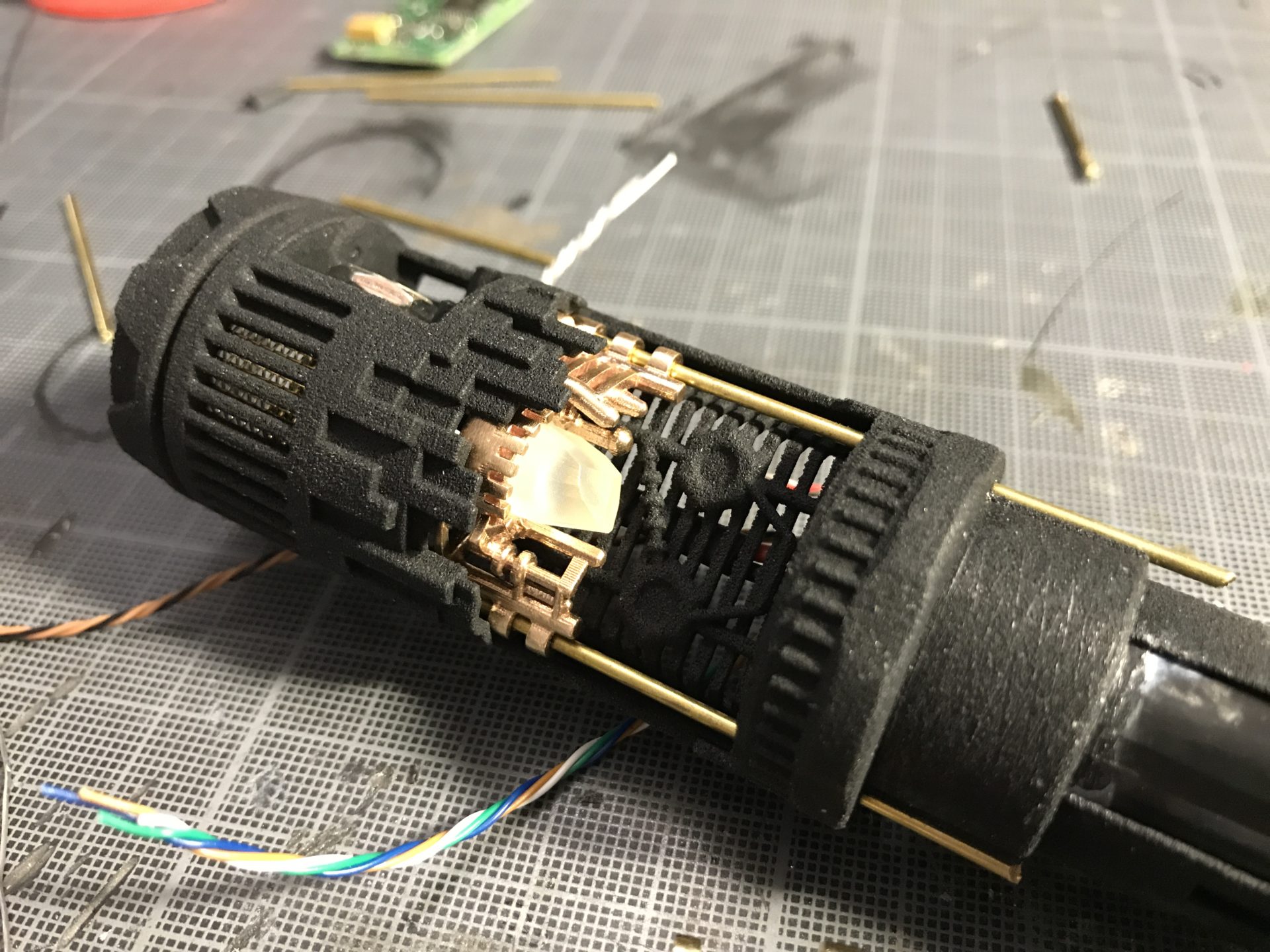
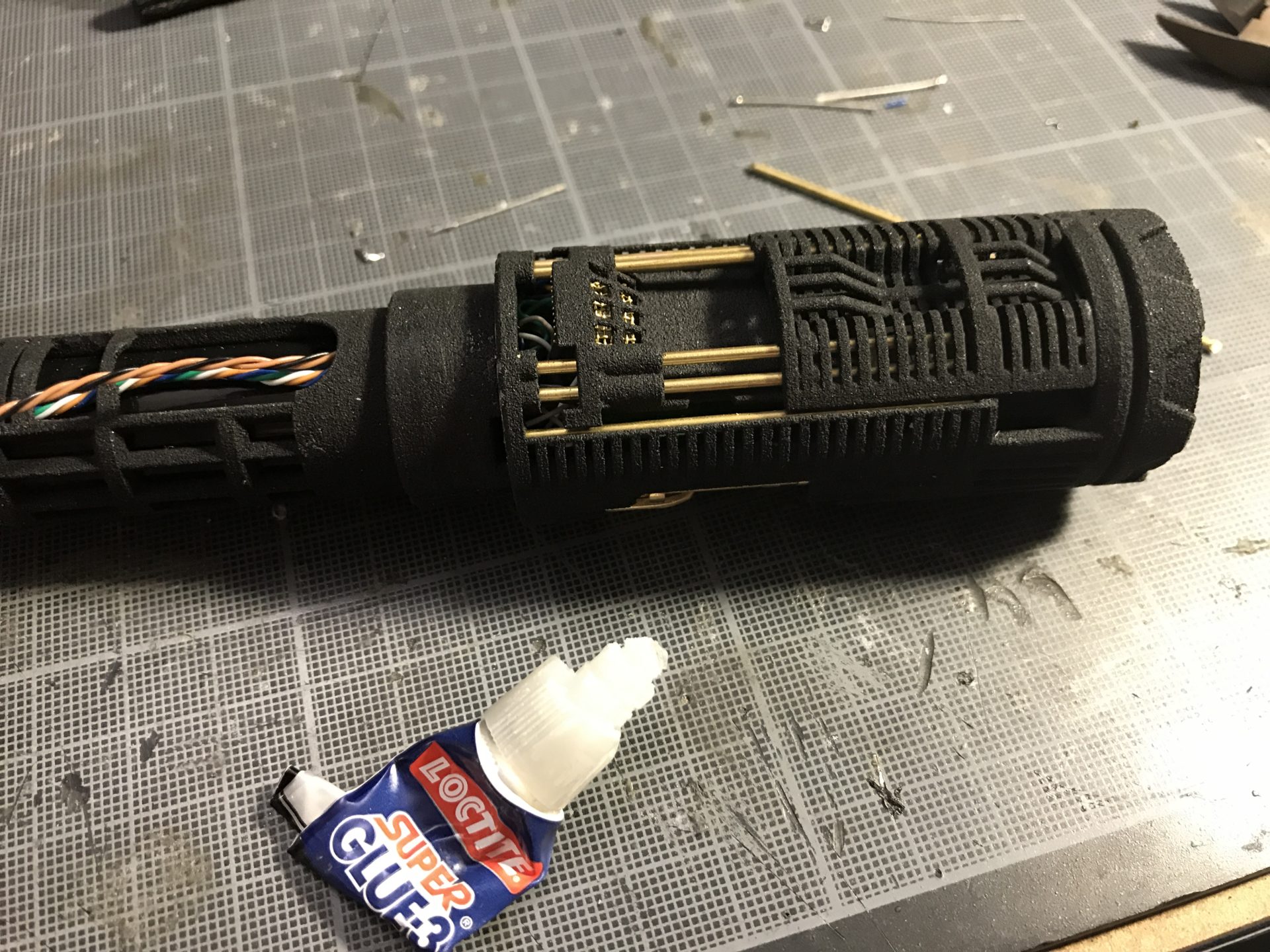
Step 8: It is required to glue the CC insert into place to secure it (tiny bits of super glue will do fine). To properly guide the CC insert into place while gluing it, use long 1.5mm rods (be careful not to glue the rods tho).
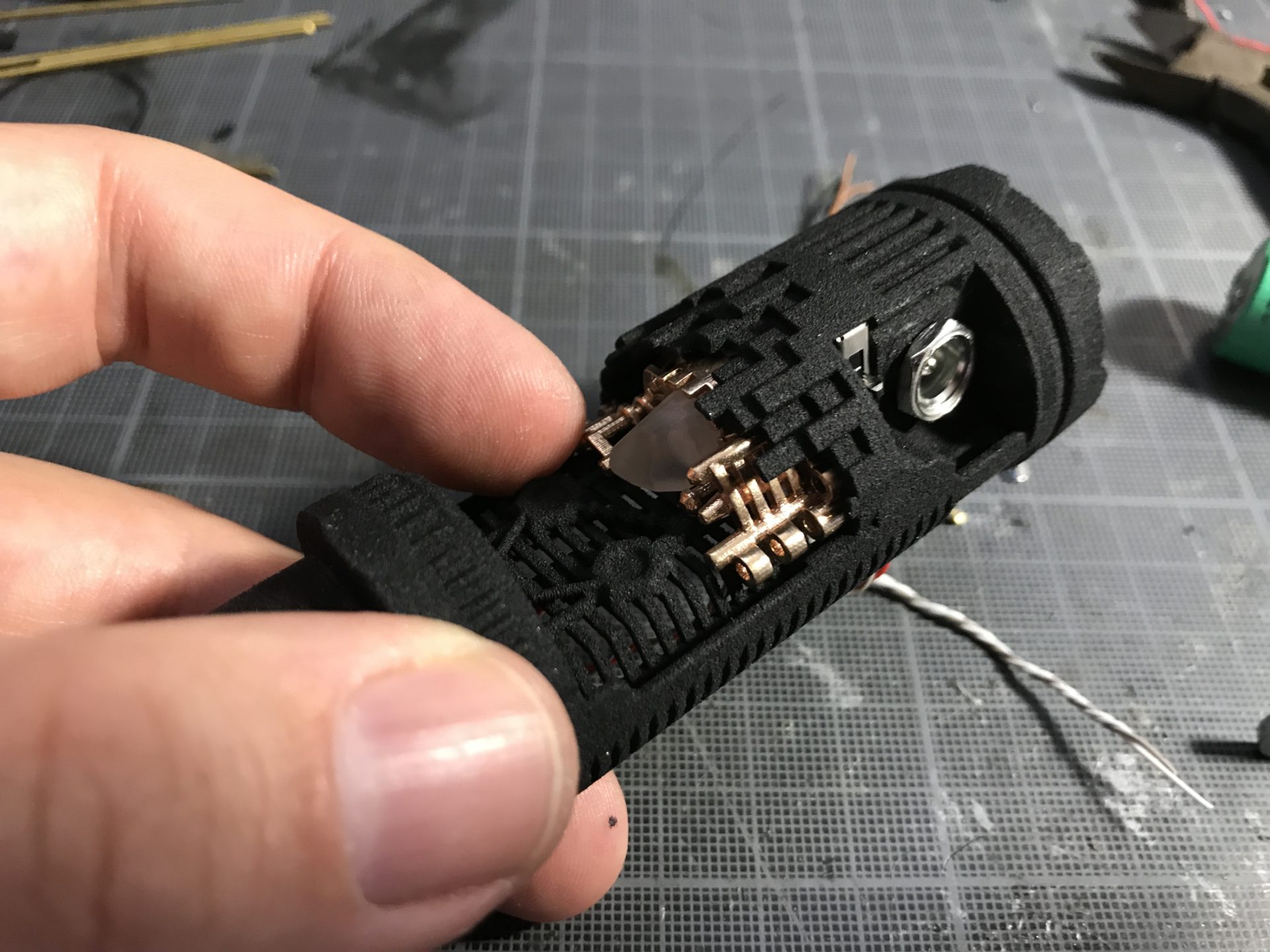
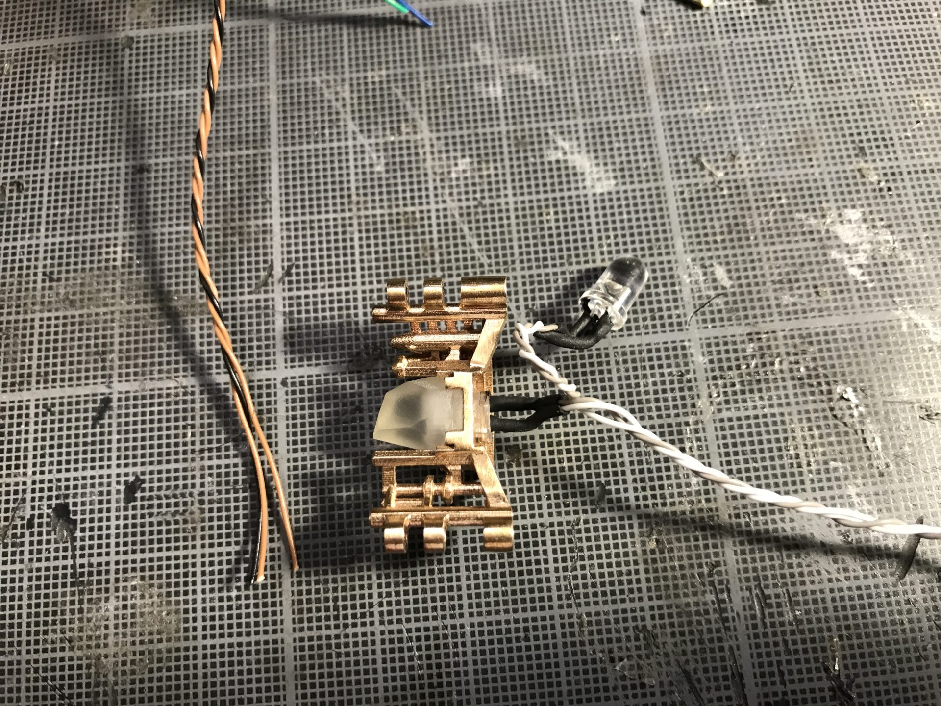
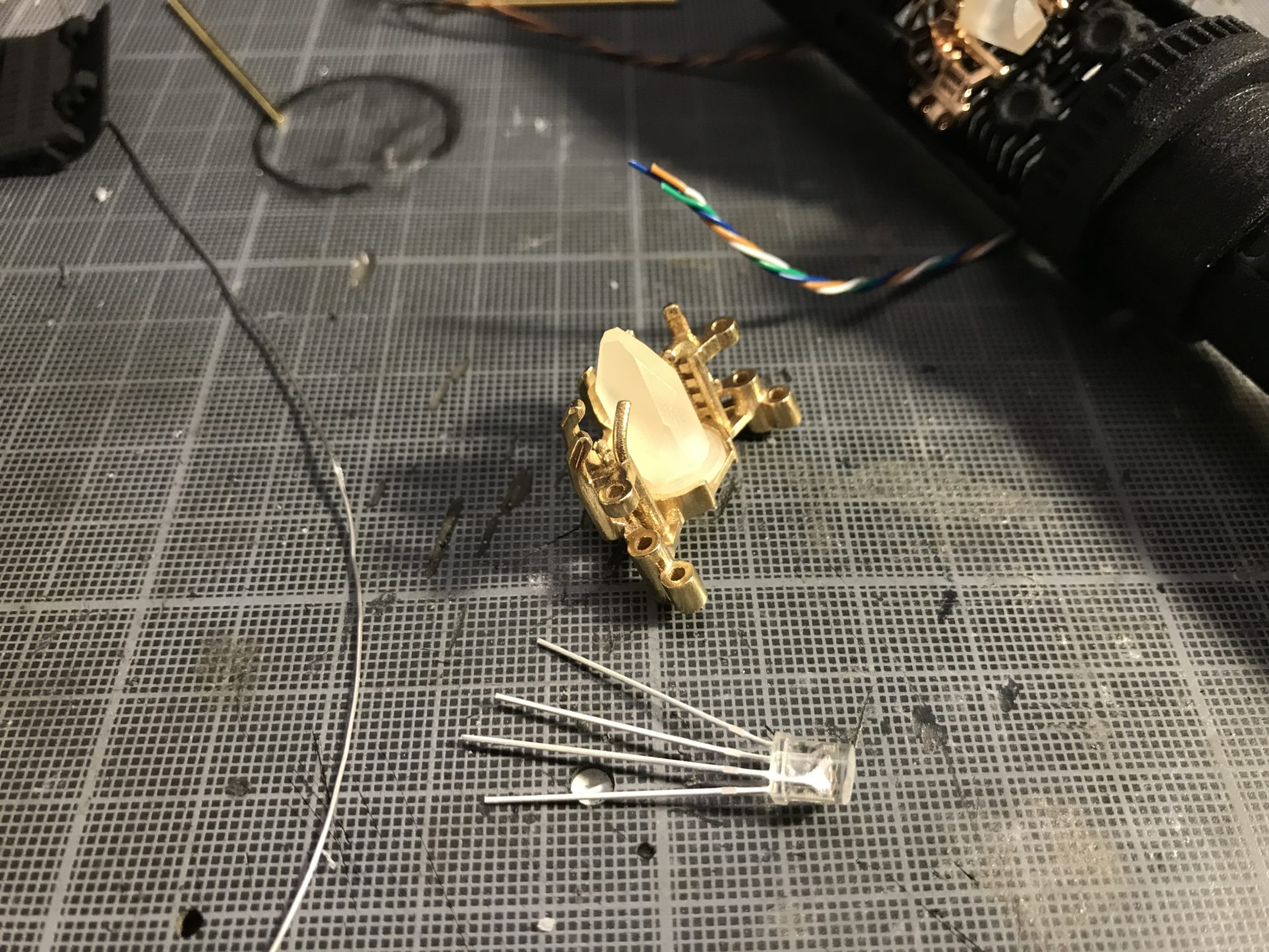
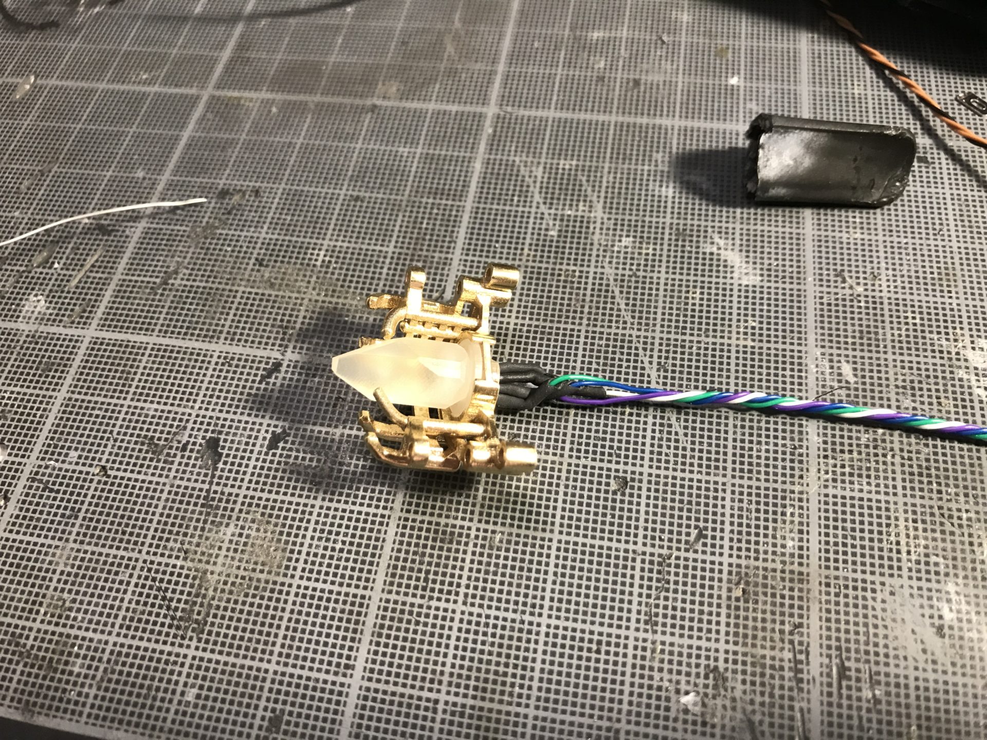
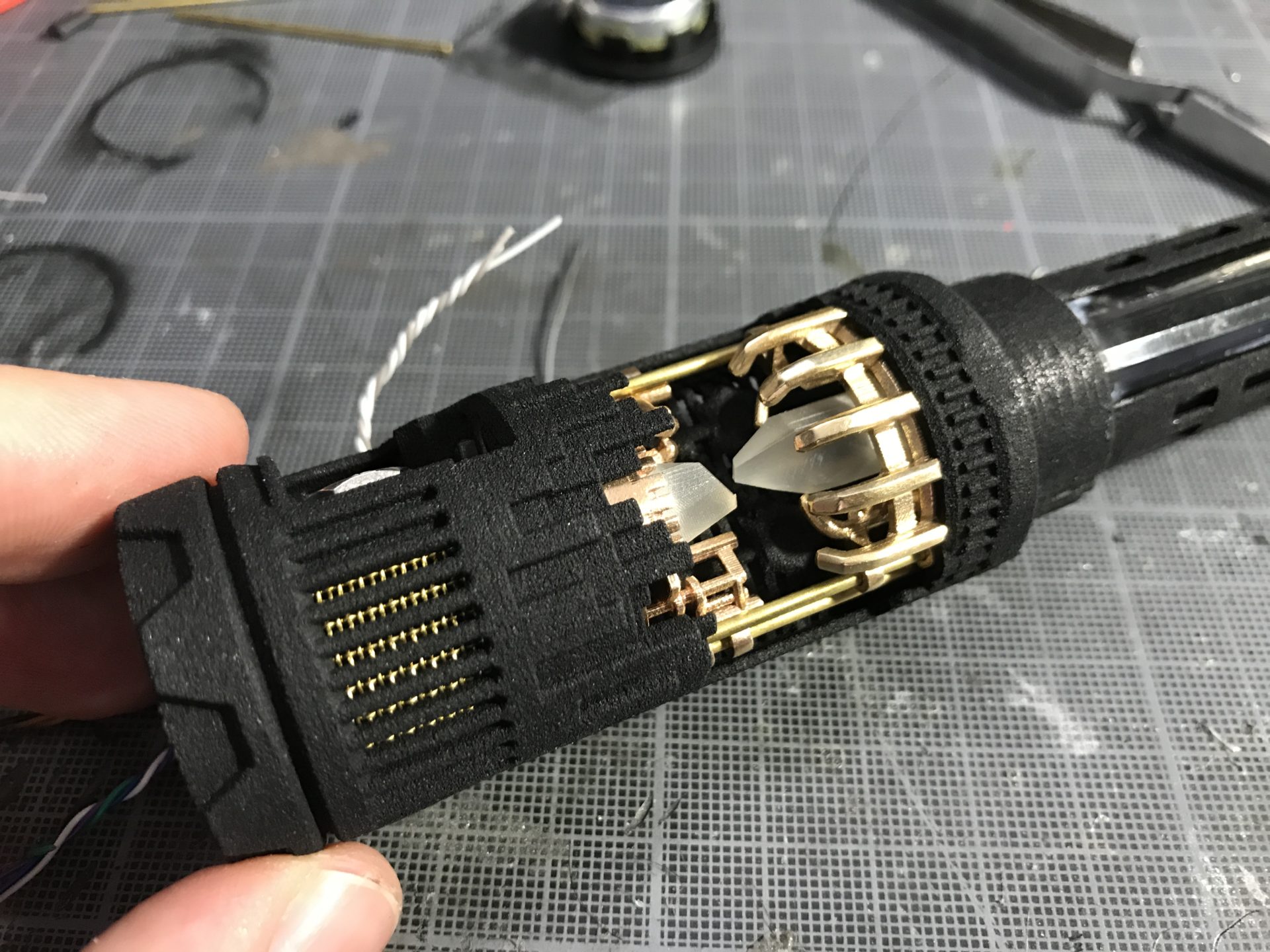
Step 9: Prepare CC insert one (here we use a 5mm common anode RGB accent led FYI). Smae remark as before, if you use the 3D printed crystal, use the long one and send a bit your accent led for it to fit flush.
Step 10: Install the CC Insert one, again gluing it is required, and you can use the rods as guide. Once installed properly, you can install the 4 support rods as well.
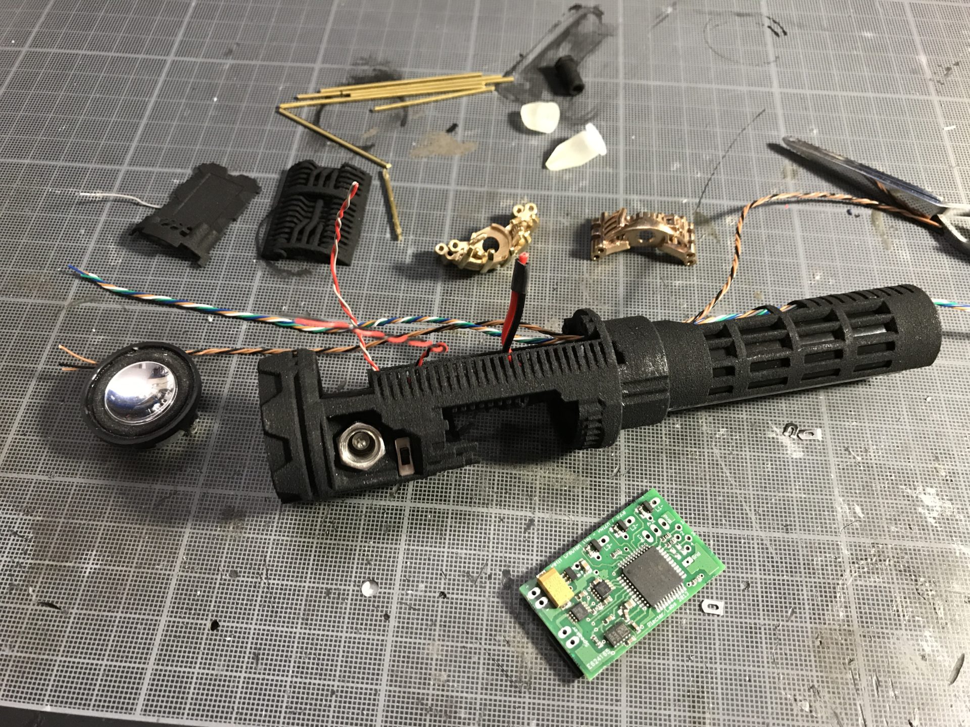
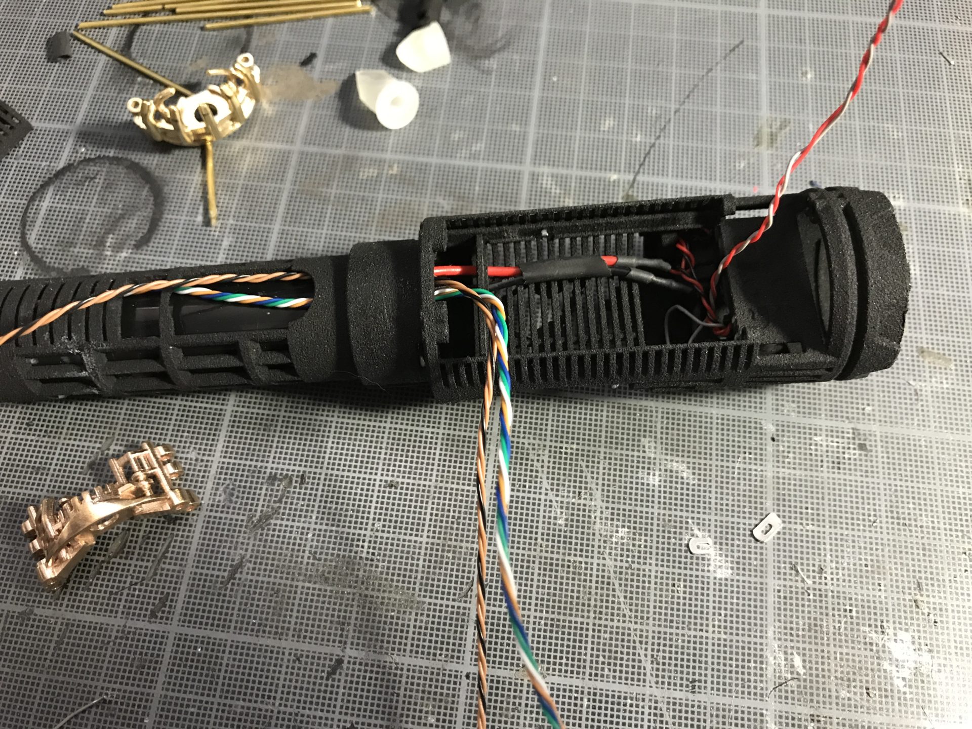
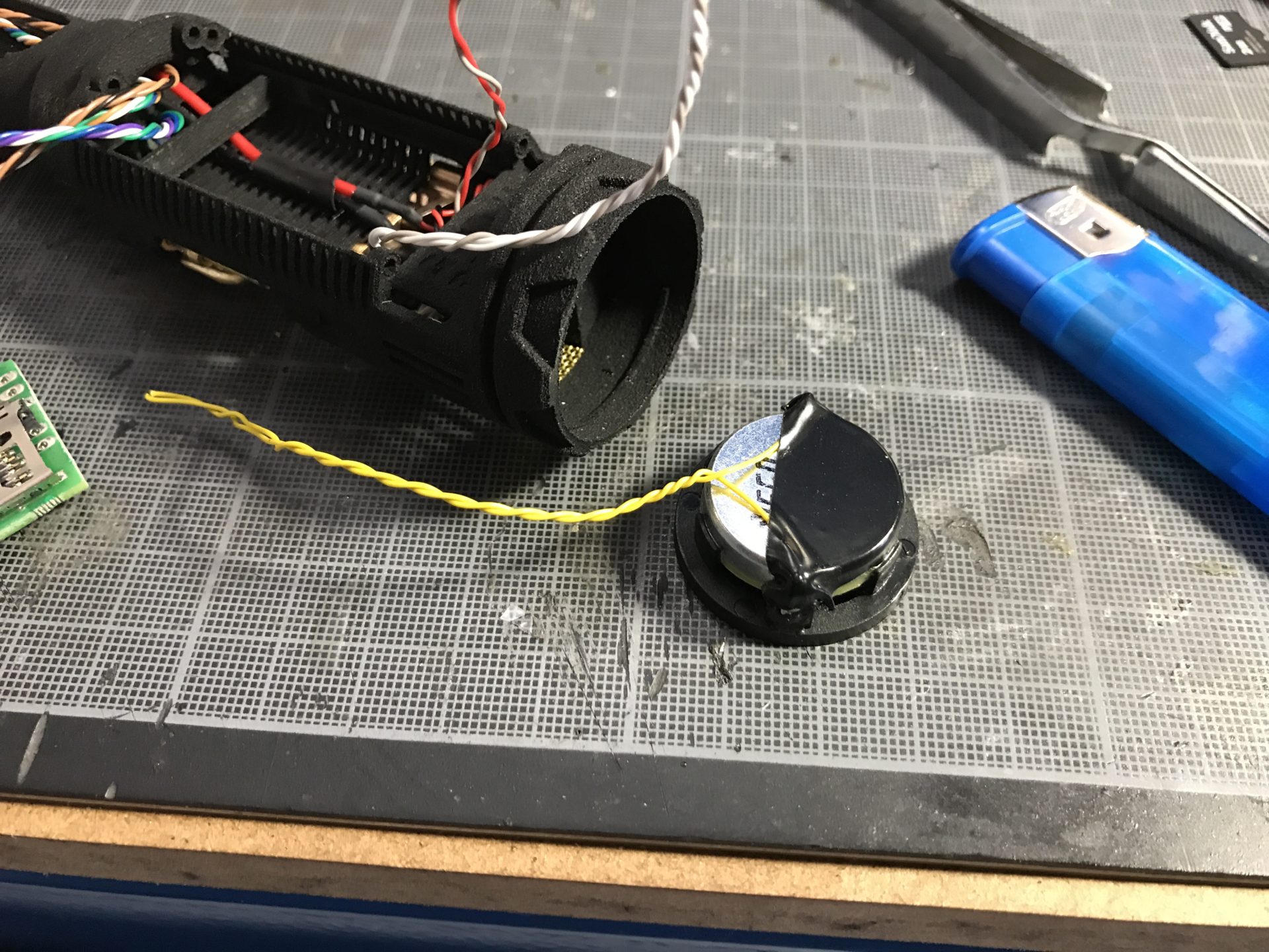
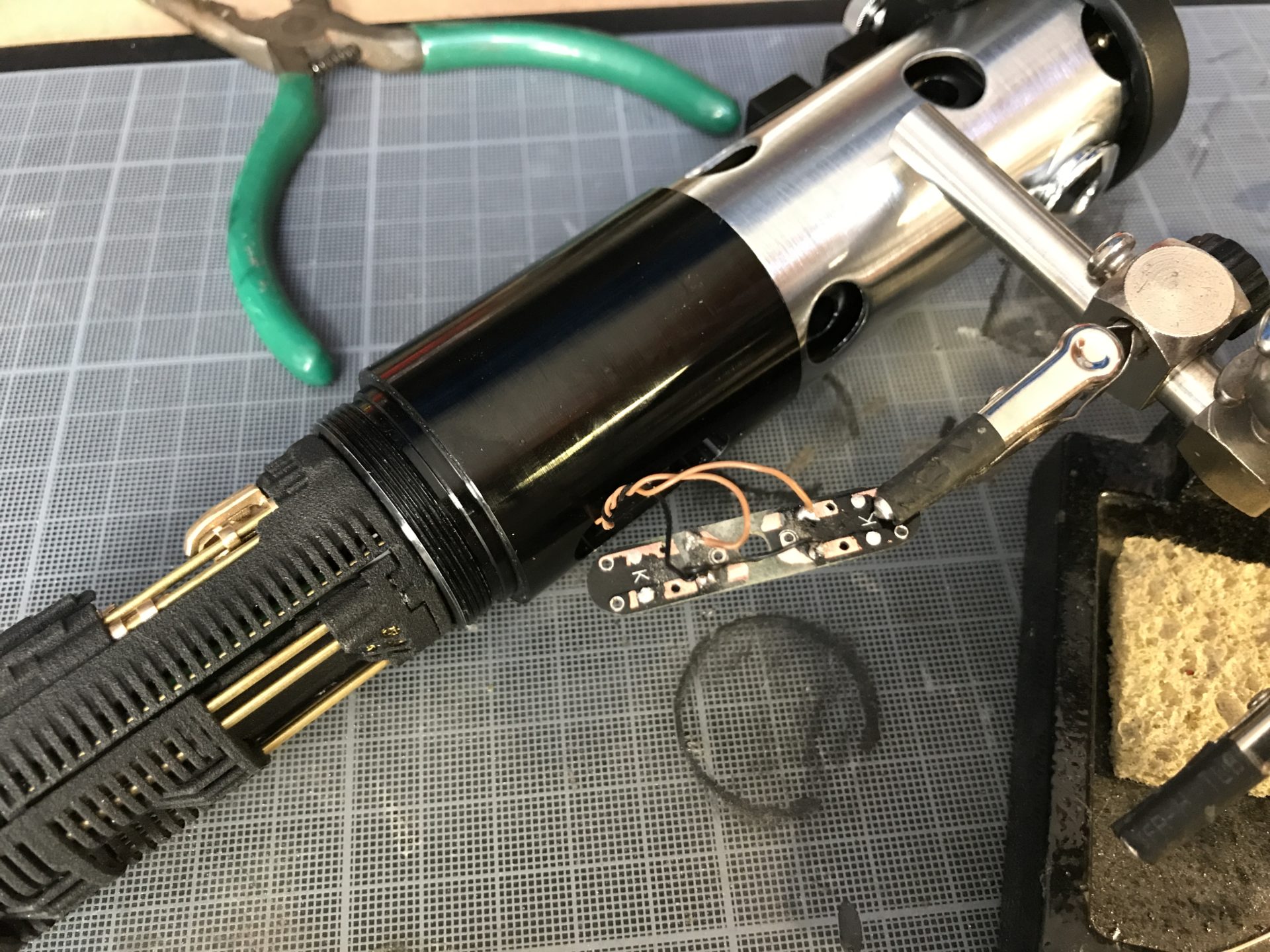
Step 11: Wire and install the 28mm speaker. Use tiny bits of super glue to secure it into place.
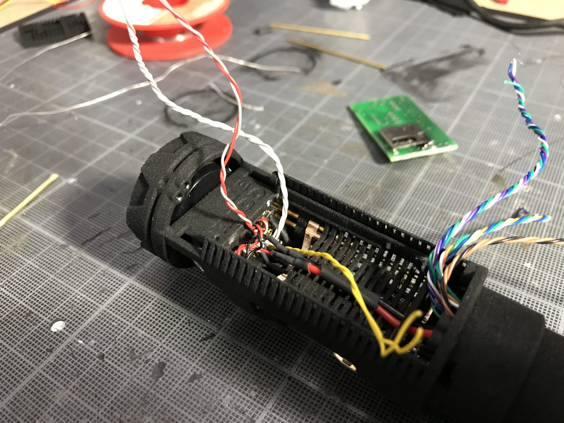
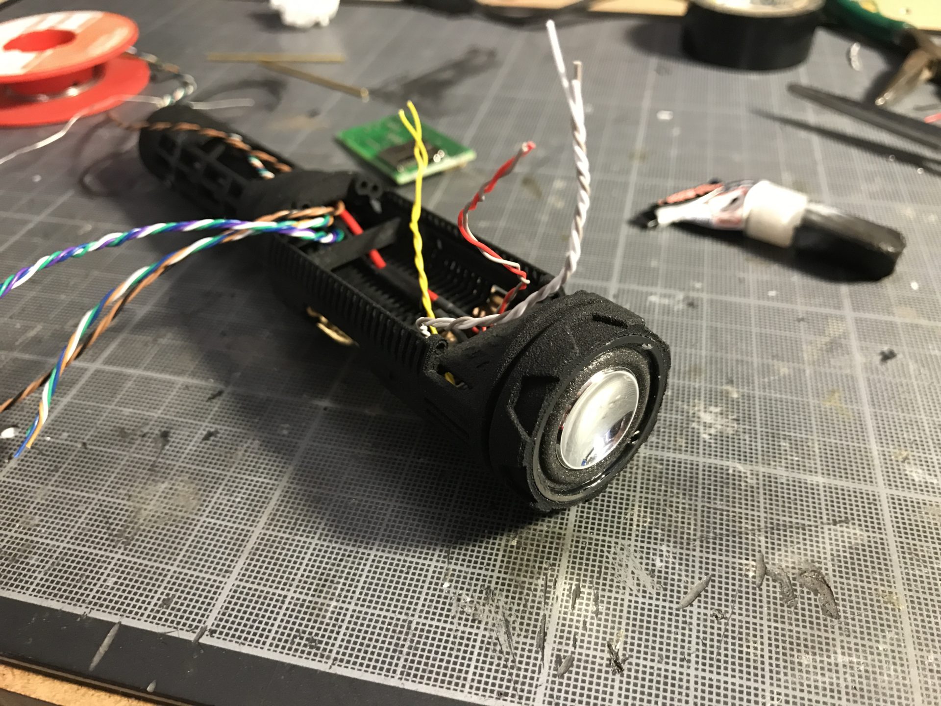
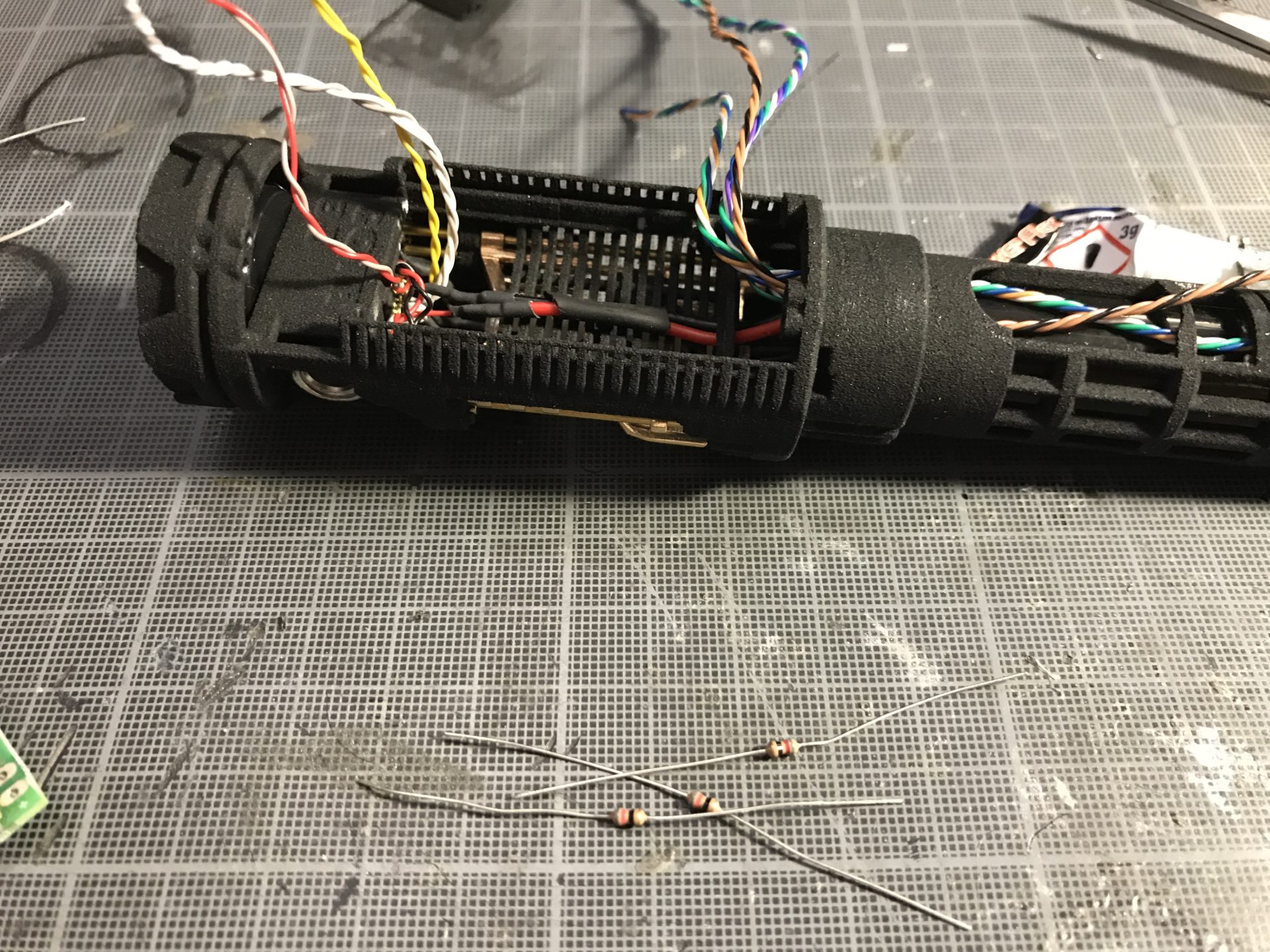
Step 12: Add all the required resistors, there are enough space to hide them over the CC inserts.
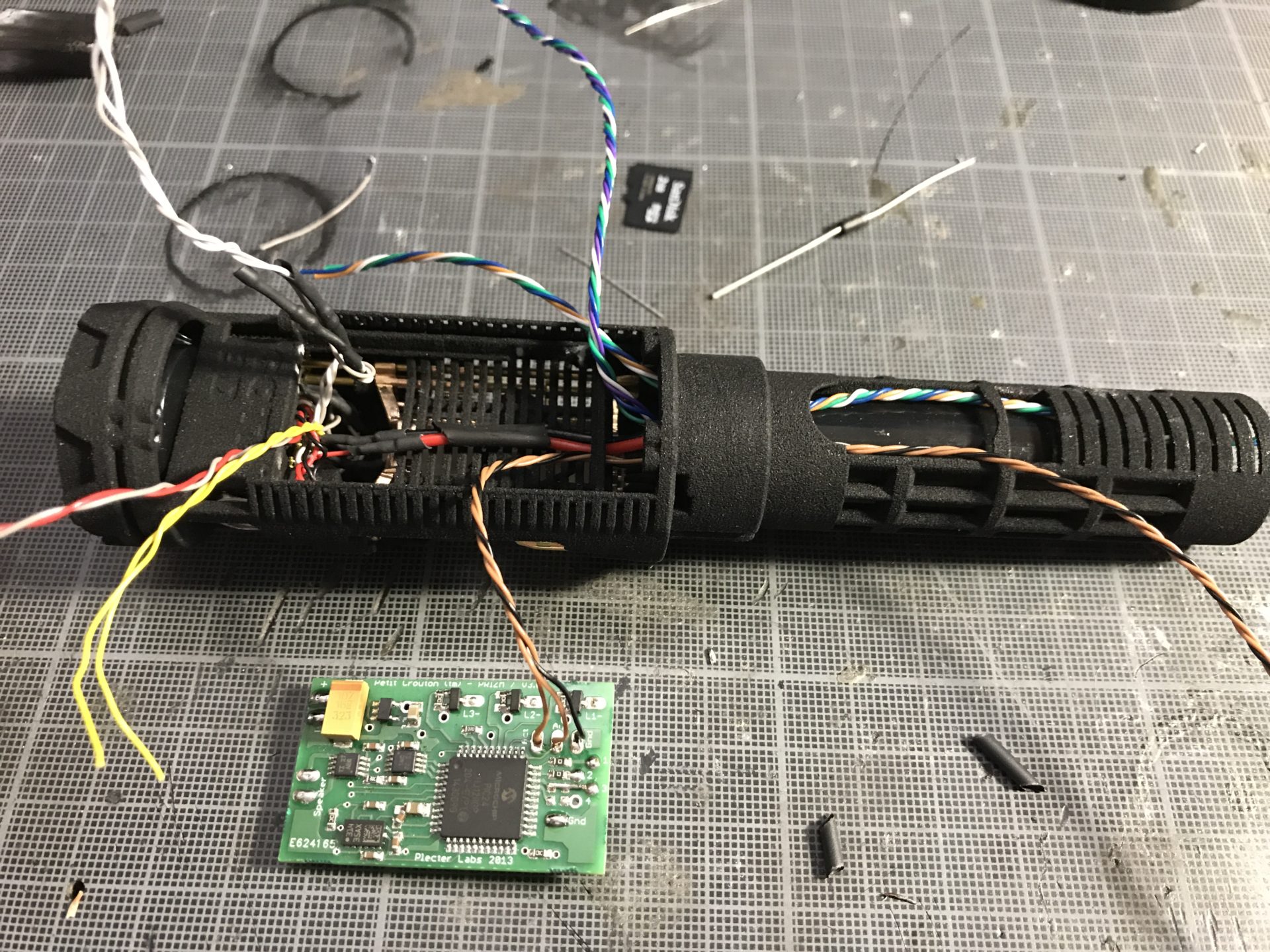
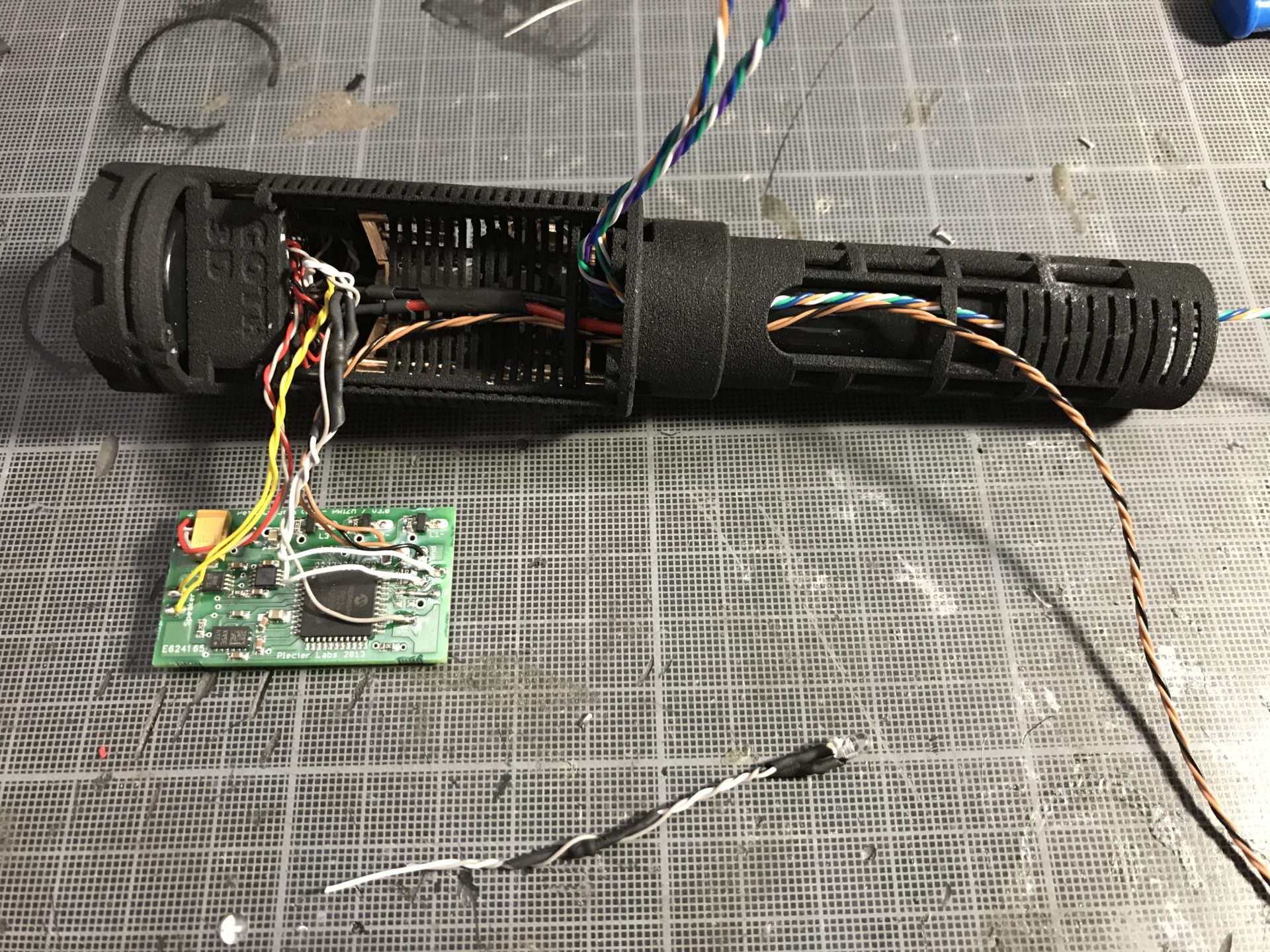
Step 13: Install the soundboard.
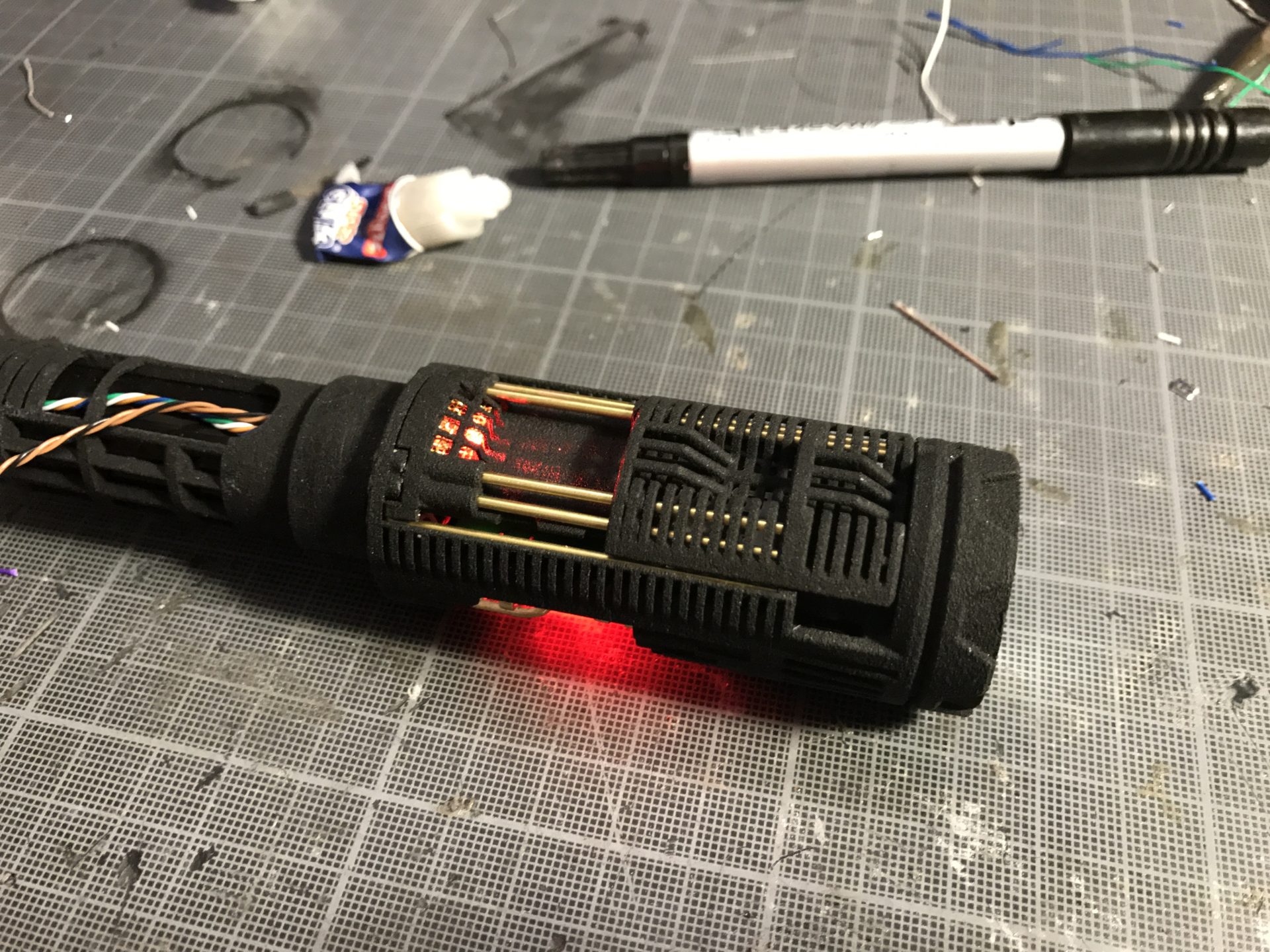
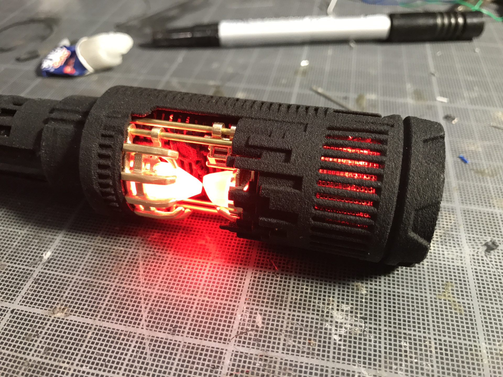
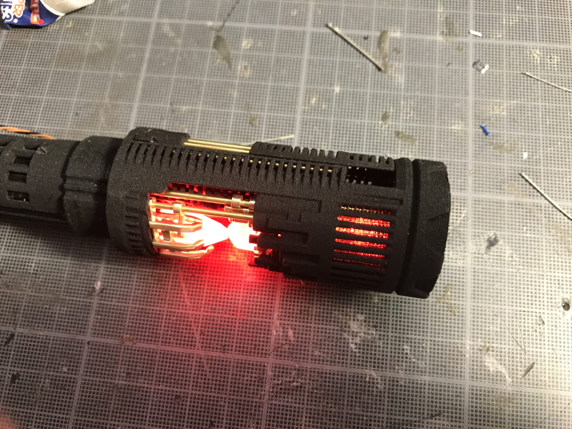
Step 14: Wire and install the main led.
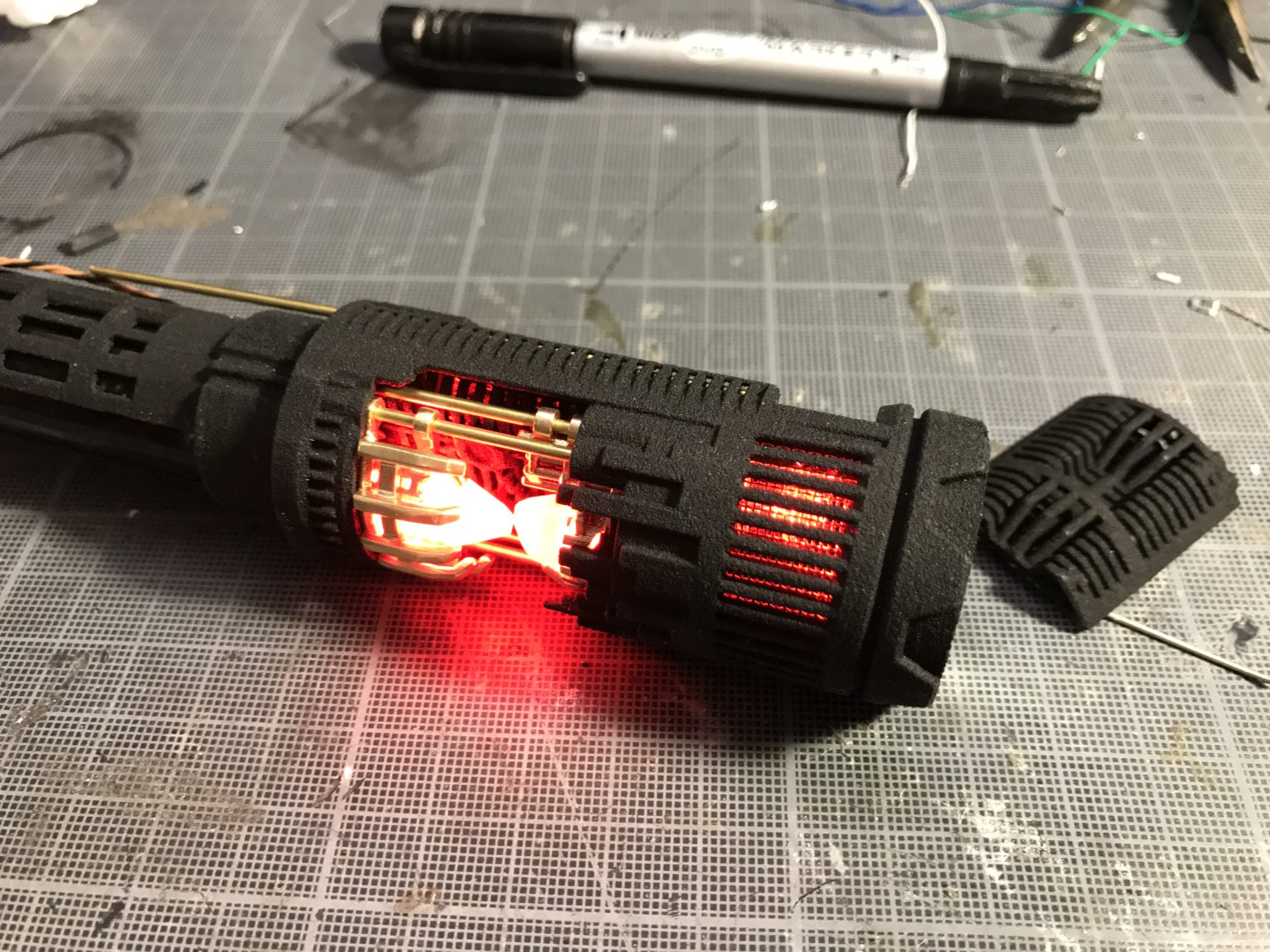
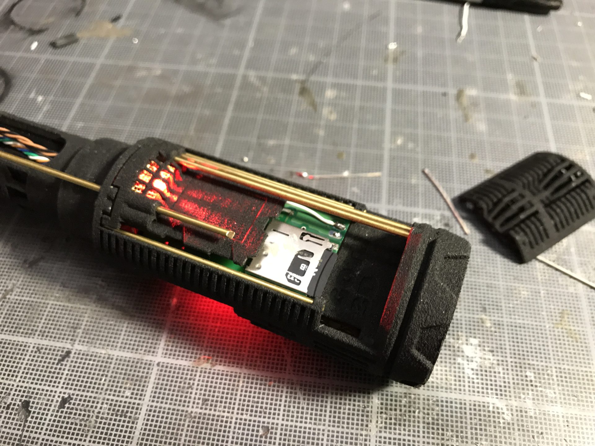
Step 15: Make sure to test everything is working ok.
Step 16: Install the soundboard covers. They use four 1.5mm OD rods, two of them cover the full length, and the 2 others stop at the SD card level (see pictures below). Start by installing the flat cover, then the rounded one, and then secure them with the 2 longs rods.
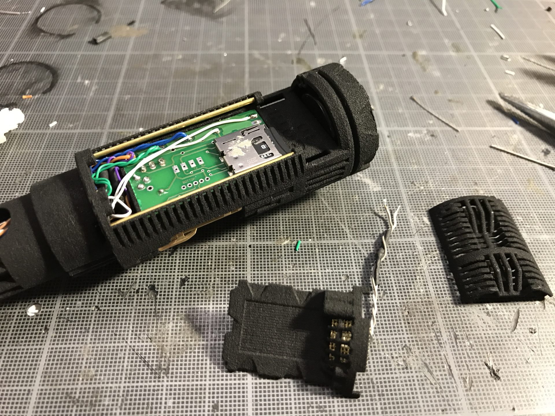
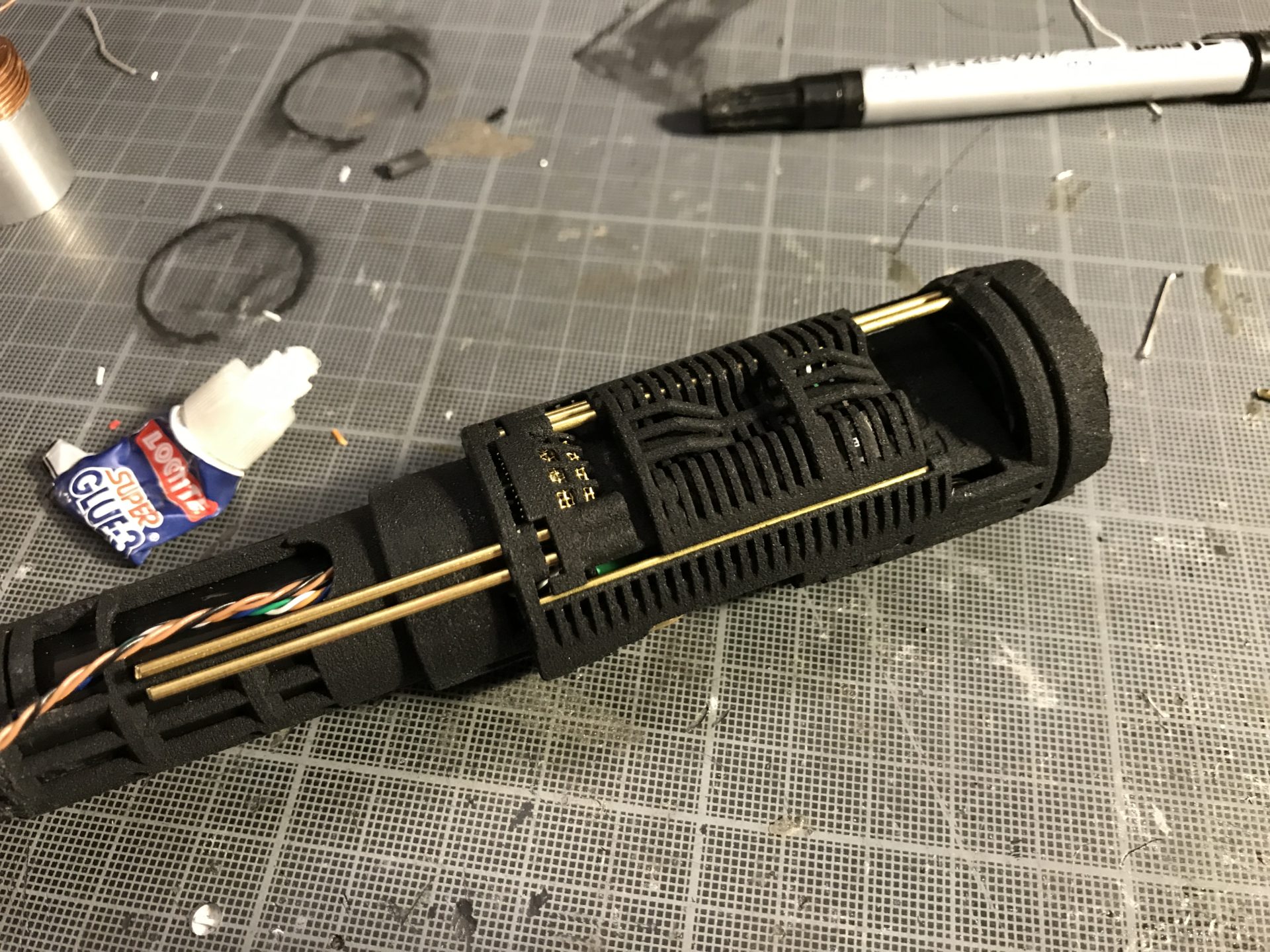
Add the 2 short rods, and test that the rounded cover slide back and forth properly. Once tested fine, glue the rods with a bit of super glue as shown below. Finally, glue the flat cover to the main chassis so that it won’t move (again, only tiny bits of super glue are sufficient).
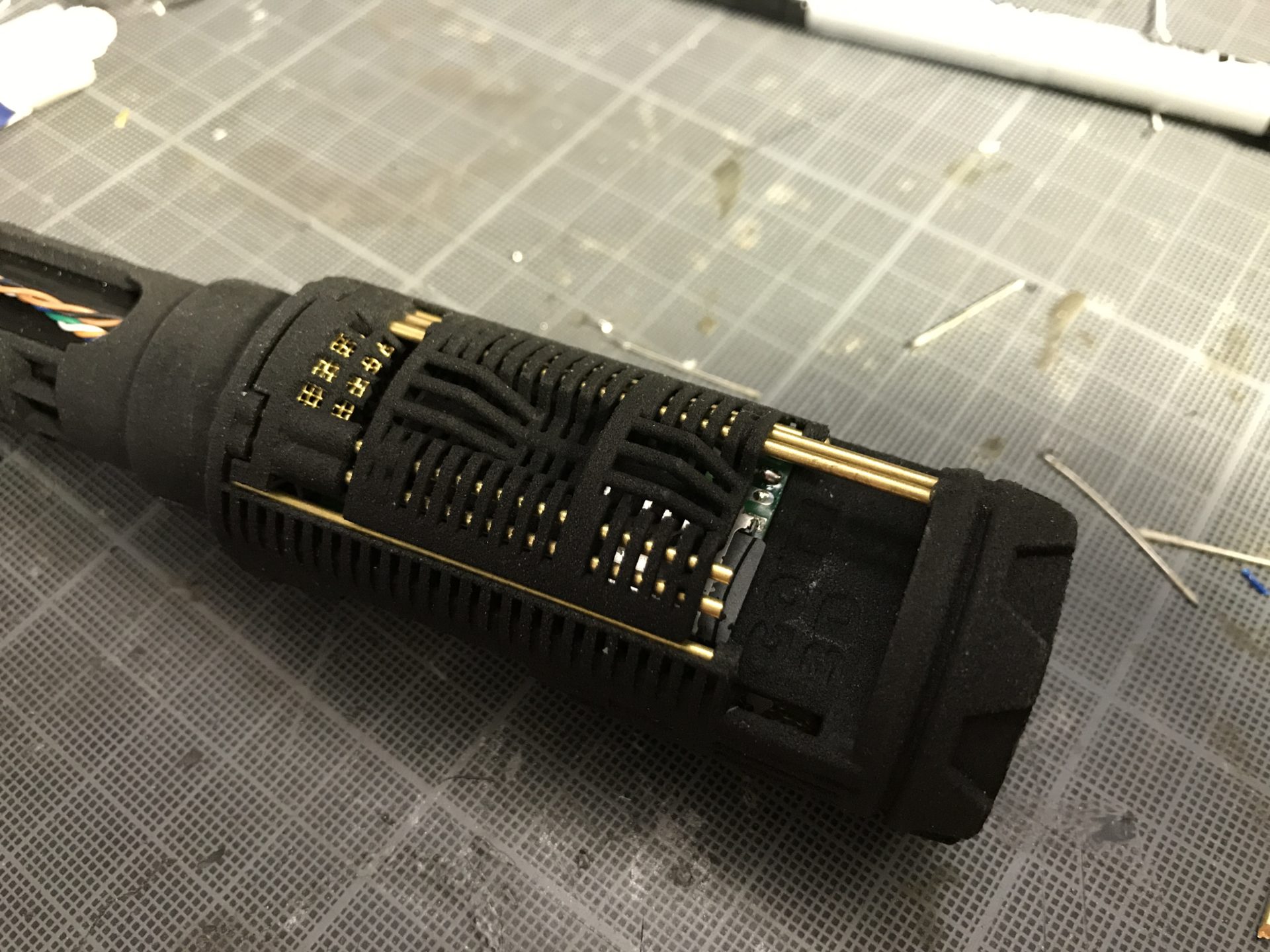
The chassis is now fully ready.
Step 17: Insert the chassis into the hilt upper section. The chassis is press fitting the section, gently force it in place (or sand a bit the upper section ID and add a retention screw to secure the chassis – drill and tap required). Make sure to fold the switches wires properly, so that they can be extracted easily throught the upper section switch holes.
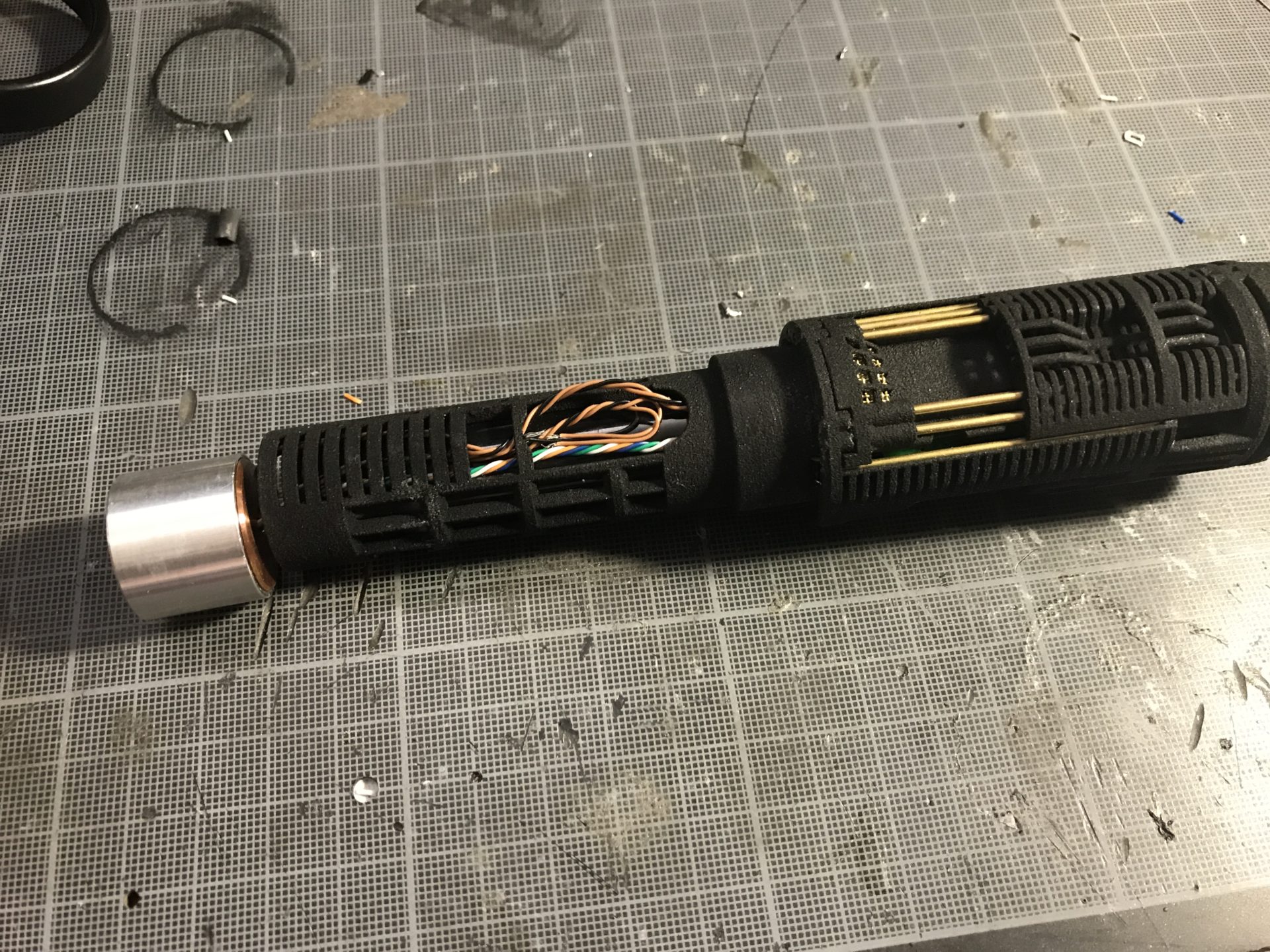
Step 18: Secure the led module using the 6-32 retention screw hole (using a short retention screw).
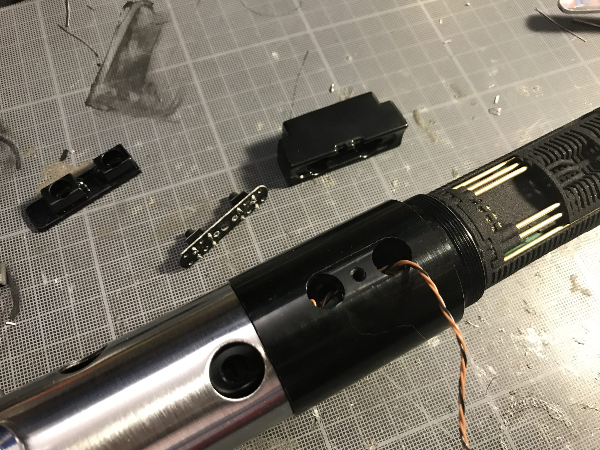
Step 19: Wire the switches and install the control box and switch plungers.

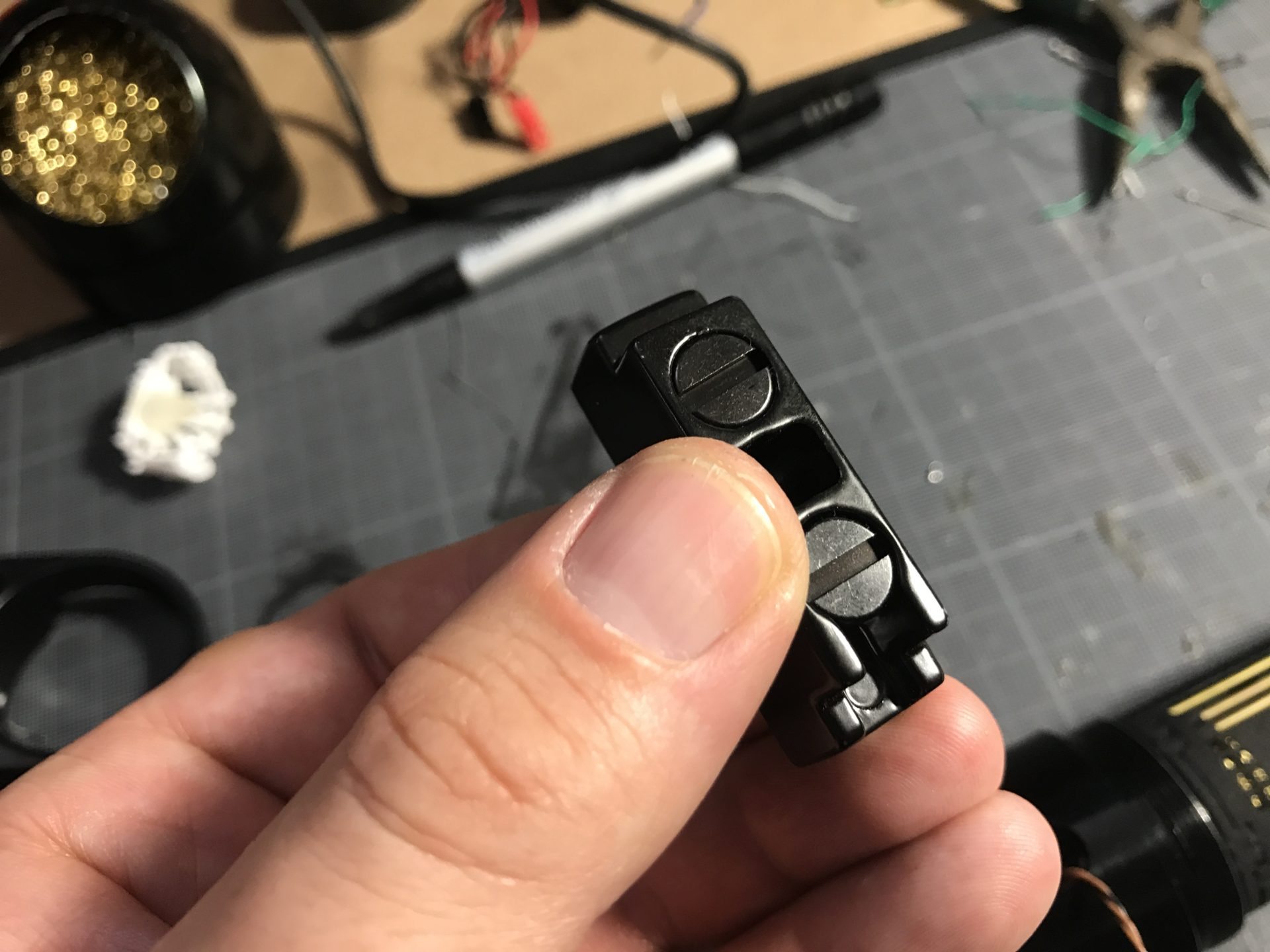
Notes: On the version we received, both switch were acting as one (connected to each others), this is ok for NB use. But since we needed an Aux switch, we sanded the card at the middle to disconnect them.
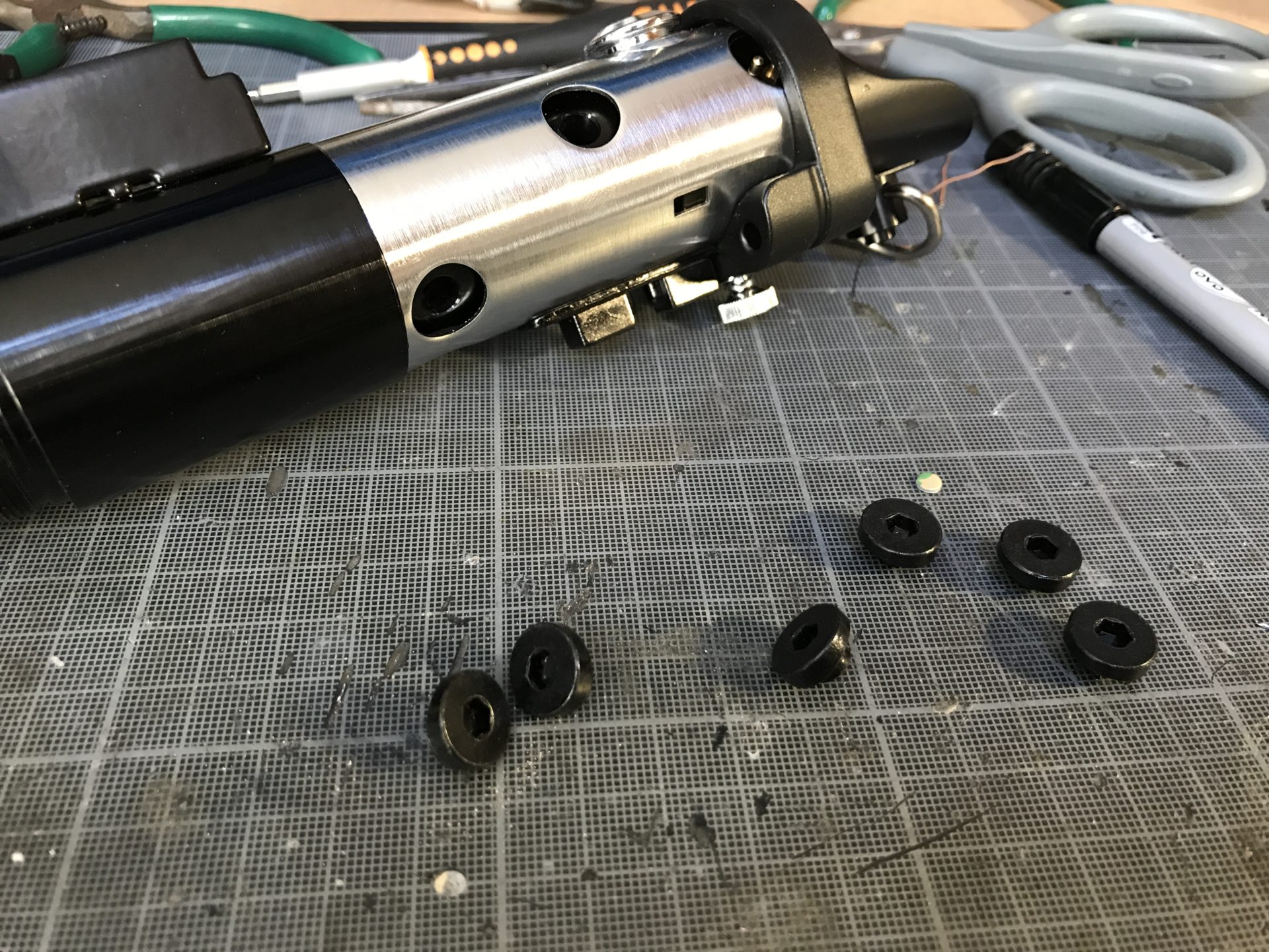
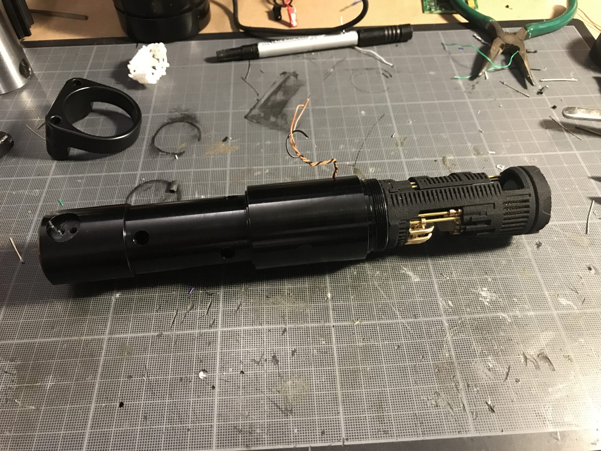
Step 20: Assemble the rest of your hilt. Make sure to test again before adding/gluing the black screws.