Here is a custom hilt design by Solo Sabers! It's a two handed beast sword and we made a nice Master Chassis reveal for it. Spinning plasma gate, crystal chamber add-on, innovative battery cover… check out all its cool features!
Rods and Tubes:
– 1mm OD rod (to be bent and adjusted manually)
– 1.5mm OD rods (1 x 48.25mm, 1 x 41.25mm)
– 1mm OD Rod or Tubes (to be cut manually)
– 3mm OD tubes (3 x 39.75mm)
Magnets:
– Magnets 2mm x 2mm x 16
– Magnets 2mm x 1mm x 16
Introduction
-
Disclaimer
GOTH-3Designs cannot be held responsible for any mistakes made by DIYers during their install. You must have a good understanding of what you’re doing, of the components used and the safety measures associated to them. Always wear protective gear when working on install (gloves, eye protection, …), GOTH-3Designs cannot be held responsible in case of accident.
-
Note #1
Always use the smallest wires to make your install easier. There can be big differences between one wire type and another for the same AWG specs. PTFE Wires with the smallest OD are recommended such as those sold at The Saber Armory. A good wire management is also required, routing wires properly helps a lot saving space.
-
Note #2
These instructions will not cover how to wire the soundboard, make sure to learn how to by reading the manual. We have also typical soundboards wiring available in the Padawan Tutorials. Always test your install along the way! Verifying that everything works after important steps is better than having to dismount everything because something wasn’t wired properly.
-
Note #3
3D printed parts can have very slight accuracy variations. In some rare cases, some sanding or hole deburring can be required. Additionally, metal parts can arrive a bit bent, but are normally easy to bend back into shape. Consult the FAQ if you encounter issues with parts that cannot be solved easily.
Installation Guide
-
Step 1 – Prepare the chassis parts.
The Plama Gate inserts have to be cut:
Weathering can be done at this stage

Chassis adjustments:
– A mod is required on this part – cut the part as shown to shorten the excess going into the battery slot unsing a dremel cut wheel, then polish the cut with a Dremel brush:

– Another small adjustment is required on the cover, to allow better tolerance for the battery to fit under its cover. Sand the area shown below in blue with a Dremel sand drum, then polish the area with a Dremel brush.


Step 2 – Cut the rods and tubes, and test the chassis assembly. Here we can already glue the tubes and rods to the upper part.


Step 3 – Glue the magnets
There are 4 x 2mmx2mm magnets on the sliding plasma gate shield, with their matching 4 magnets on the plasma gate parts.

8 x 2mmx2mm magnets for the soundboard cover.
16 x 2mmx1mm Magnets for the battery cover.


Step 4 – Glue the plasma gate cap on the clear tube

Step 5 – Glue the motor on the rotative part, then add a little piece of 1mmOD rod. This will help matching the rotative part with the plasma tube.


Step 6 – Glue the plasma tube into its slot, then verify the plasma gate assembly works out (insert, without gluing the motor into the upper part, and join the 2 plasma gate halves).


Step 7 – Install the negative battery tab and the kill switch.


Once wired, glue the kill switch in its slot.
Step 9 – Install the positive battery tab (plan the wiring ahead to make the positive bridging easier)


Step 10 – Install the speaker in its slot


Step 11 – Install the side strips on each chassis sides. There are dots to show the pixels placement and align the strips correctly.
Note: due to late supplies, these pictures show an install with 10 pixels strips. However, 11 pixels strips are needed to cover the right length of the lower hilt body window.

Correct look:
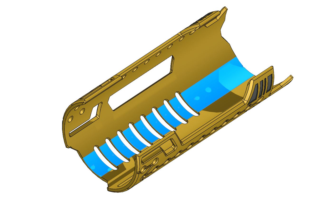
Step 12 – Wire and install the accent pixel strip into the plasma tube. We use a white foam piece for proper light diffusion.


Glue the plasma tube part onto the main chassis.
Step 13 – Manage the wires through the tubes.


Step 14 – Install the pixel ring that will shine behind the rotative part.


Glue it on its slot.
Step 15 – Insert the upper plastic part into the plasma gate top part and secure it with glue.


Step 16 – Insert the motor + rotative part assembly into the upper plasma gate (make sure the motor runs fine and then glue the motor in its slot).


Step 17 – Slide the wires into the tubes and join the plasma gate part together. Make sure to glue each tube and rod properly into the receiving part to ensure the assembly structural integrity.

Step 18 – Install the soundboard


Tidy up the wires once the soundboard install is completed.
Step 19 – Install the accent strip on top of the soundboard


Step 20 – Manage the wires and update the soundboard for testing


Step 21 – A diffusion plastic can be added to the soundboard cover


Step 22 – The battery cover can now be added, sliding it from the side as shown

Step 23 – Insert the chassis into the crystal chamber hilt part, with the previously managed wires going into the right slot for the OLED, accent strip, switches and main NPXL connector)

Step 24 – The inner crystal chamber can now be added and secured using the grub screws.
Note: the following picture is missing the crystal, but the CC must be completed with the crystal before being inserted here.
Note: If the CC add-on is used, it need to be inserted into the CC prior to this step. Make sure it rotate properly and do not press it too much when reassembling the CC side plates / crystal holder (adding some lubrification like WD40 can also help).
Step 25 – The accent strip can be glued (double sided tape) on the hilt using the cover as a guide. Then is can be wired. There are several wiring possibilities according the the soundboard used.. here we have installed the strip in series with the crystal pixel for example, but it could also have been in series with the motor pixel ring.


Add a plastic diffusion piece into the cover and screw it back in place

Step 26 – Install the OLED screen

Step 27 – Install the switches (we used 3mm height brass tactile switches here , which were slightly raised due to the insulation tape under them)


Step 28 – Wire the crystal pixel and glue it in its slot (both a small 5mm pixel PCB or larger 9mm Pixel PCB can be used here.

Step 29 – Assemble back the upper hilt parts and then install the blade connector.


Glue the PCB holder into the hilt emitter.

Step 30 – Optional- some accent 1mmOD tubes can be added to the chassis junction


Install completed, congrats!!