
OLD BUILD INTRUCTIONS
(for chassis purchased before March 2019)
High end and complex chassis assembly for the best crystal chamber and core reveal, with a majority of metal parts.
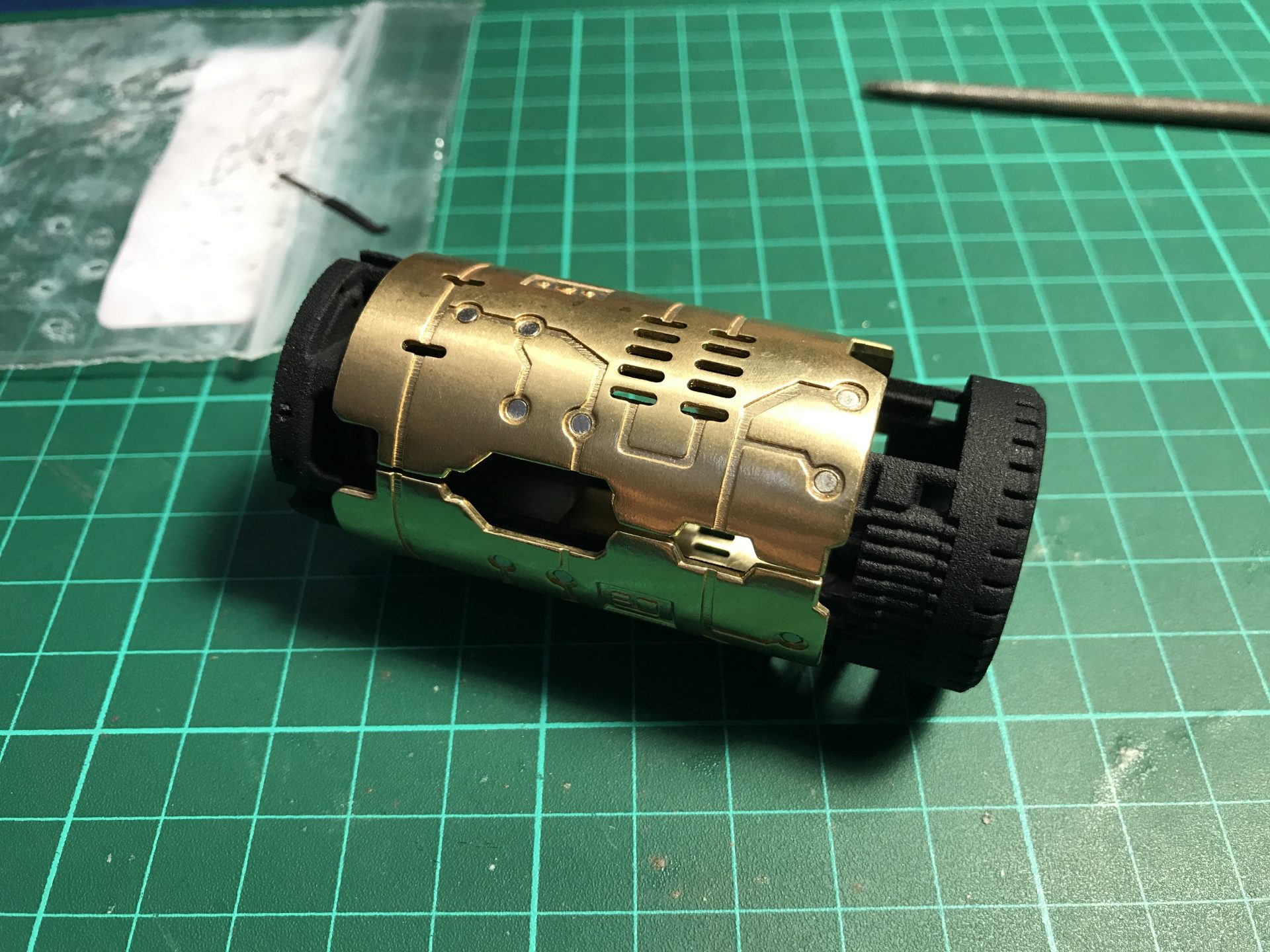
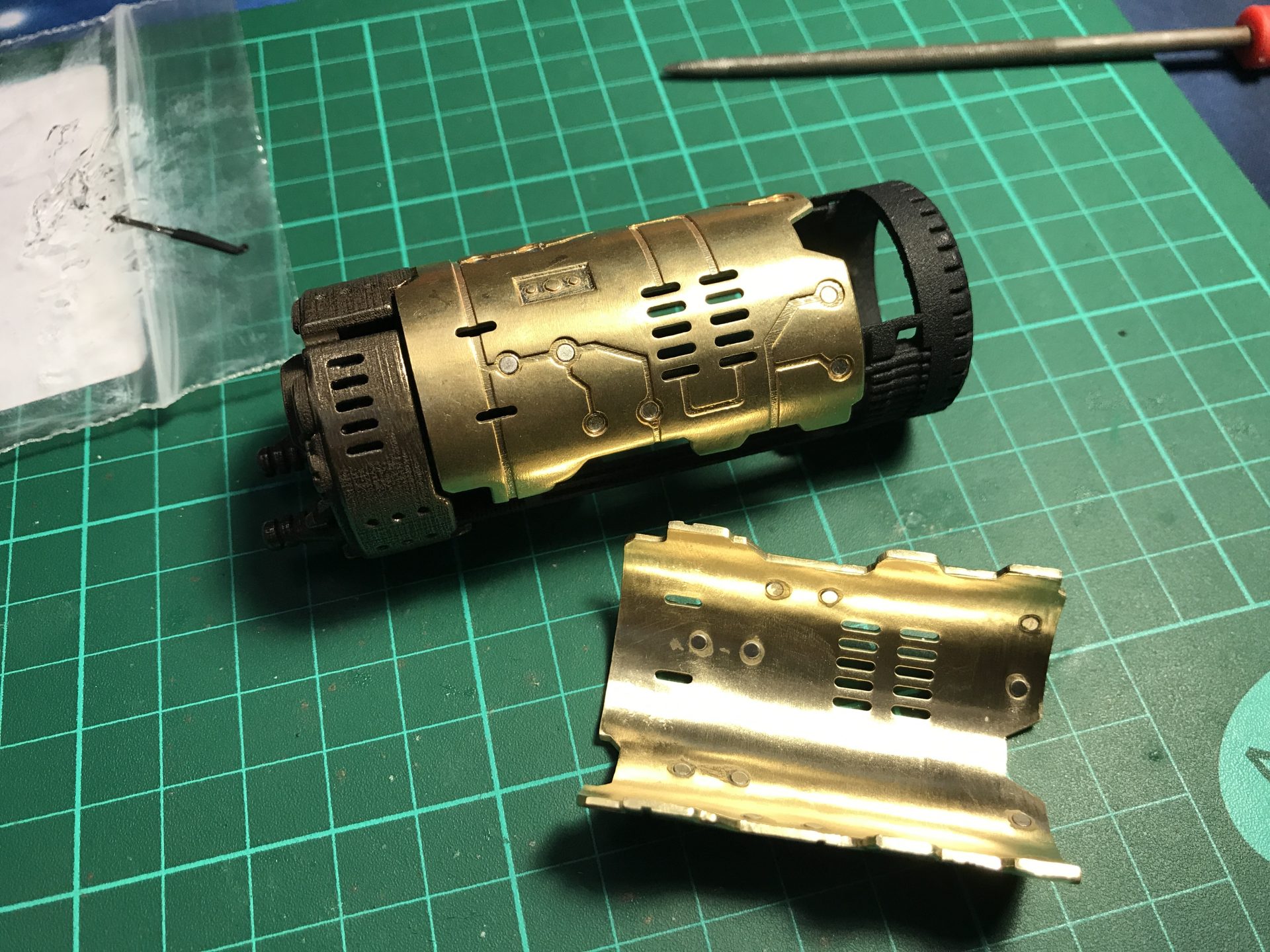
– Reveal-X: Extend your chassis to reveal the focusing crystal, without removing the whole chassis core. The Chassis locks and unlocks using magnets. That’s not all, it uses Magnetik Cover Plates as well, to be removable and reveal what’s “under the hood”
– Rotating Crystal Chamber to power the Primary Kyber crystal – motorized and fully controllable.


Prices: Depends on the materials selected and Shapeways current rate. Build your cart using the links below in order to get a price estimate for the full chassis.
Install Level: Expert
Find below the parts details of our chassis.
All parts can be found in the section C1-2-1 – Graflex Mentor Var1 of our Shapeways shop.
The following parts will depend on the Blade Holder used – NWL Deluxe V2 Blade Holder is recommended for this chassis.
(Recommended materials are mentioned in brackets):
– NWL Deluxe V2:
⇒ Part1 – Style1 (Black Plastic): Energy-Channels-style1
⇒ Part2 – Style1 (Black Plastic or Black Steel): Var2-Switches-Cover-style1
– NWL Master:
⇒ Part1 – Style2 (Black Plastic): Energy-Channels-style2
⇒ Part2 – Style2 (Steel or Brass/Bronze): Var2-Switches-Cover-style2
⇒ Part3 – Style1 (Steel or Brass/Bronze): Blade-Holder-Greeblies-style1
——— or Style2 (Steel or Brass/Bronze): WIP
– NWL Deluxe V1:
⇒ Part1 – Style1 (Black Plastic): Energy-Channels-style1
⇒ Part2 – Style1 (Black Plastic): Switches-Covers-style1
——— or Style2 (Steel or Brass/Bronze): WIP
– KR-Sabers, TGS, Roman (others):
⇒ Part1 – Style1 (Black Plastic): Energy-Channels-style1
The rest of the chassis is common:
⇒ Part 03: Arc-Reactor-1 (Steel or Brass/Bronze)
⇒ Part 04: Arc-Reactor-2 (Smoothest Plastic)
⇒ Part 05: Power-Gate-1 (Steel or Brass/Bronze)
⇒ Part 06: Power-Gate-2 (Steel or Brass/Bronze)
⇒ Part 07: Crystal-Chamber (Brass/Bronze)
⇒ Part 08 – Style1: Cycling-Generator-style1 (Brass/Bronze)
——— or Style2: Cycling-Generator-style2 (Brass/Bronze)
⇒ Part 09: Power-Indicator (Smoothest Plastic)
⇒ Part 10: Power-Cells-Covers (Brass/Bronze)
⇒ Part 11 – Style1: Cover-Plates-style1 (Brass/Bronze)
——— or Style2: Cover-Plates-style2 (Brass/Bronze)
⇒ Part 12: Generator-Gate-1 (Steel or Brass/Bronze)
⇒ Part 13: Generator-Gate-2 (Steel or Brass/Bronze)
⇒ Part 14 – Style1: Main-Generator-style-1 (For CF9 – Black Plastic)
——— or Style2: Main-Generator-style-2 (For I3 – Black Plastic)
⇒ Part 15: Crystals (Smoothest Plastic)
2- Additional chassis parts:
Most of the chassis parts needed for our chassis are available at The Saber Armory.
Local hobby stores or online store (as well as eBay) are a good source for parts.
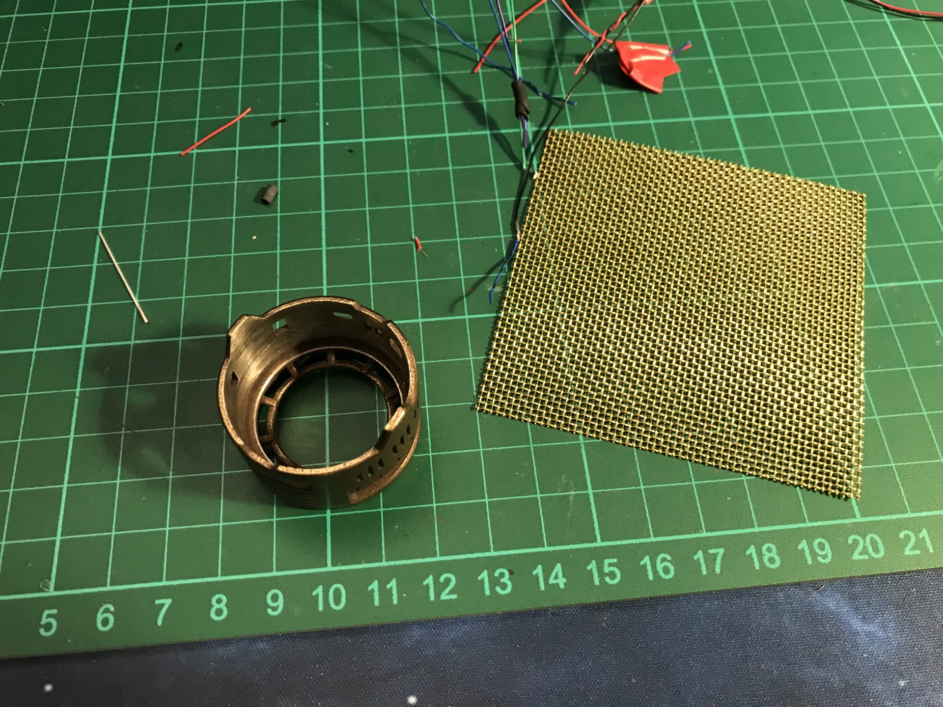
You can also be inventive and add any custom parts, wire mesh, paint job or else to your chassis to give it an unique look!
Here is a list of parts needed to install the Variant1 Chassis
⇒ 4-40 threaded rods x 3 (recommended in brass)
⇒ Brass, Aluminium or Copper tube:
– 4mm OD tubes: 1) 3x 5mm, 2) 1×18,74mm, 3) 3x 30mm, 4) 1x 26,60mm, , 5) 1x 44,50mm, 6) 1x 36mm, 7) 1x 26mm
– 5mm OD Tube: 8) 12,70mm
⇒ Brass, Aluminium or Copper rods:
– 1) and 2) are cosmetic elements on Part01
– 3) 1.5mmOD Rod to be bent in U shape (see build instructions)
– 4) 1mmOD rods are required for support on the rotative CC elements
– 5) 1mmODx53mm and 6) 0.5mmODx7mm are cosmetic elements on Part14
⇒ Optional tubes and rods: You can add an additional mix of rods and tubes to the chassis Part01 and to the Crystal Chamber Part07.
⇒ Neodymiummagnets: 4x 3mmODx2mm and 24x 2mmODx1mm
3- Hilt / GRAFLEX Replica:
Graflex replica sellers:
⇒ Roman’s Props Shop
⇒ Maker Props Studio
⇒ The Graflex Shop
4- Blade Holder:
Here are the blade holders compatible with G3D chassis for Graflex:
⇒ NerfworXlab most accurate blade holder – available at Solo’s Hold
Recommended with the NWL Deluxe Blade Holder
⇒ The Graflex Shop
⇒ The Saber Armory
5- Electronic components and blades:
Saber electronic components are basically more or less similar from one saber to another. You’ll need a main Led, a Battery, a recharge port, one or two switches, a soundboard, accent leds, a speaker and wires. Then the blade is the last part of your saber, they are usually made from PolyCarbonate tubes + tip.
You can find most of what you’ll need at The Saber Armory. Some components can also be found at The Saber Bay on Etsy. Local electronic shops or online stores like Digikey are also a good source.
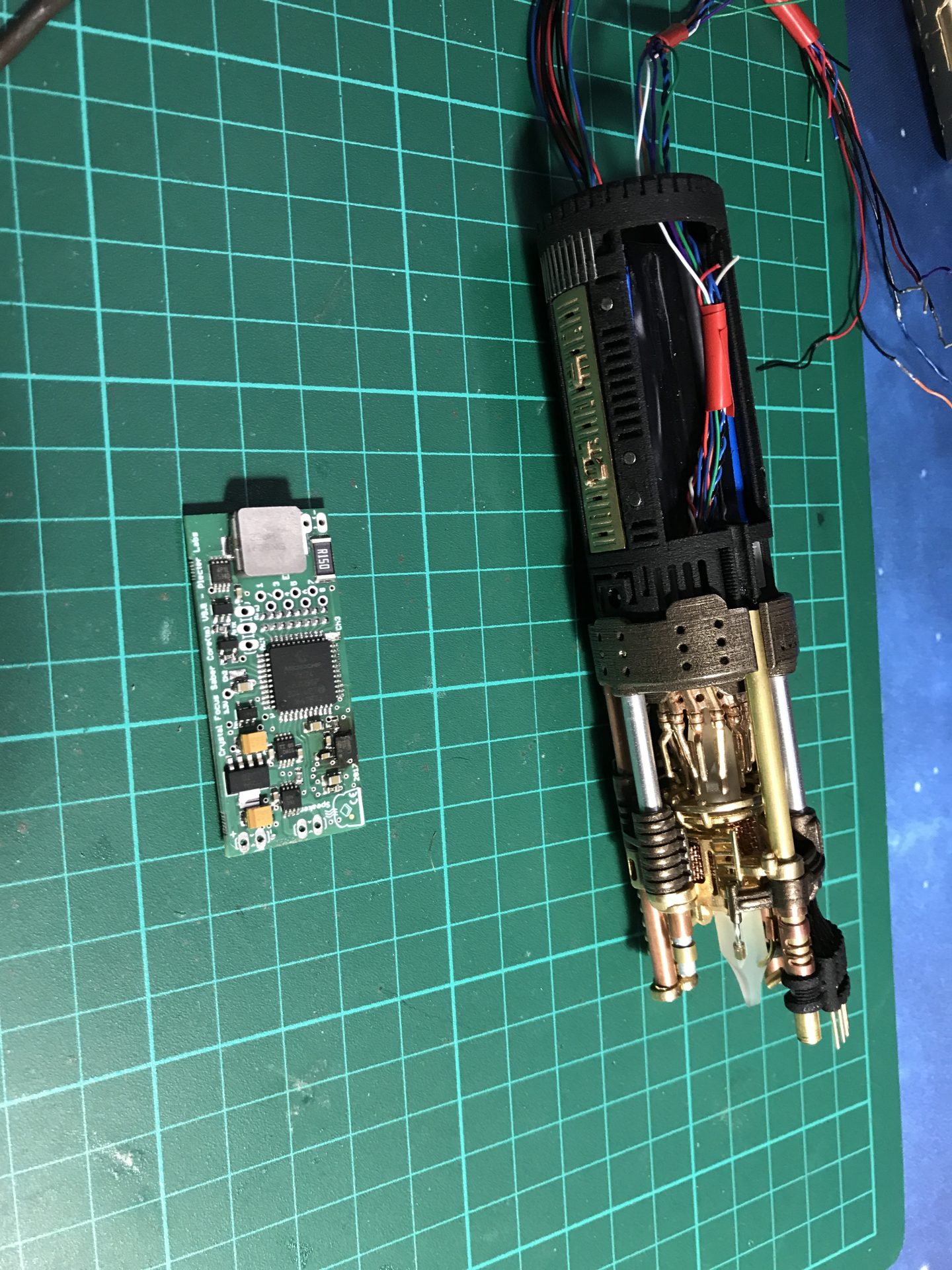
⇒ Soundboard, the “heart” of our sabers is the Soundboard::
Plecter Labs – Crystal Focus 9 + Color Extender
Naigon Elelctronic Creations – I3
⇒ Battery: 2 x 14500 7.4v pack for CF9, you can build a 2 x 14500 3.7v pack for I3
⇒ Recharge Port: only on Variant1, 1.3mm port => High Amp models.
⇒ Battery charger, according to the battery voltage used.
⇒ Main Led: Variant1: Tri-Cree XPE-2 recommended
⇒ Motor, only on Variant1, for the rotative Crystal Chamber: 206-108-6mm-dc-gearmotor-21mm-type
⇒ Brass connector pins, bulgin SA3180/1 and SA3179/1 (ex Digikey: males and female)
⇒ Switches, on the blade holder:
– main is this model of Brass Tactile, with 2mm plunger.
– slide switch => this model for part2 Style1 or the comme 3x6mm tactile switches for part2 Style2.
⇒ On / Off Switch => this kind of High Amp Kill Swithc models.
⇒ Speaker, 28mm flat speaker
⇒ Accent Leds, 2 x 5mm led for the Crystal Chamber recommended (if RGB, read your soundboard manual to select between common anode or common cathode led), 1 x 5mm in the front section, and 4 x 3mm leds for the others.
⇒ Wires, we strongly recommend PTFE wires, as the insulation is thin while still able to handle current very well. You can find them from this eBay shop for example. Use the smallest AWG size possible:
– Tri-Cree install => 30awg for eveything
– Neopixel install => 32 awg wires for everything except Battery and Neopixel strip + and – (24awg PTFE).
⇒ Heat shrink tubing, to protect your joints.
⇒ RICE port – an optional custom RICE port can be built (to be detailed later)
⇒ 7/8″ OD Blades (for NerfworXlab Blade Holder) or 1″ OD blades (for TGS and KR Blade Holders).
Demo:
DIY Instructions:
Disclainer:
– These instructions will details the install procedure as much as possible. GOTH-3Designs cannot be held responsible for any mistakes made by DIYers.
– Always wear protective gear when working on install (gloves, eye protection, …), GOTH-3Designs cannot be held responsible in case of accident.
Note 1: This is an expert build. Commission an installer to build the hilt for you, if you feel unsure about what to do.
Note 2: These instruction will cover the Plecter Labs CF9 install, however we do not cover wiring instructions tho, please read your soundboard manual before starting the install. NEC I3 install procedure is similar.
Note 3: 30awg wires and smaller are mandatory for this install (30awg for main wires and 32awg for accent leds and switches are highly recommended).
Note 4: The install can be done with any of blade holder available. These instructions are done with NerfworXlab’s Deluxe V1 Blade Holder.
Note 5: This kind of chassis isn’t meant for dueling. Display or Cosplay only.
Note 6: We also cover the Vintage Graflex Flashgun conversion in the following instructions for Variant1. Flashgun replica will be similar.
Note 7: These install instructions are made with a prototype, some details changes can be found with the final product.
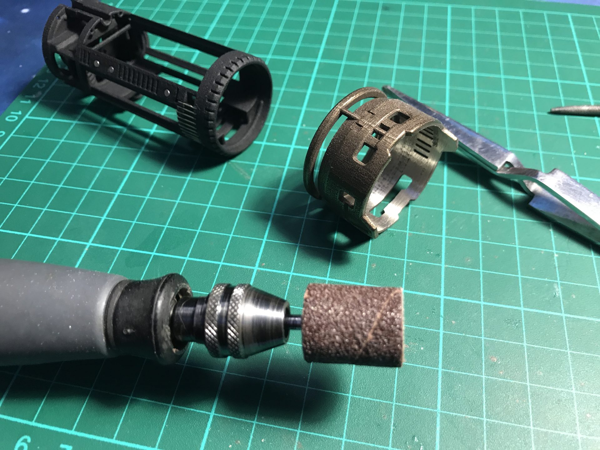
Note 8: When using steel material, it can be optionally sanded until obtaining a smooth surface. Here is an example using the same “Polished Bronze Steel material”, sanded on the left and raw on the right. We did not polish the steel on the following instructions as we liked the color contract and rough steel, but know that it is possible and you can check our YouTube channel for the prototype#2 demo with sanded parts.

Note 9: Recharge port wiring reminder:

VARIANT1 DIY Instructions
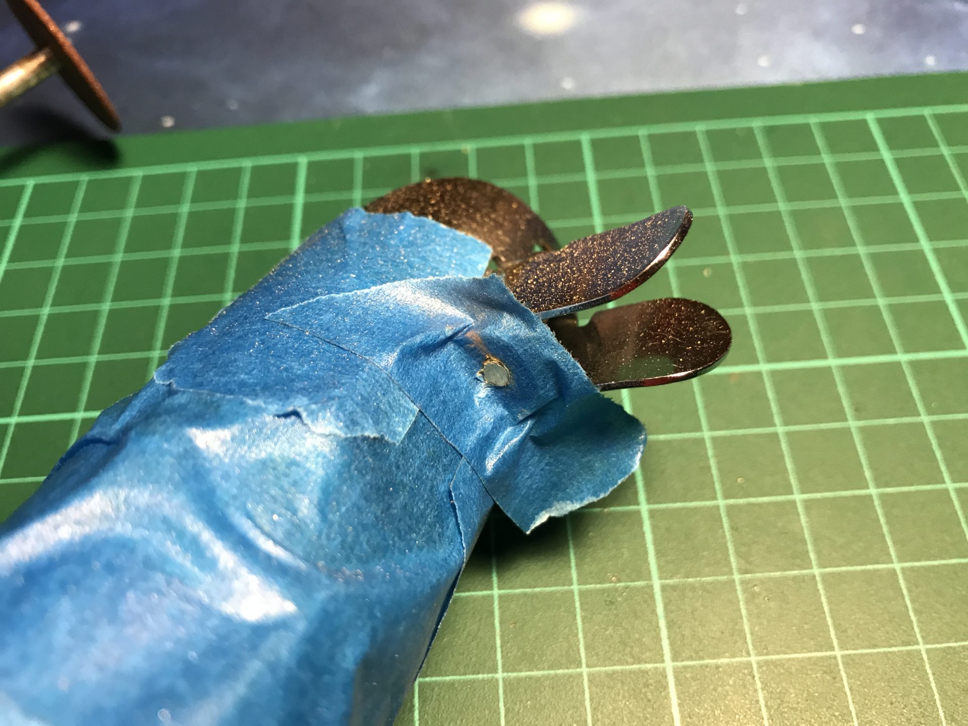
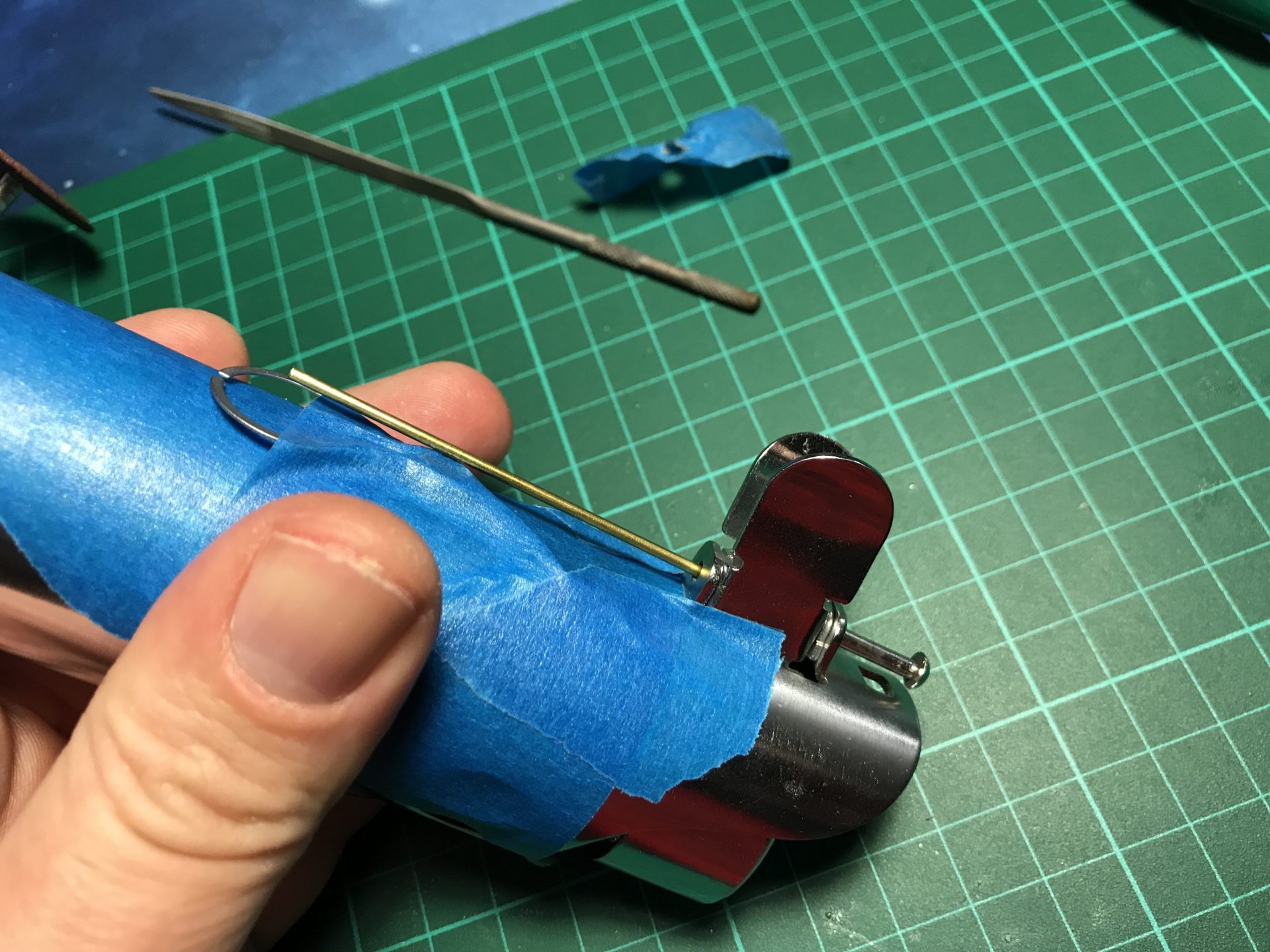
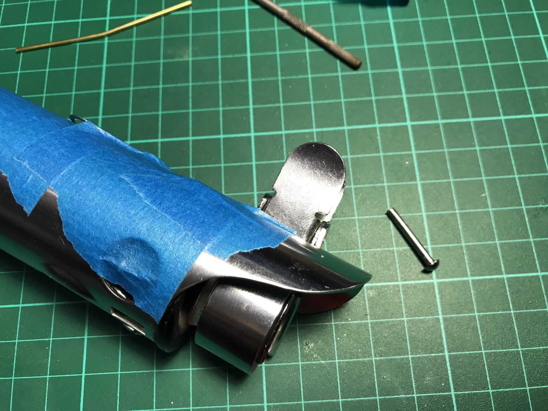
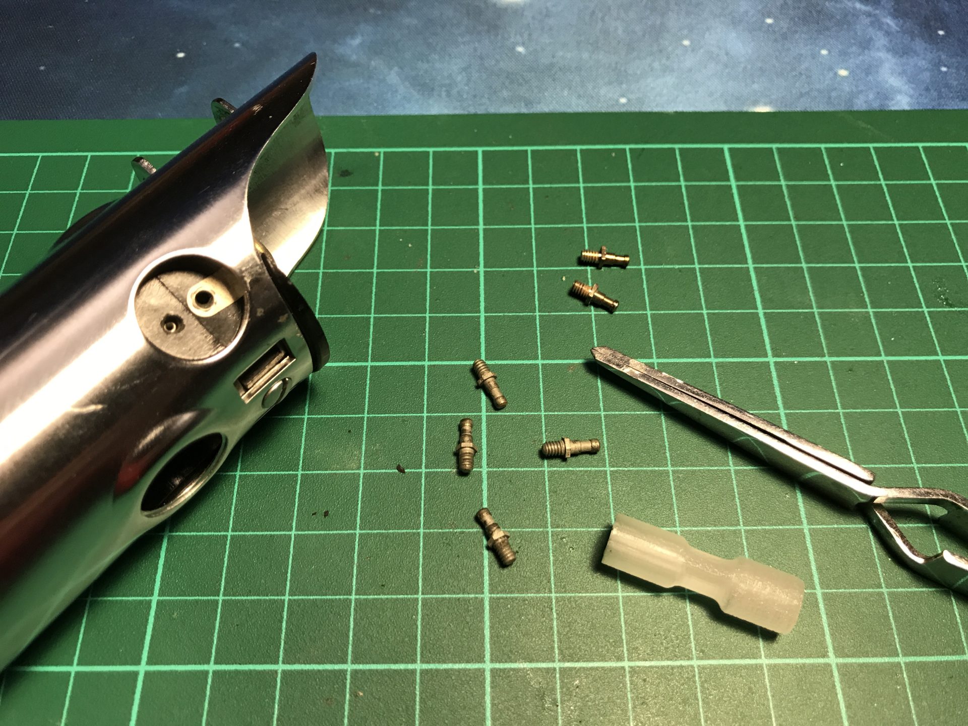
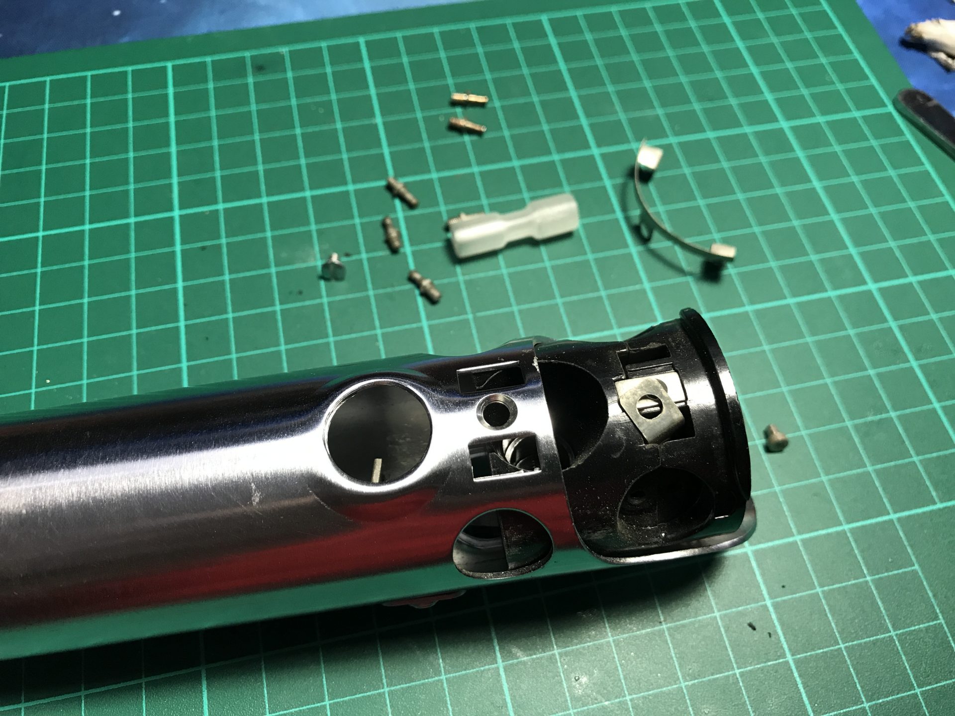
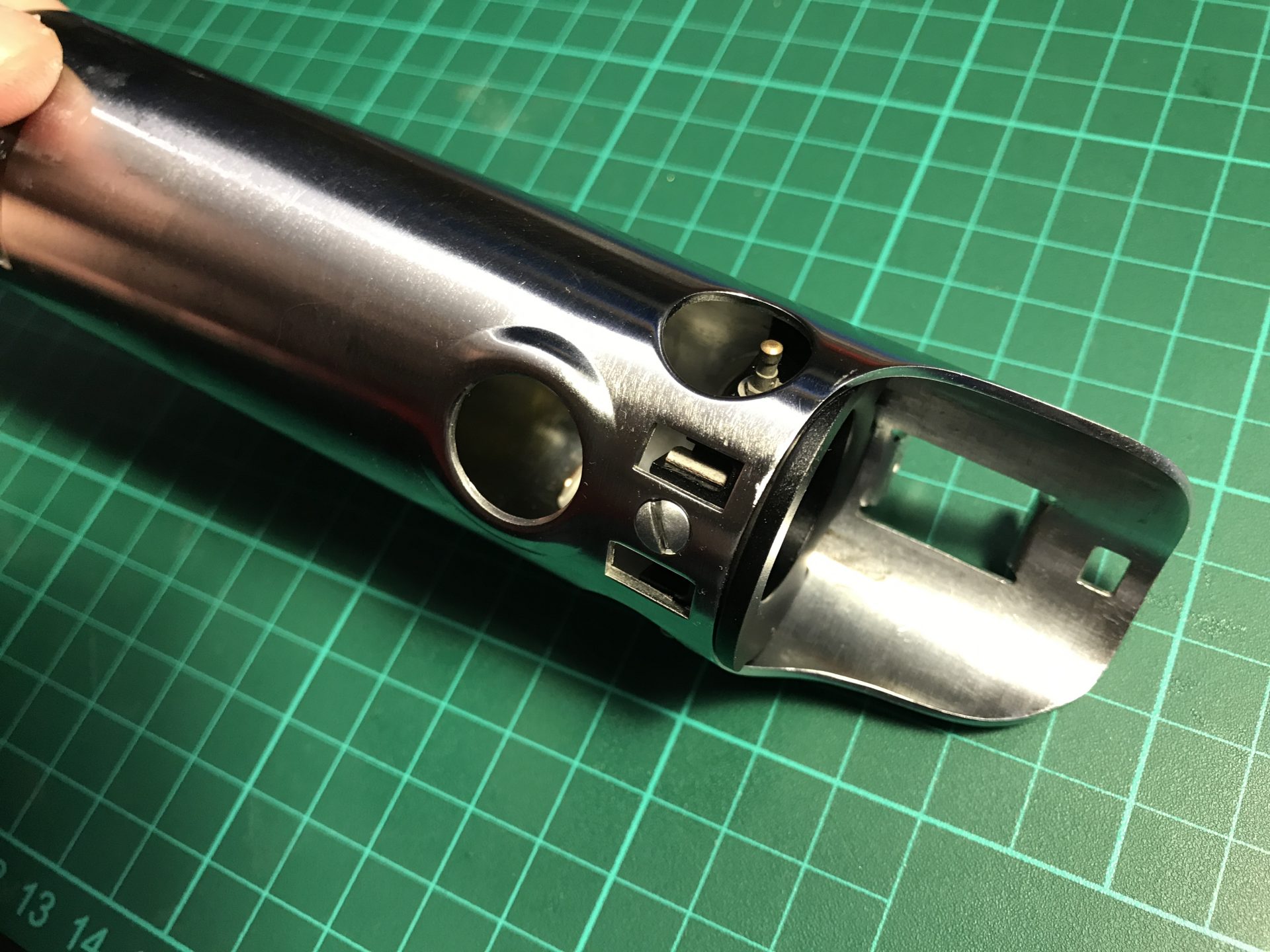
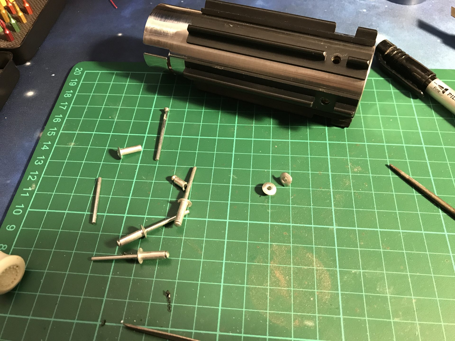
Step 1: Vintage Graflex bunny ears pin removal. To be done with care and patience, remove the red button, protect the hilt and file down the pin in order to be able to push it out. You can eventually use a rod to softly hammer the pin out, and remove the bunny ears.
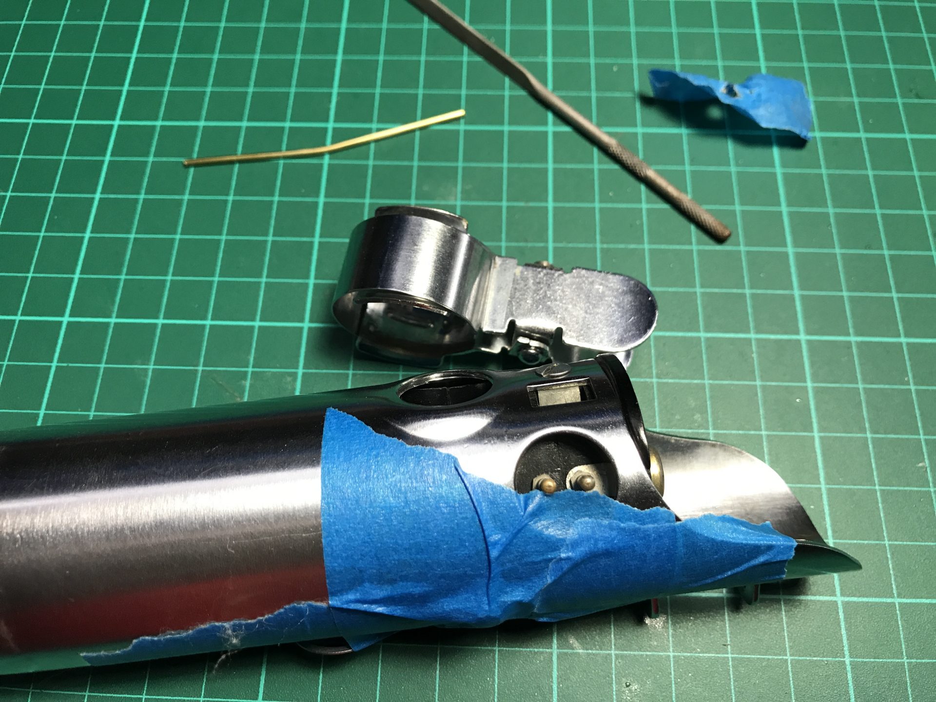
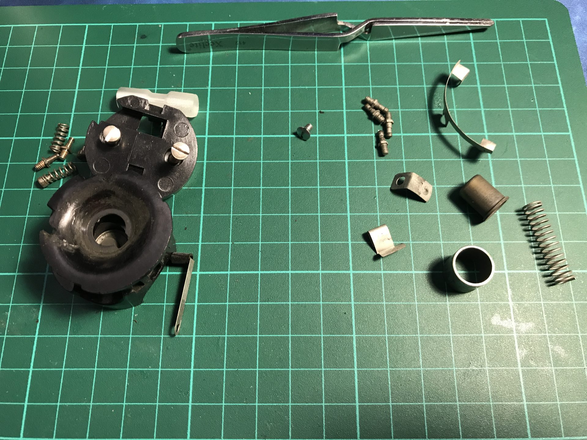
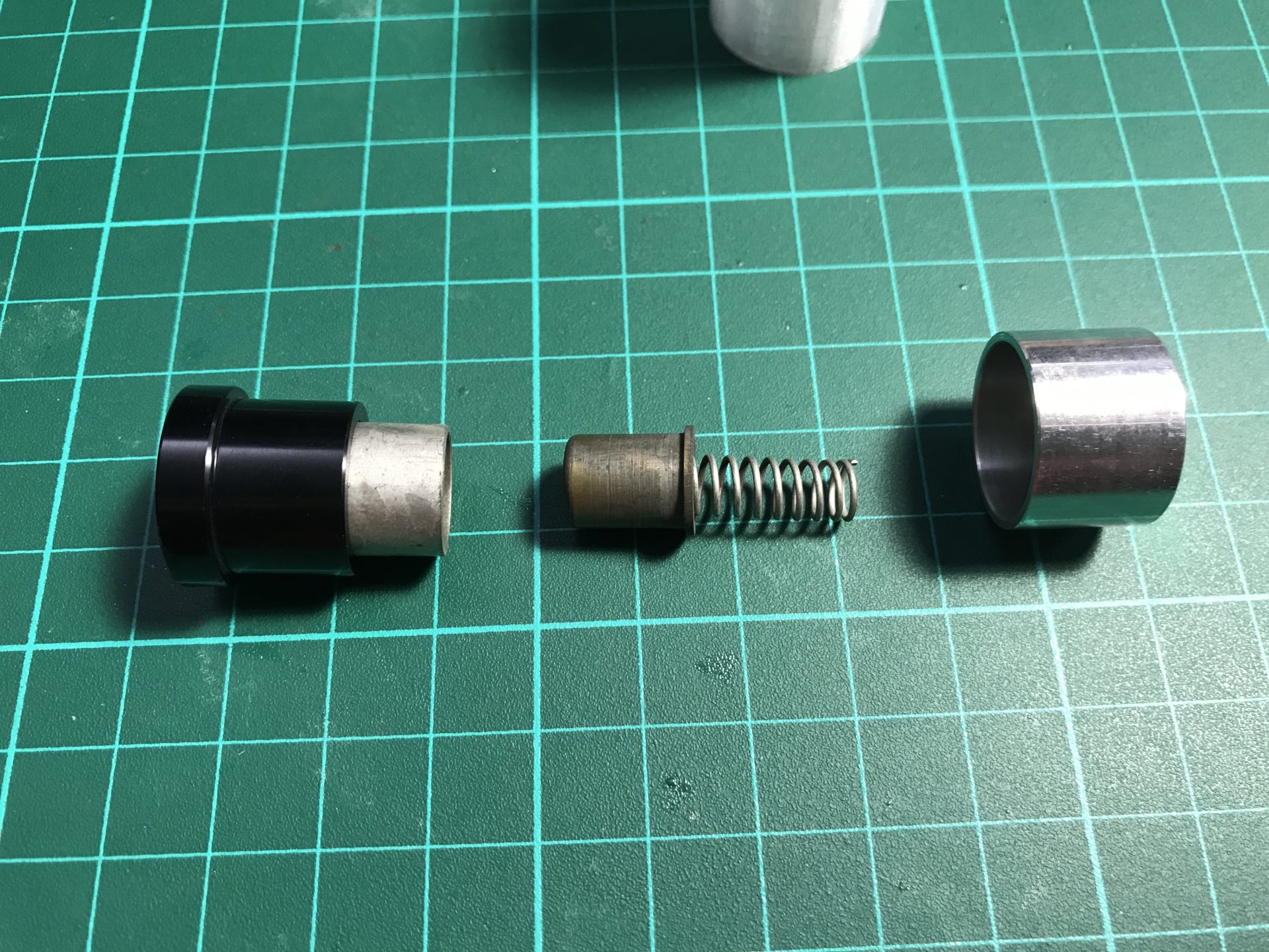
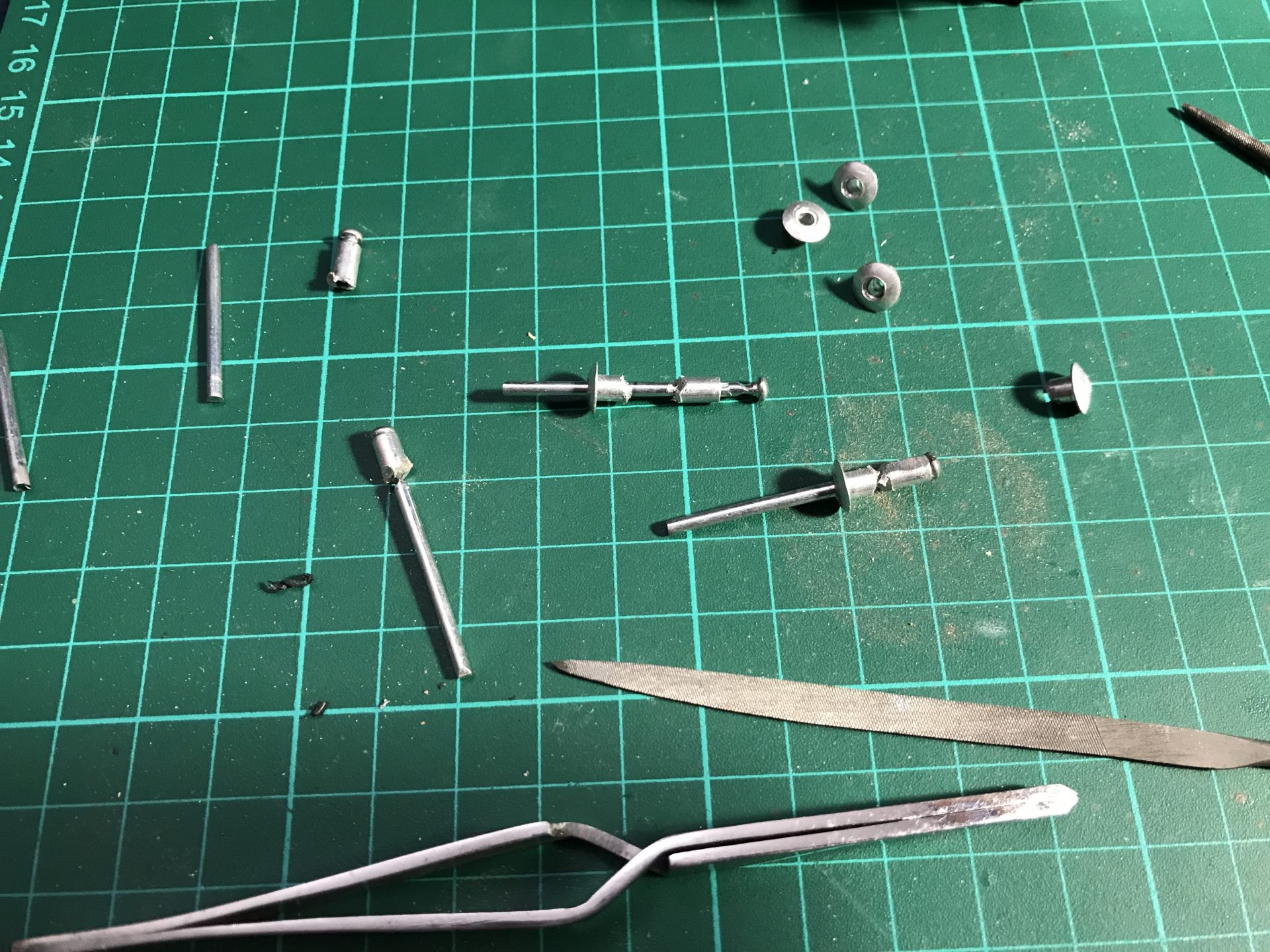
Step 2: Remove the brass pins (using a pin removal tool (available at our shop), and push out the bulb assembly. You can then dismount the assembly to recover the part in order to make your blade holder accurate.
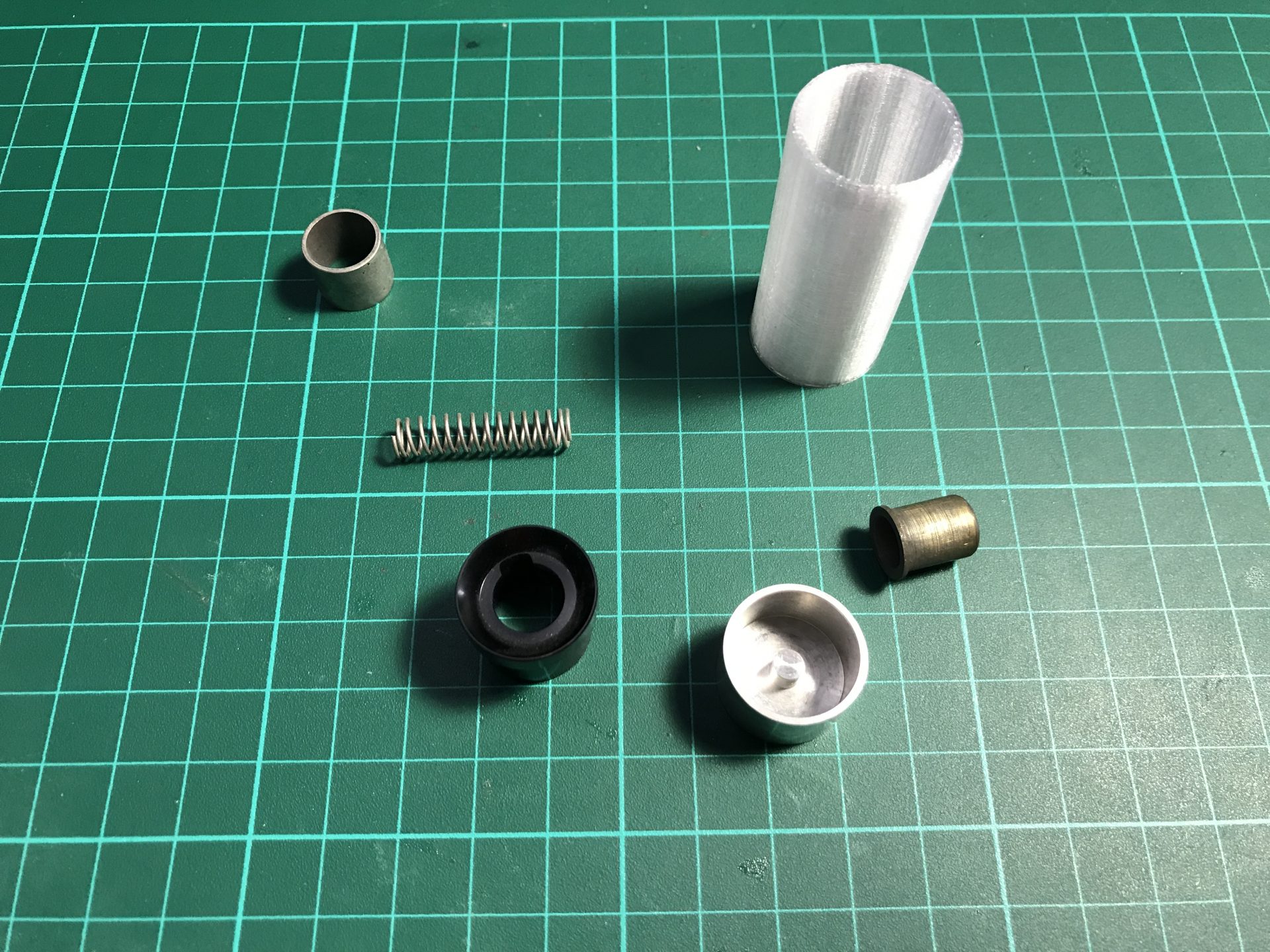
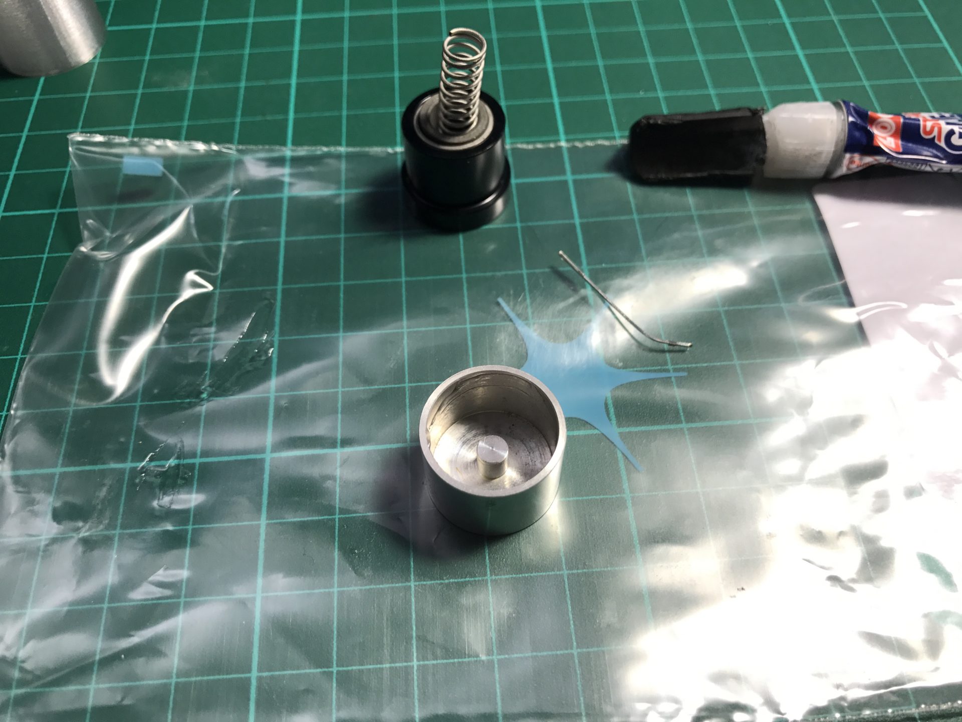
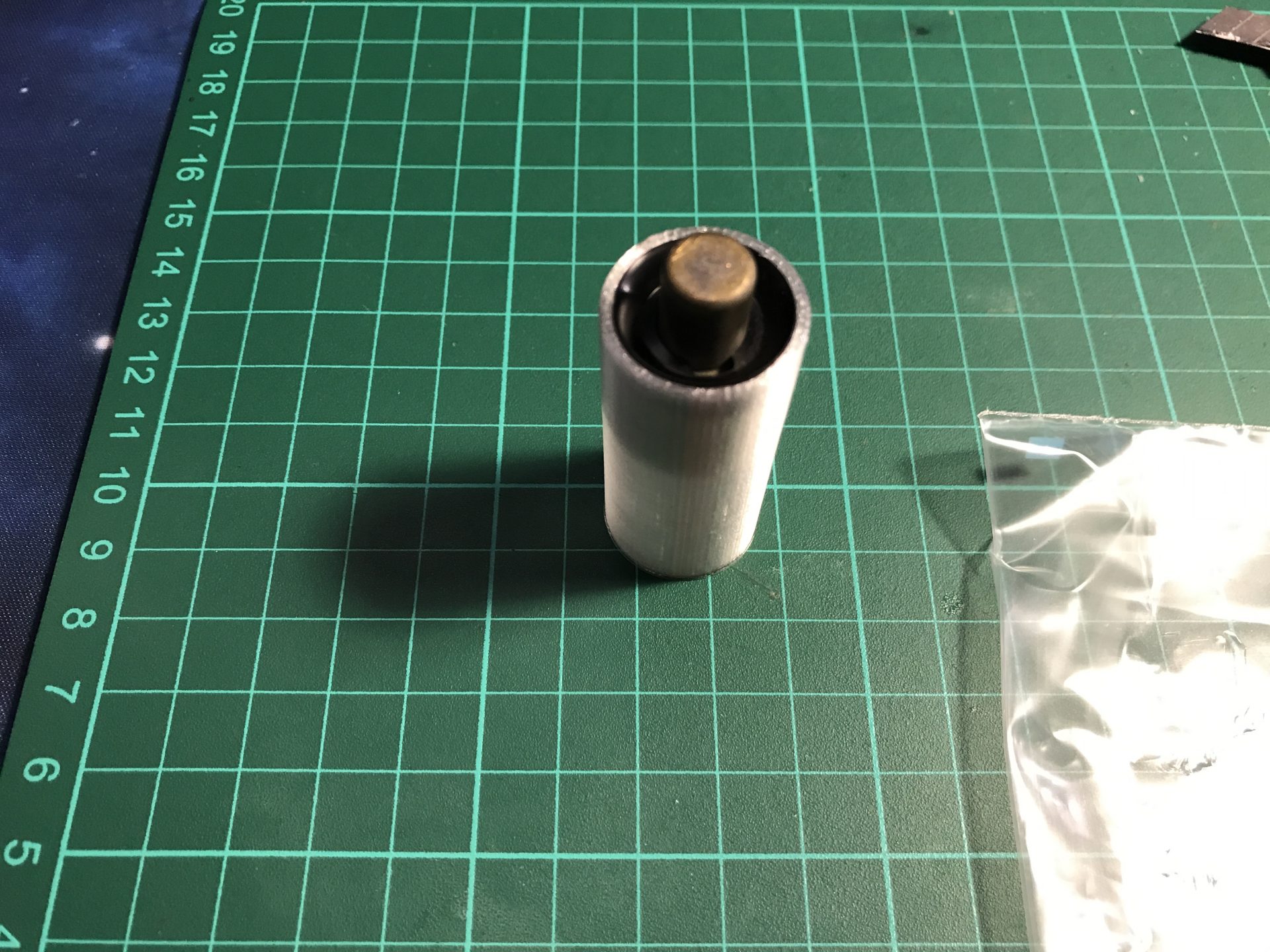
Step 3: The NerfworXlab blade holder come with part to rebuild the spring loaded brass bulb contact, and make a blade plug out of it (3D printed tube also available on our shop). Assemble it as shown blow and glue the 2 parts together.
Step 4: You can also cut the electrical contact to glue them on the blade holder and add more vintage accuracy to your hilt.
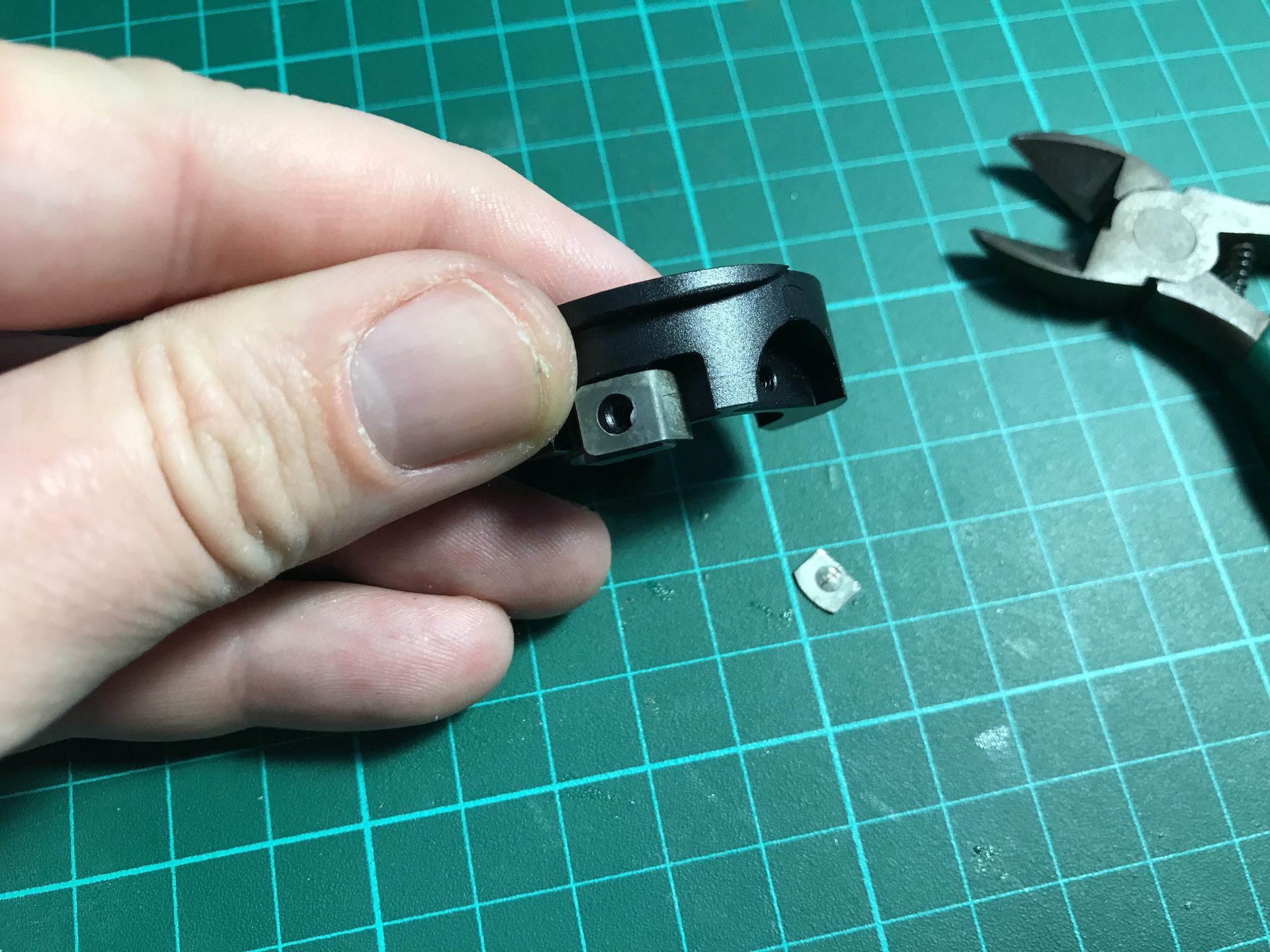
Step 5: The slider switch tab needs to be cut down. We first sanded carefully each border until it could be easily broken by bending the tab. Then sand down the tab until it fits perfectly when inserting the blade holder lower part.
Step 6: Now fit together the 2 parts of the blade holder to check they assemble properly. It might be necessary to carefully hammer the upper part down to avoid a gap in the brass pin socket.
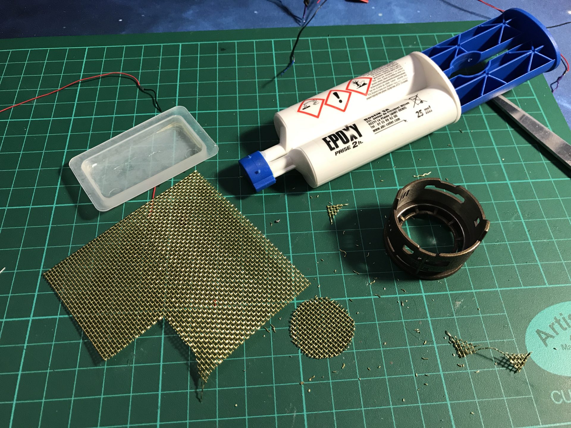
Optional: to make the upper blade holder part secure and prevent it from moving when inserting the blade, we used a bit of epoxy (carefully placed and with the excess cleaned once the part was put in place).

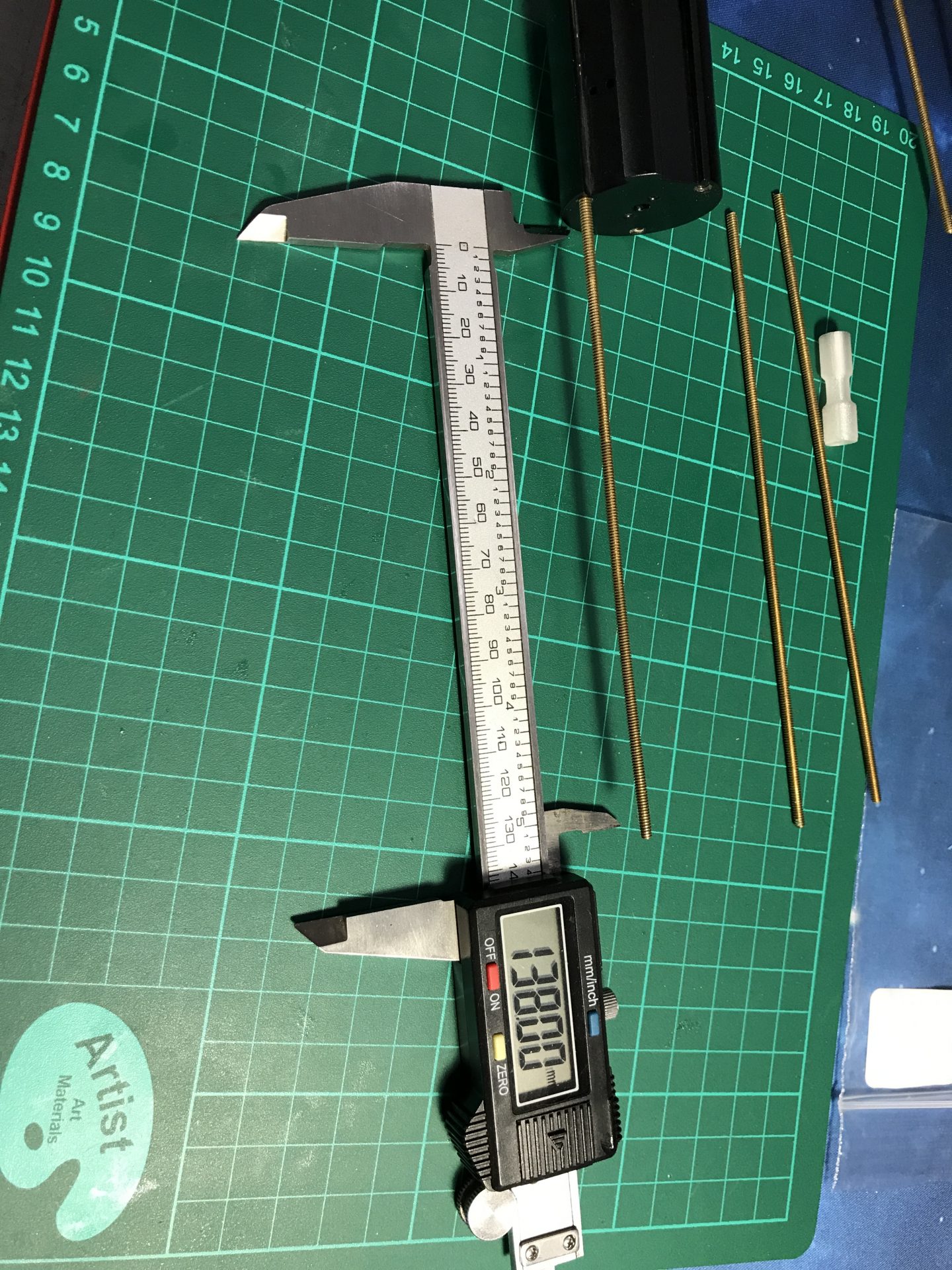
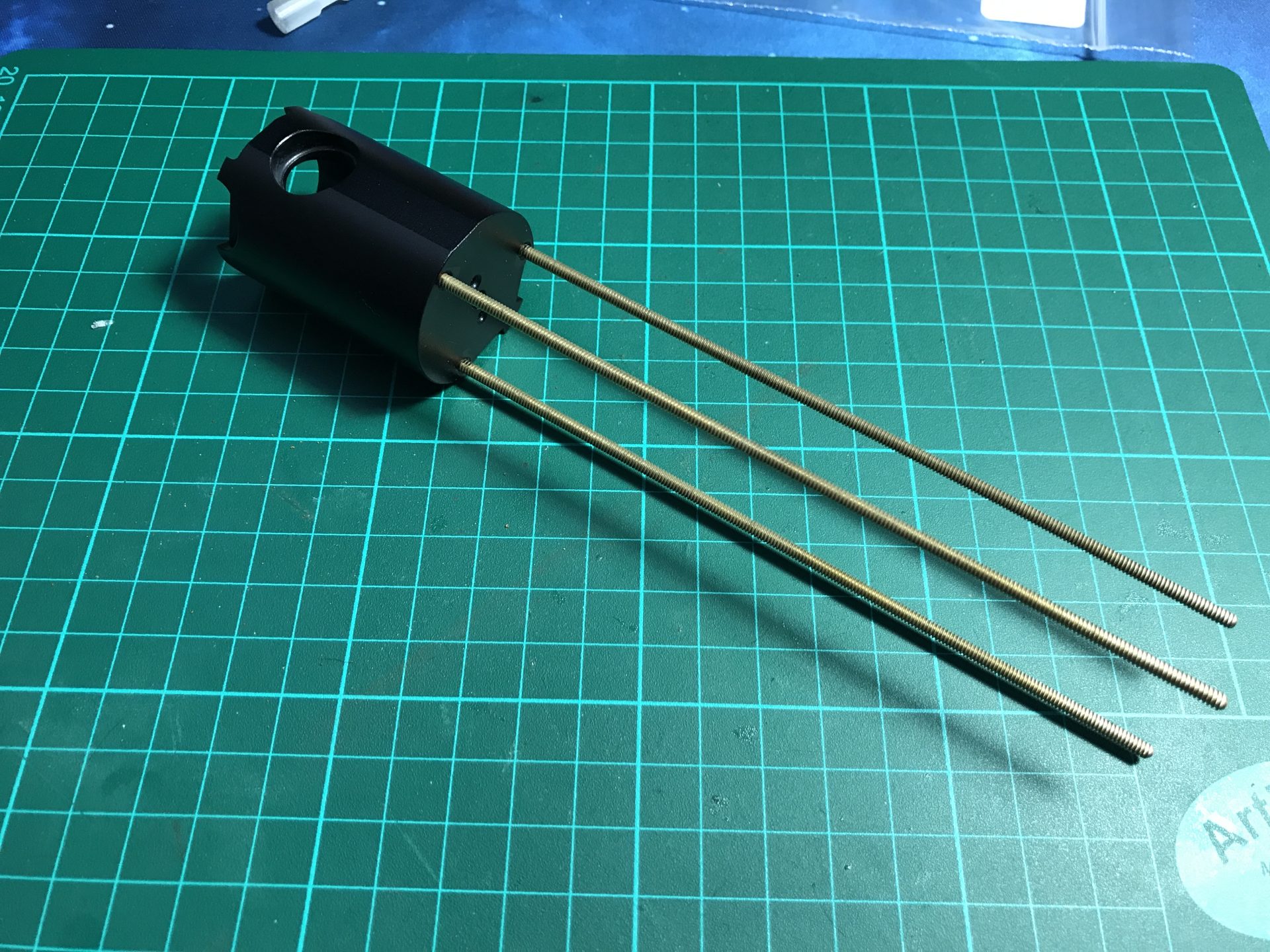
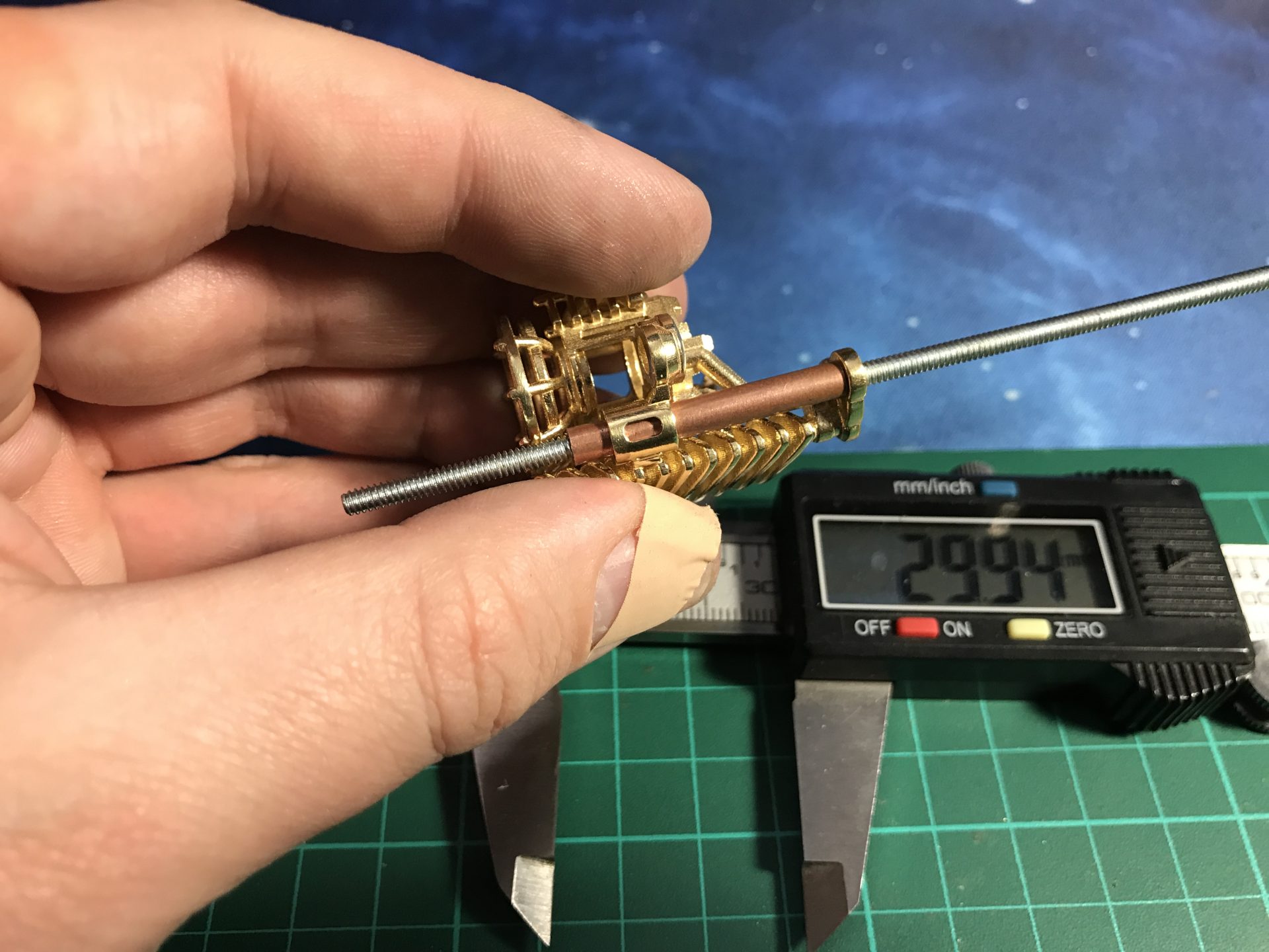
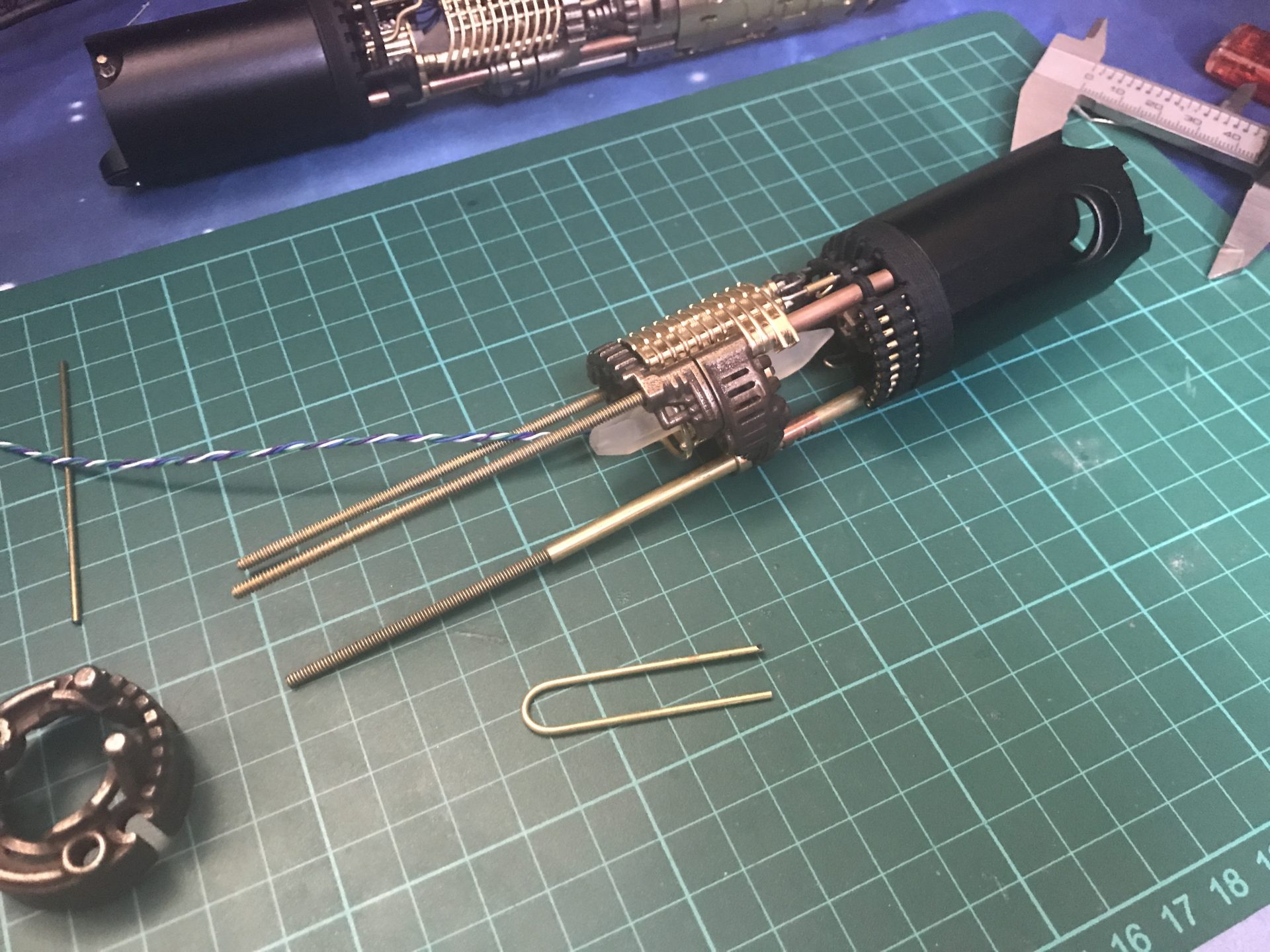
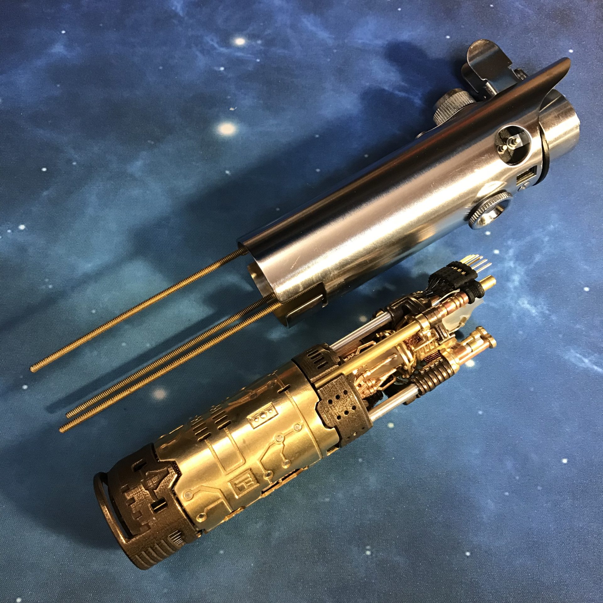
Step 7: Cut the brass threaded rods, the length outside the blade holder must be 138mm, so plan accordingly the additional length to screw them into the blade holder (according to the blade holder used. Make sure the 3 rods have the same length once screwed in (as a test, the blade holder should sit fit on the 3 rods without falling down).
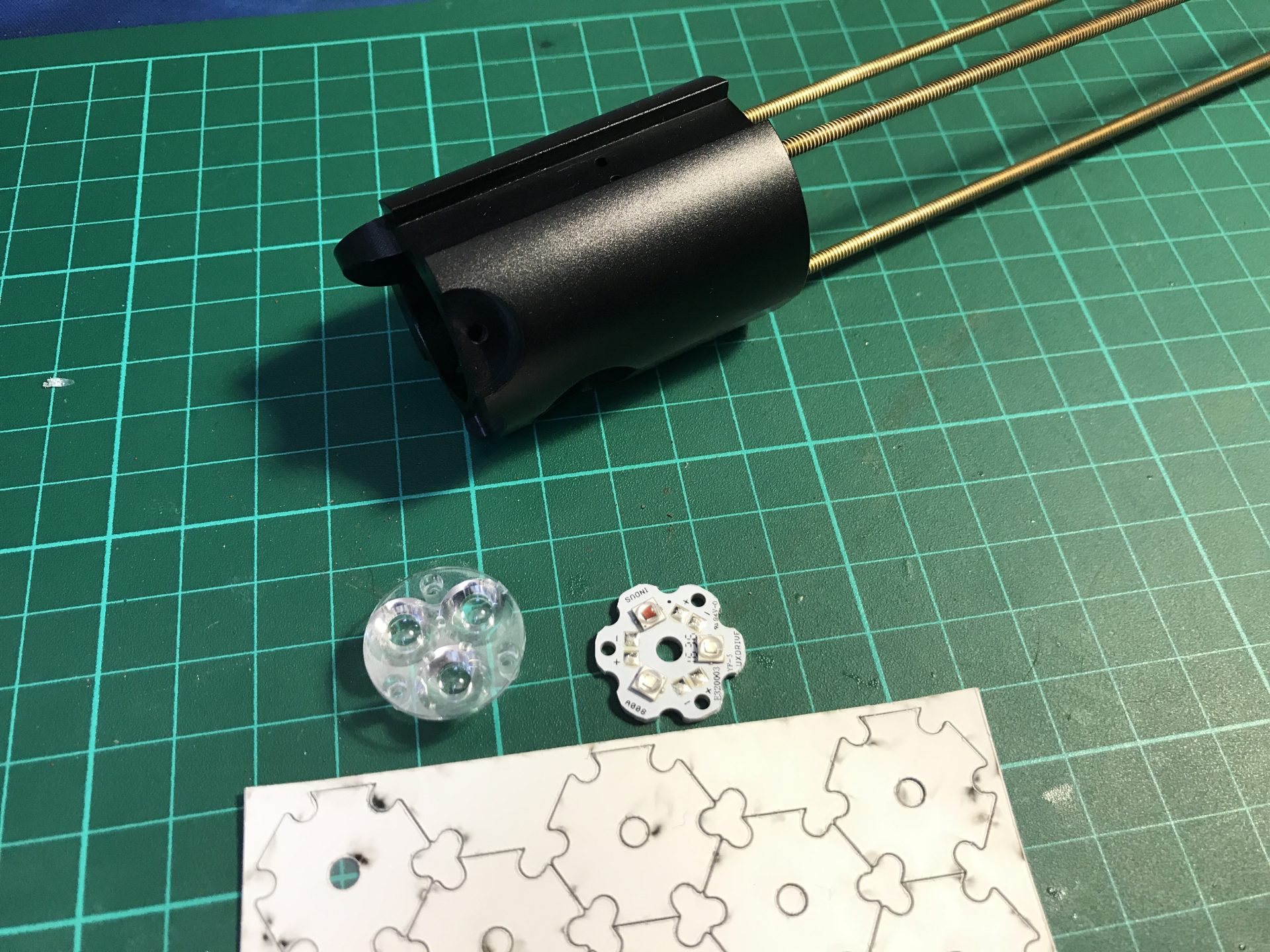
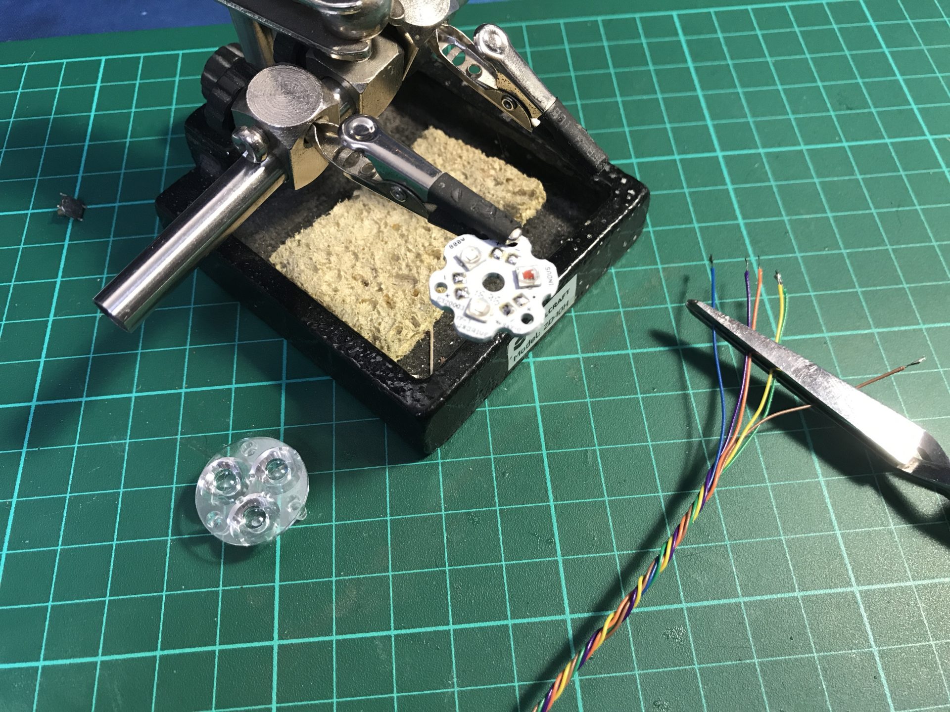
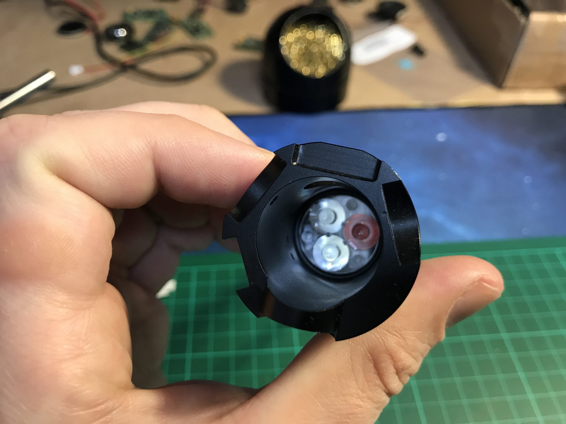
Step 8: Install the main led. 6 wires are soldered for the CF9, then use double tape thermal pad to secure the led into the blade holder. There is no need for a long length of wire here, but give a bit of margin to ease the install later.
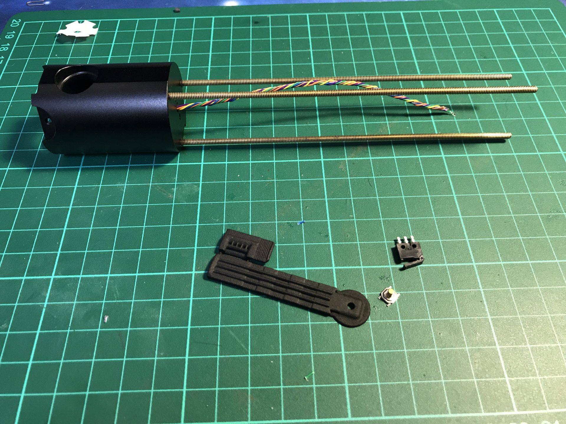
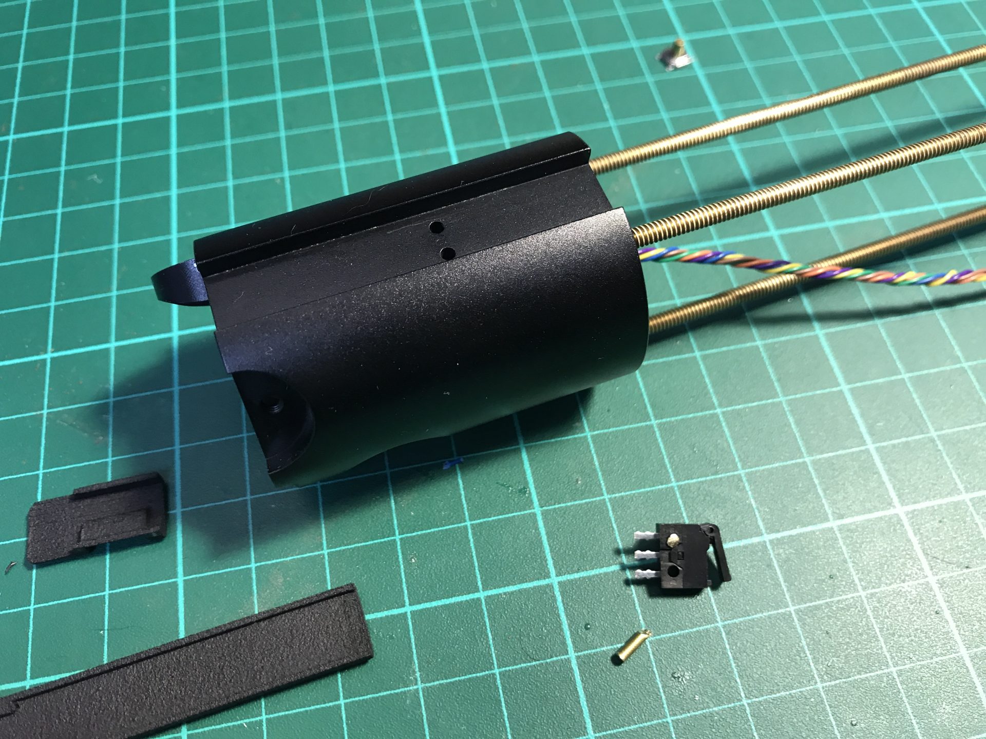
Step 9: Install the slide switch. The optional cover style 1 is used here, with the slider switch (a tactile switch can also be used with a cover style 2).
This switch can be secured using 2 short piece of 1.5mm OD brass rods, as shown below. This help positioning and the switch can be secure with a drop of super glue.
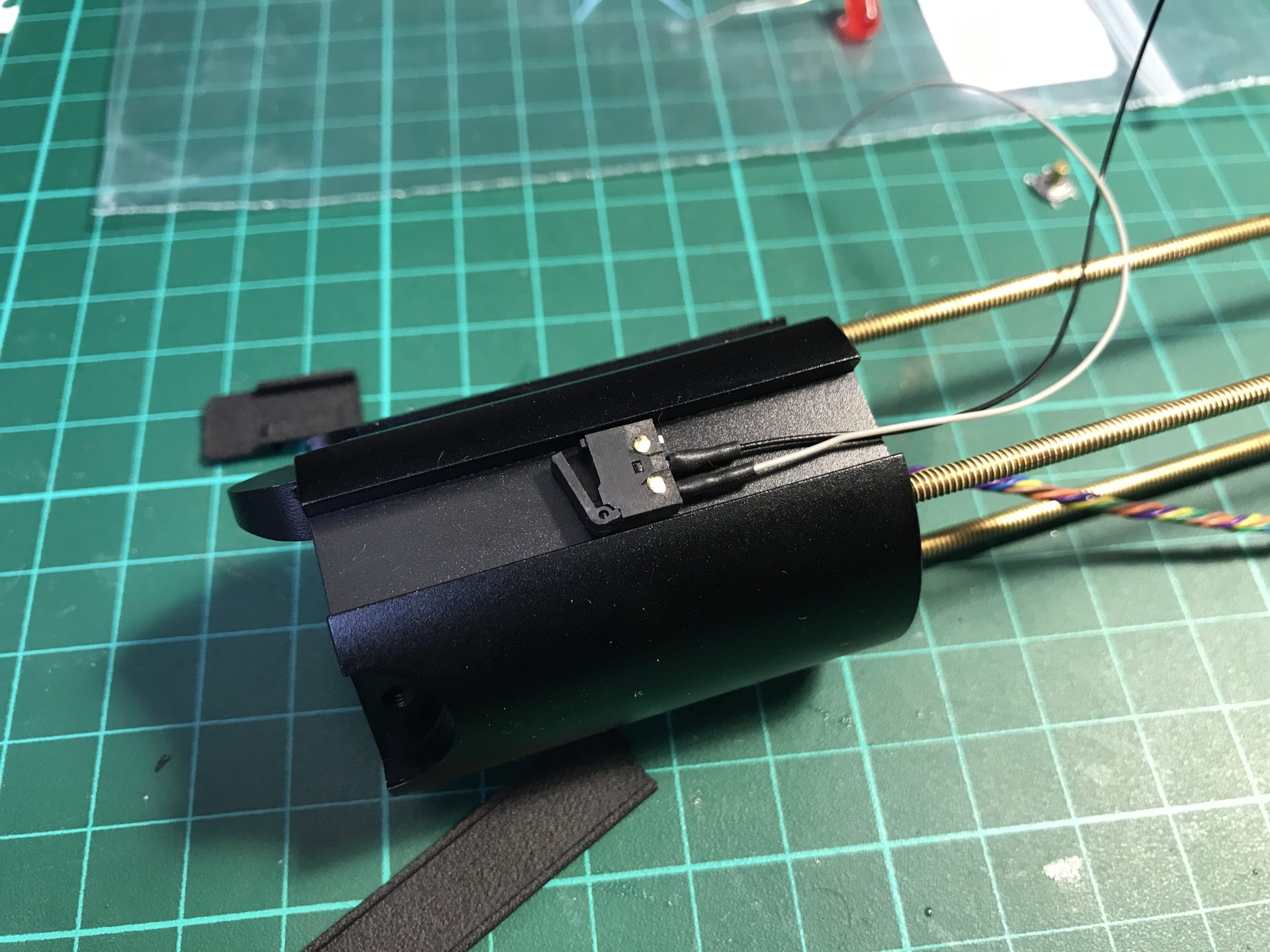
Step 10: Install the main switch, first it needed to be carefully glued on its cover, using a bit of electrical tape for insulation (we used Nitto tape as it can heatshrink). Then glue the assembly onto the blade holder. It is easy to place it using the switch circle as reference.
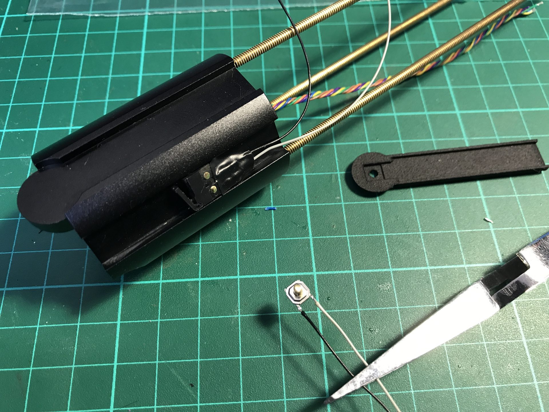
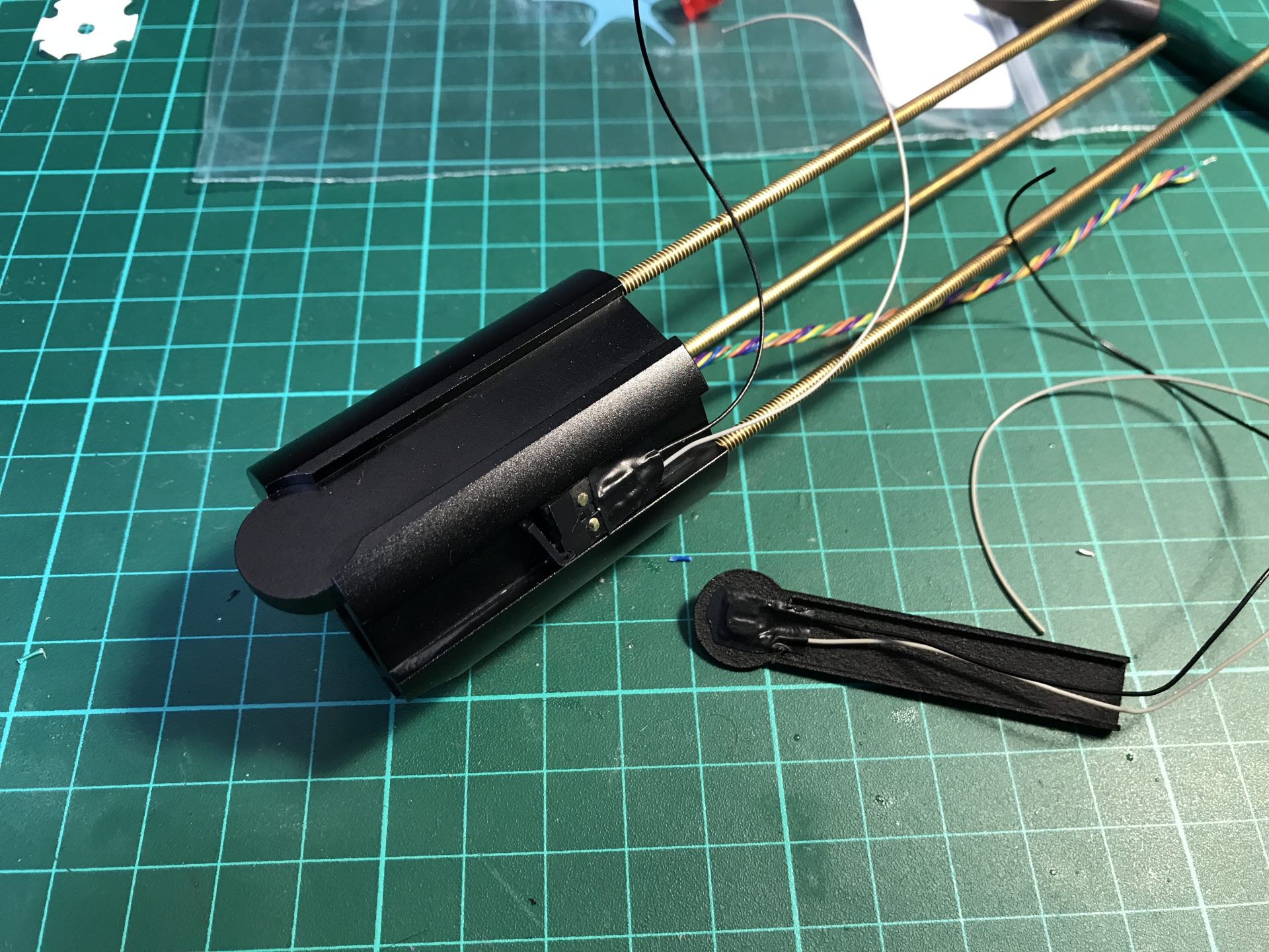
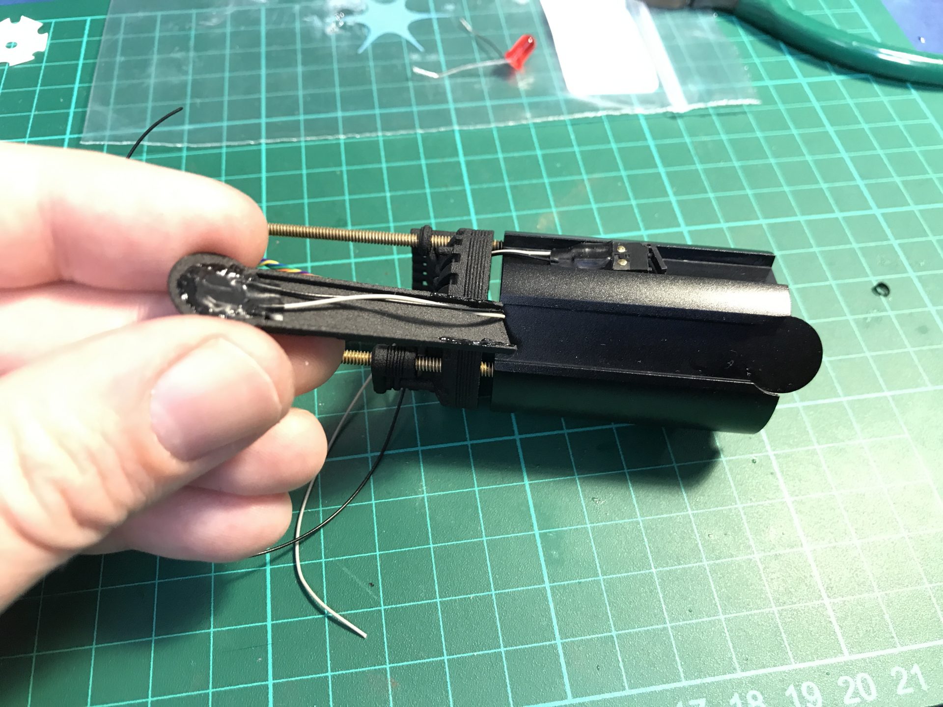
Step 11: Note that the negative leads of both switches and the one of the front accent led need to be soldered together (3 wires into one, to reduce by 2 the number of wires as the connector is limited to 10 wires).
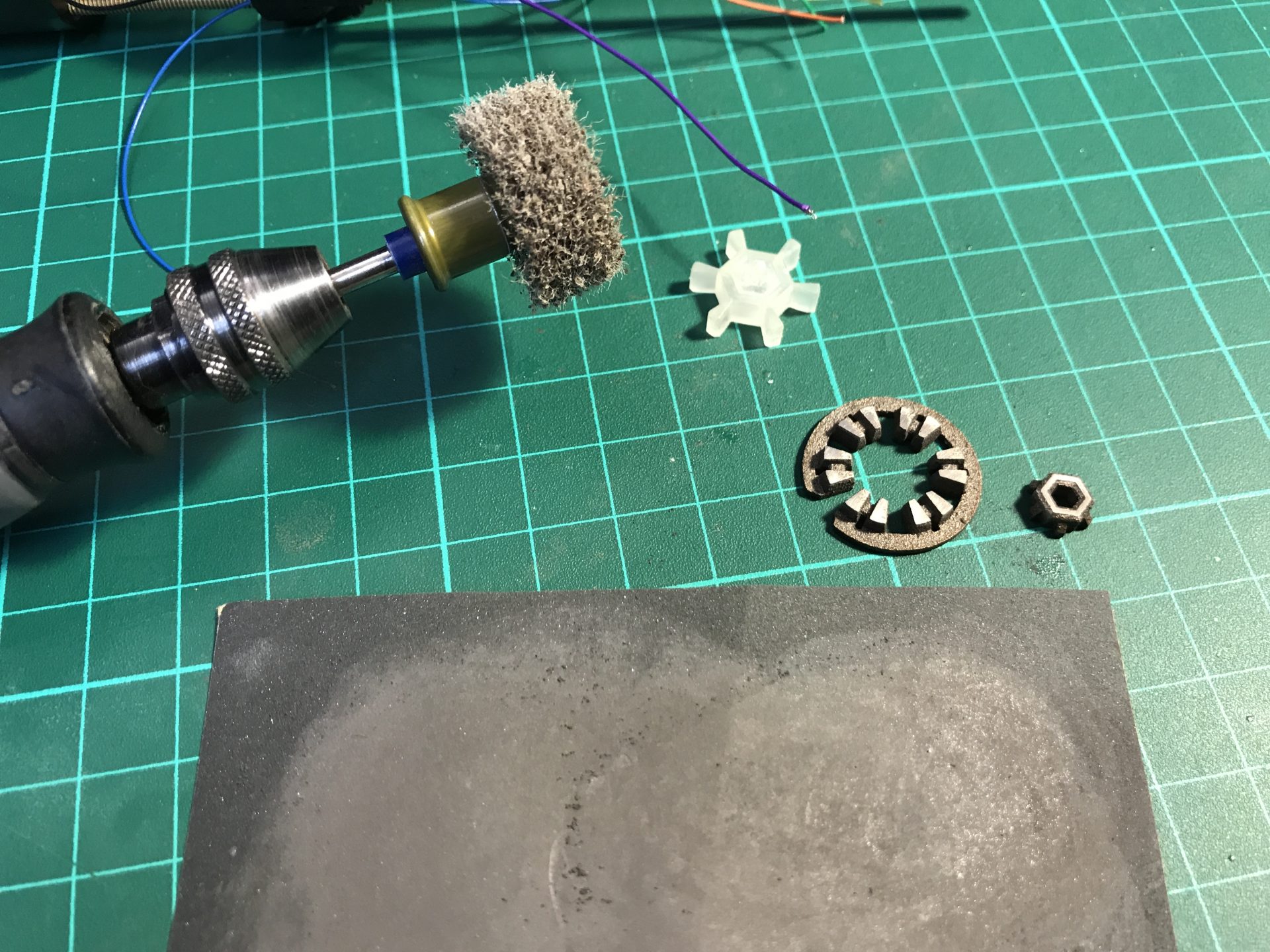
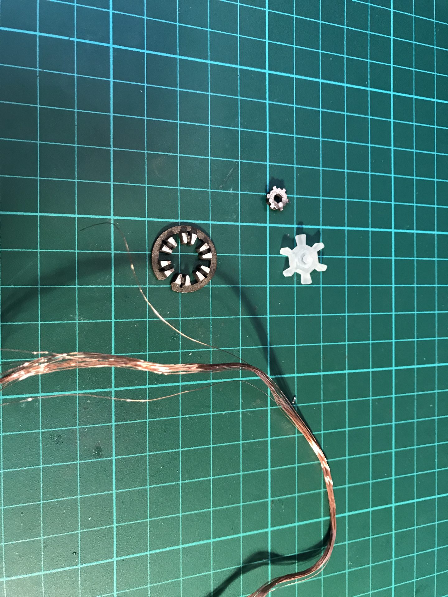
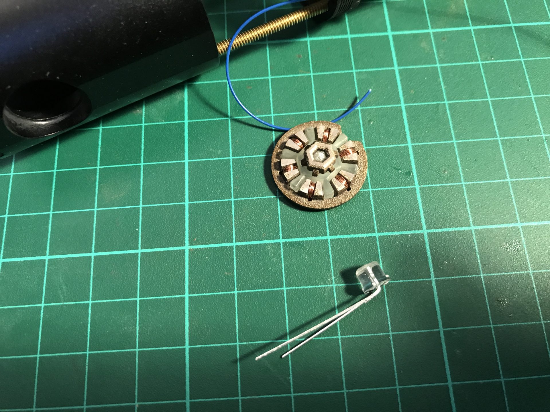
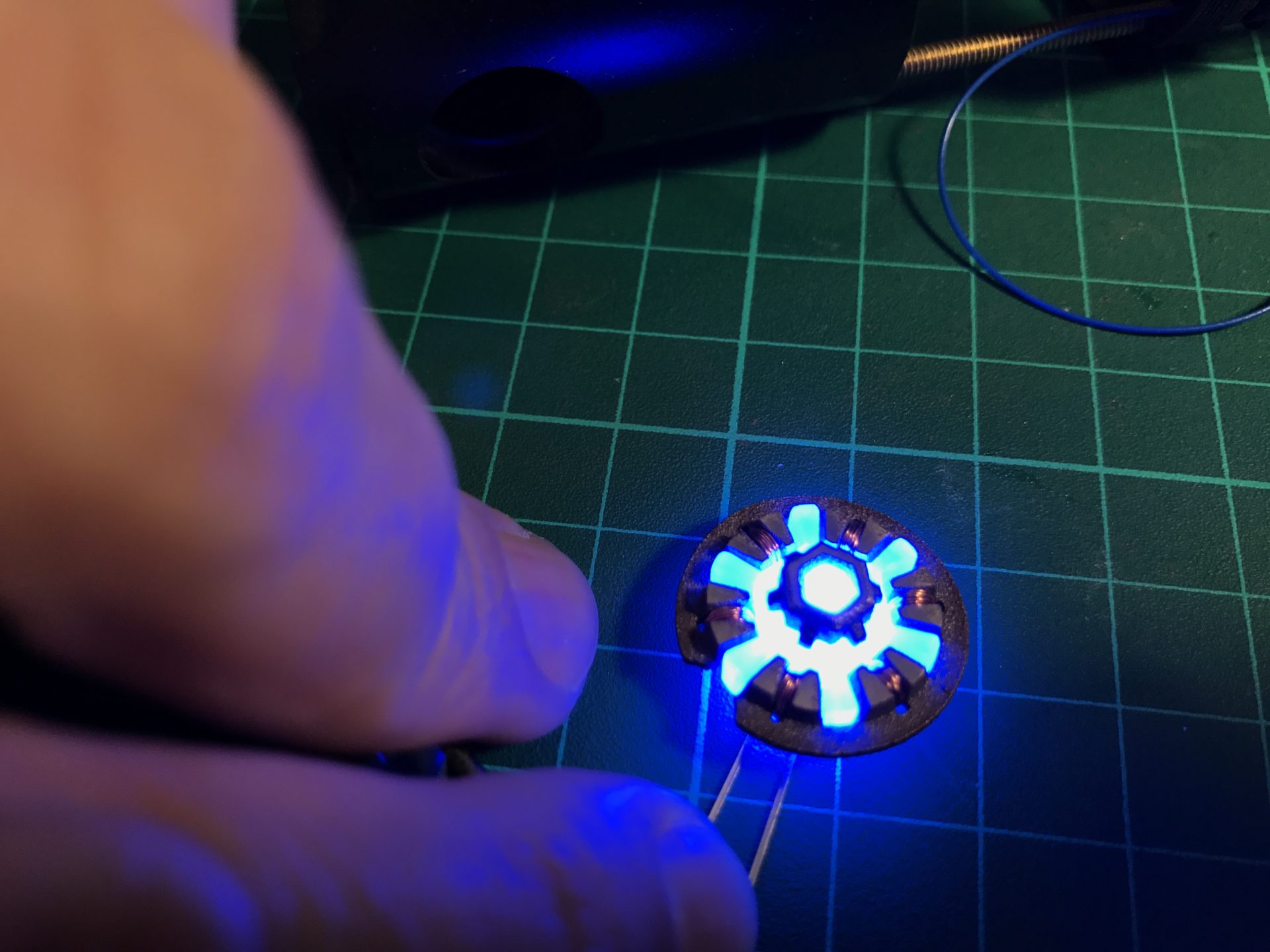
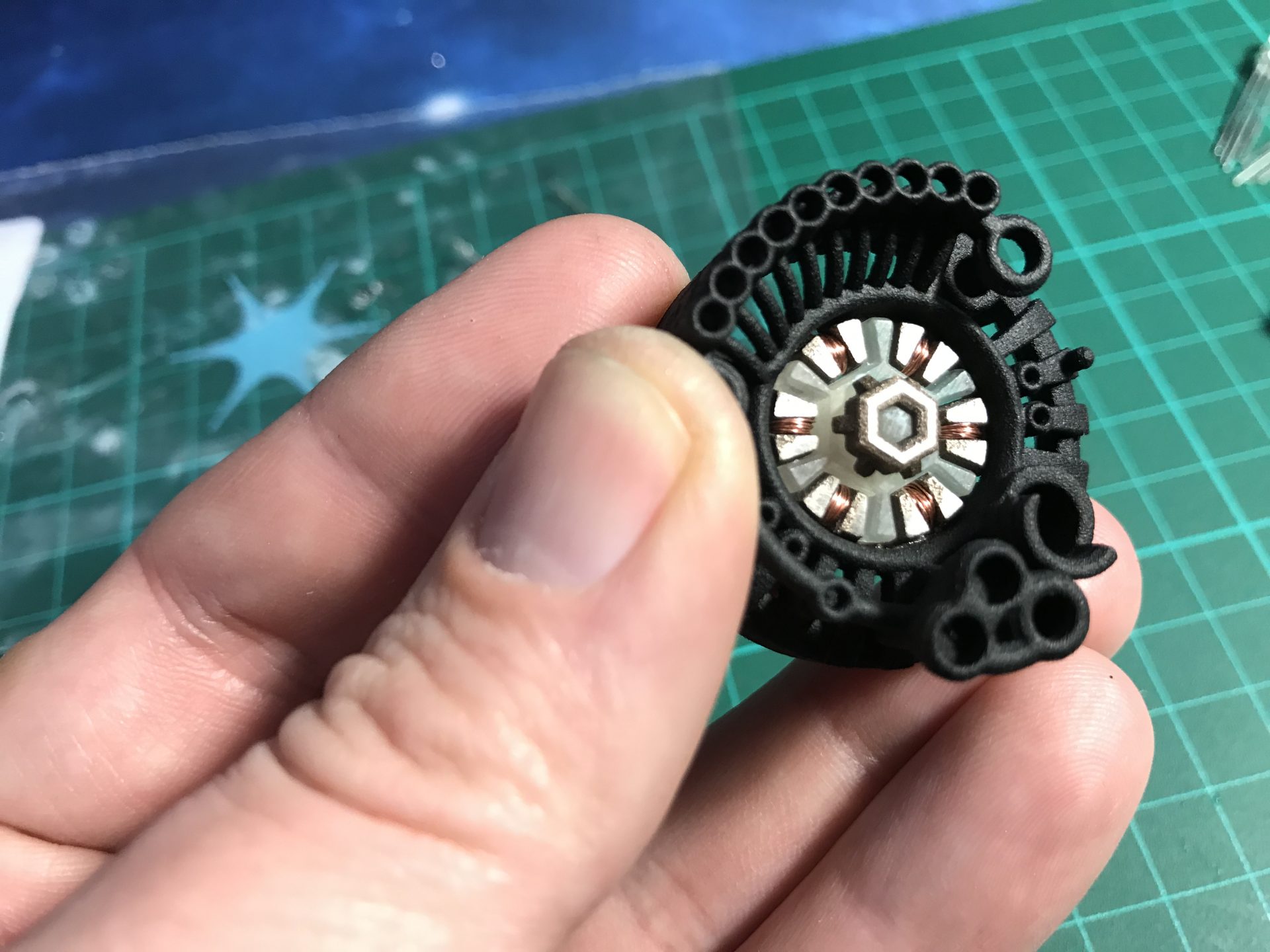
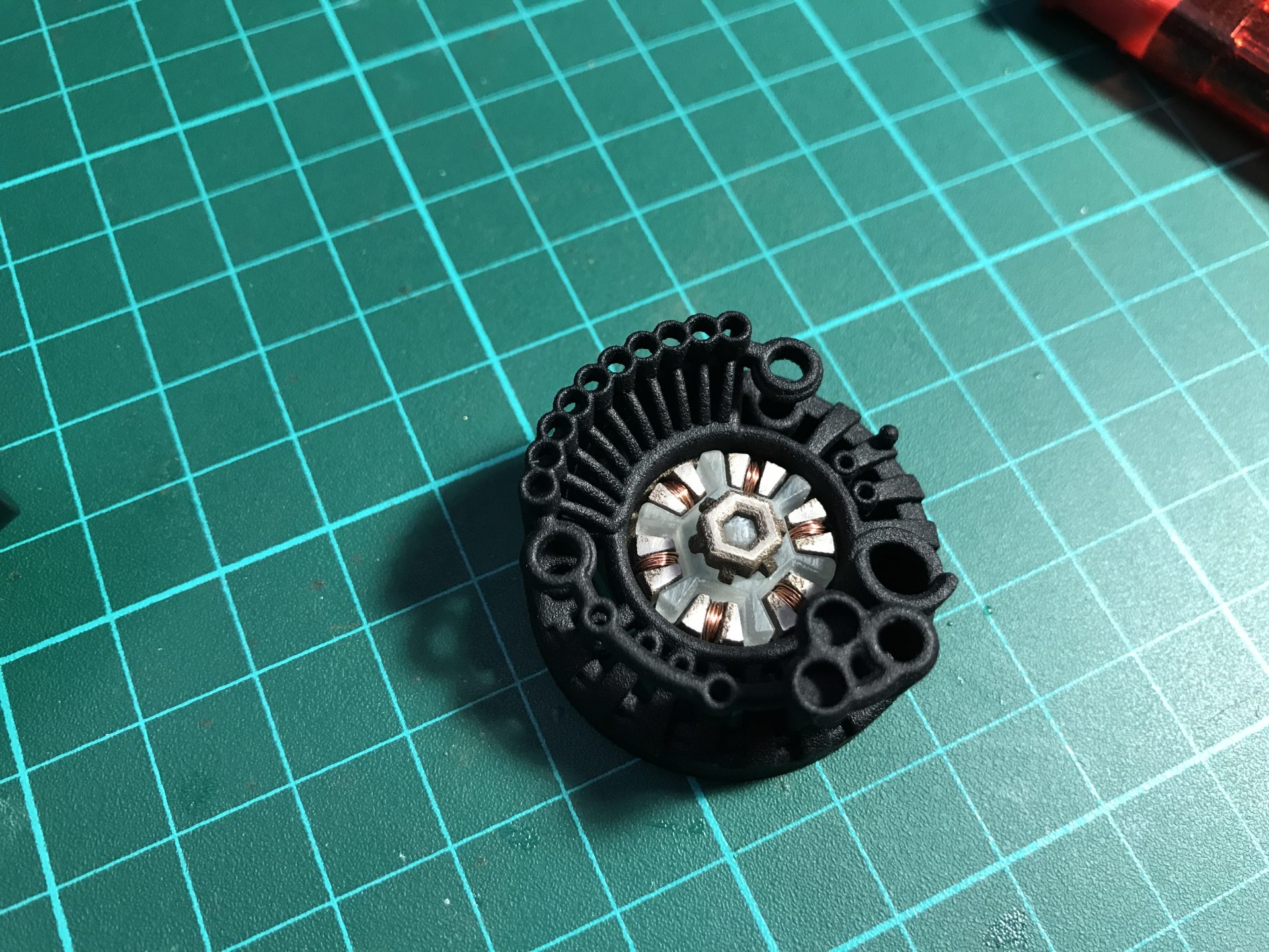
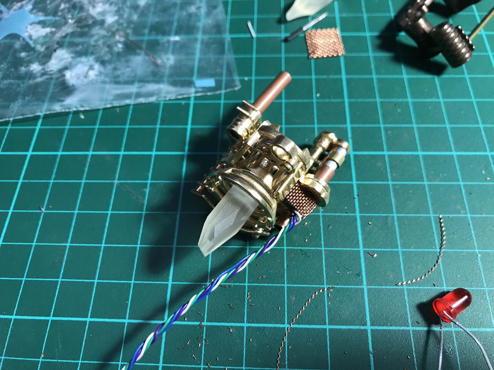
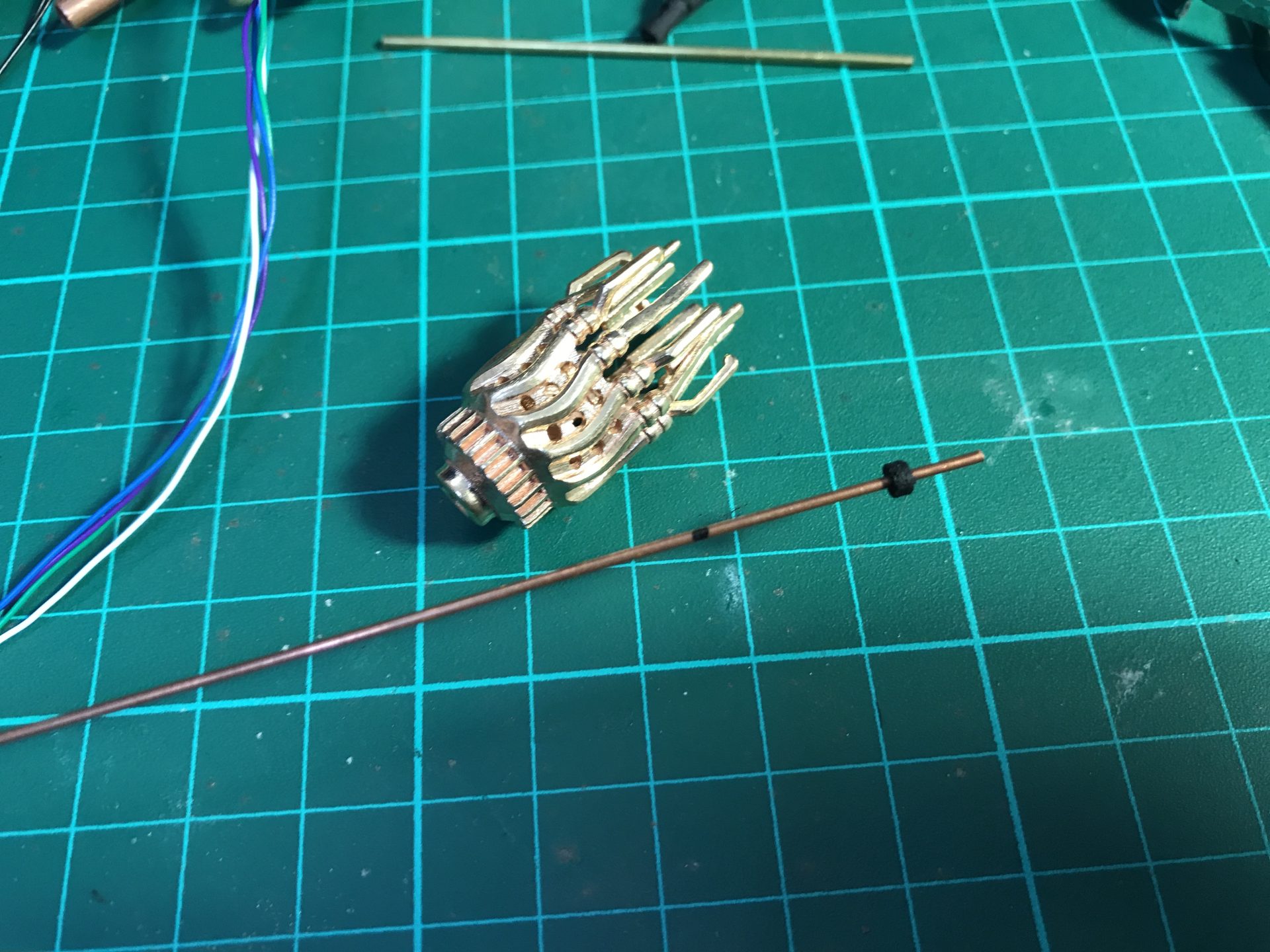
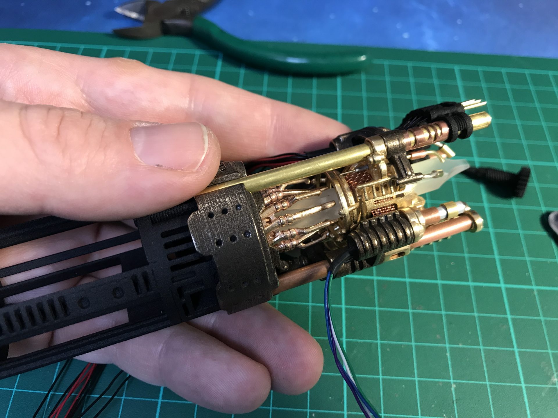
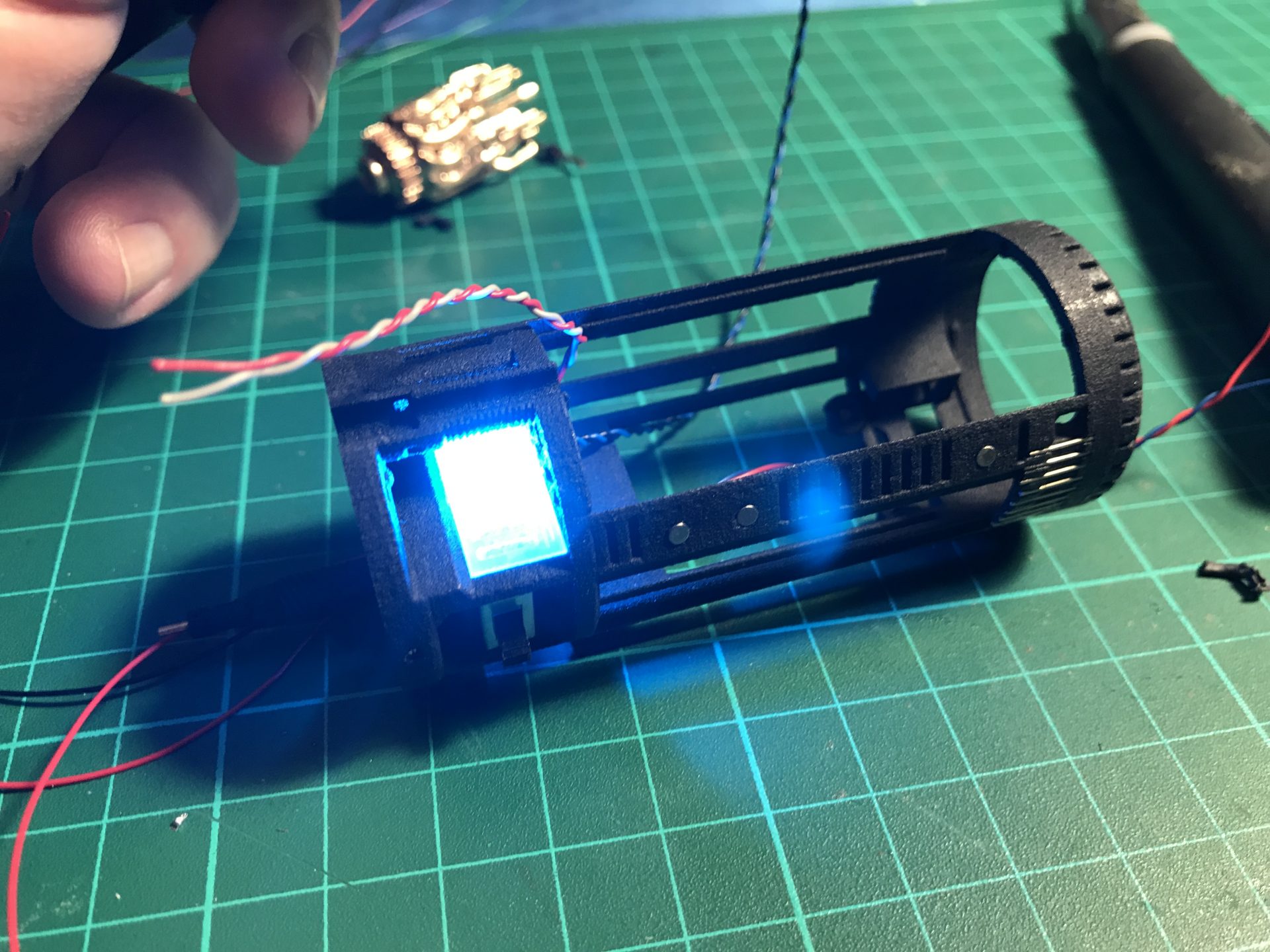
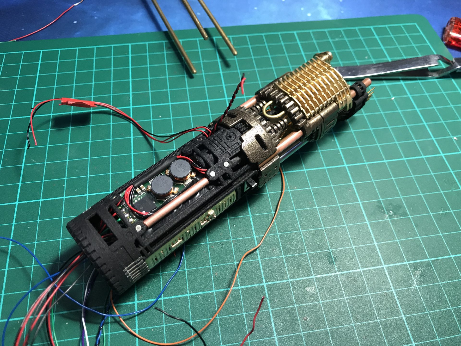
Step 12: Assemble the Arc Reactor parts (the top part needs to be cut out of the main part). If printed in steel, they can be polished for a better look. Use copper wires to build the Arc Reactor (electric wires for example as a good source). Once the wires attached and secured, insert the frosted plastic part (press fit normally). Then, glue the Arc Reactor into the front chassis part, there is a notch in the reactor part that aligns with the biggest hole of the front chassis part (the reasto.
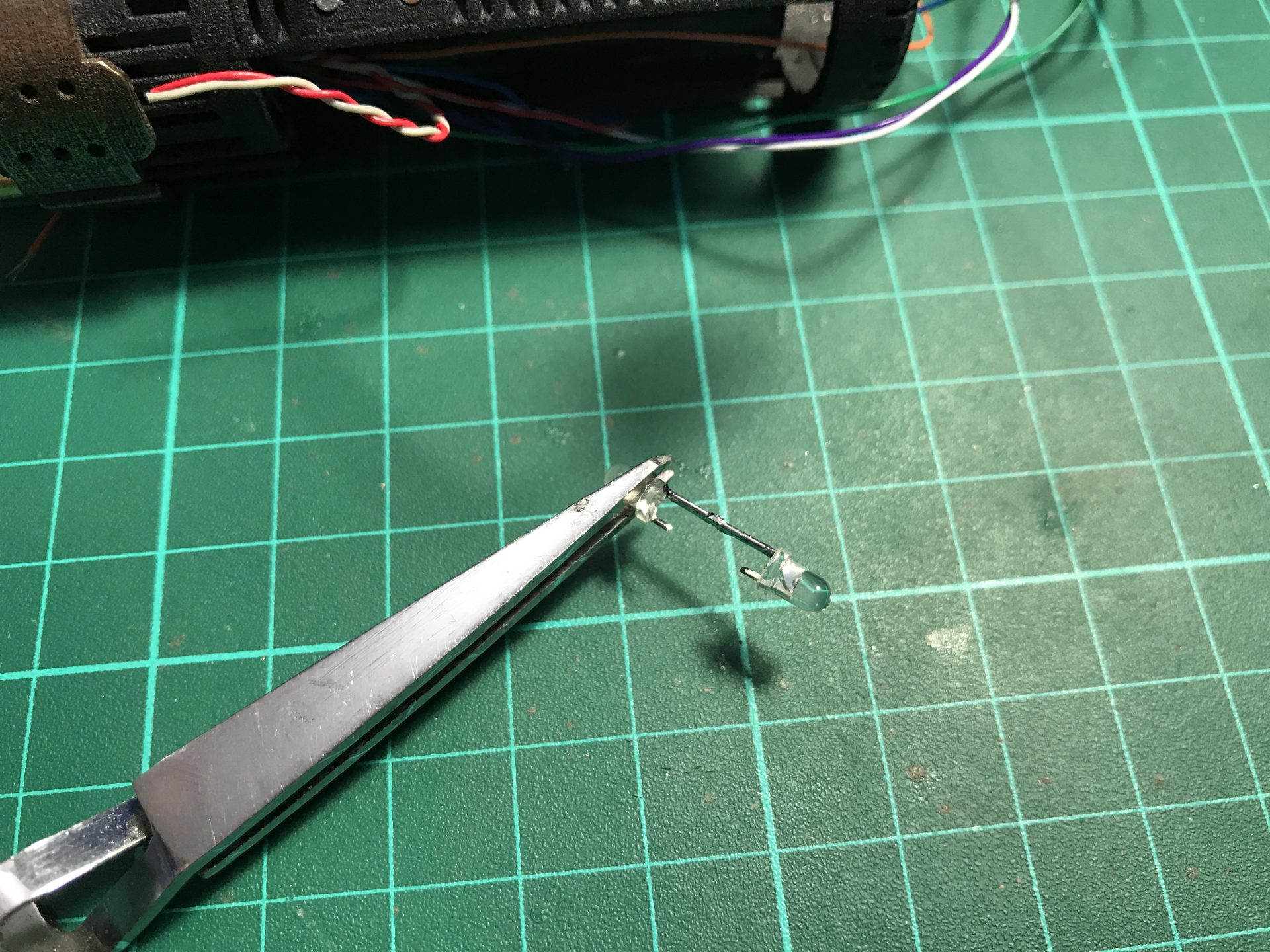
Note that the 5mm blue accent led needs to be sanded down to take less space.
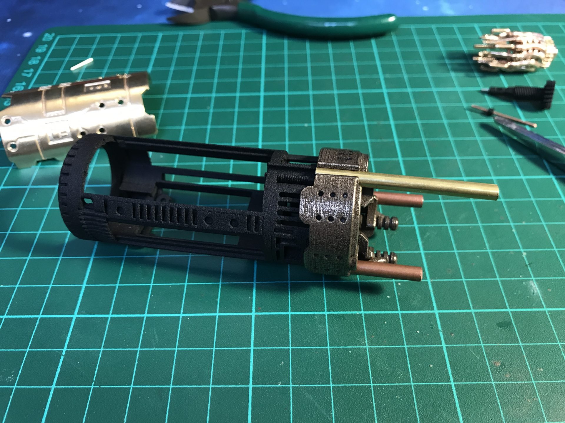
Step 13: You can install additional rods and tubes on the front chassis part (with a tiny drop of super glue to secure them). Fell free to shape them how you like. Here is an example:
Step 14: Cut the tubes to the length described in the section 2 (additional chassis parts). We strongly suggest to cut the tube with a slightly longer length, and then use of a caliper and hand file to reduce to the desired length. You can choose to Use brass, copper or aluminium as you prefer. You then have to secure them on the chassis parts with a bit of super glue using a spare 4-40 threaded rod as guide.
– Attach the three Tube 1) (4mmODx5mm) on the front chassis part:

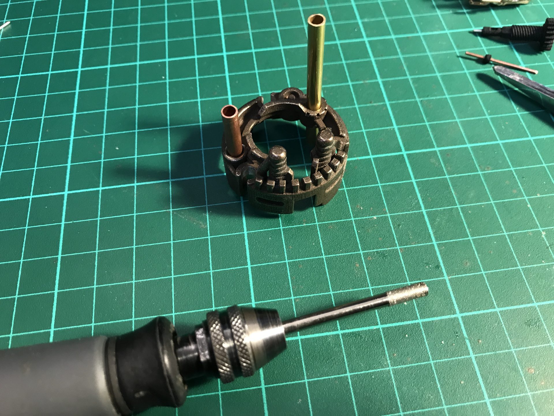
– Attach the the tube 2) and one of the tube 3) (4mmODx30mm) on the each side of the Part07 Crystal Chamber.
– Attach the two other Tube 3) (4mmODx30mm) on the Part06 (the holes might need to be cleared a bit to fit and be glued properly.
– The tube 4) (4mmODx26.6mm) will go later in the Part05 to complete the 3 tube in the front of the CC.
– You can add other rods like on the example below (and even make it a custom Tangible Font Selection connector).
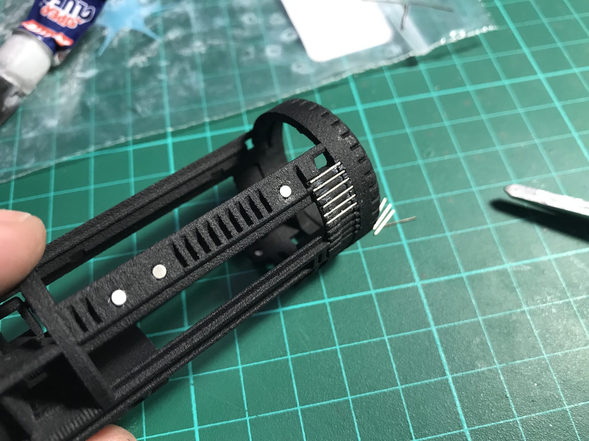
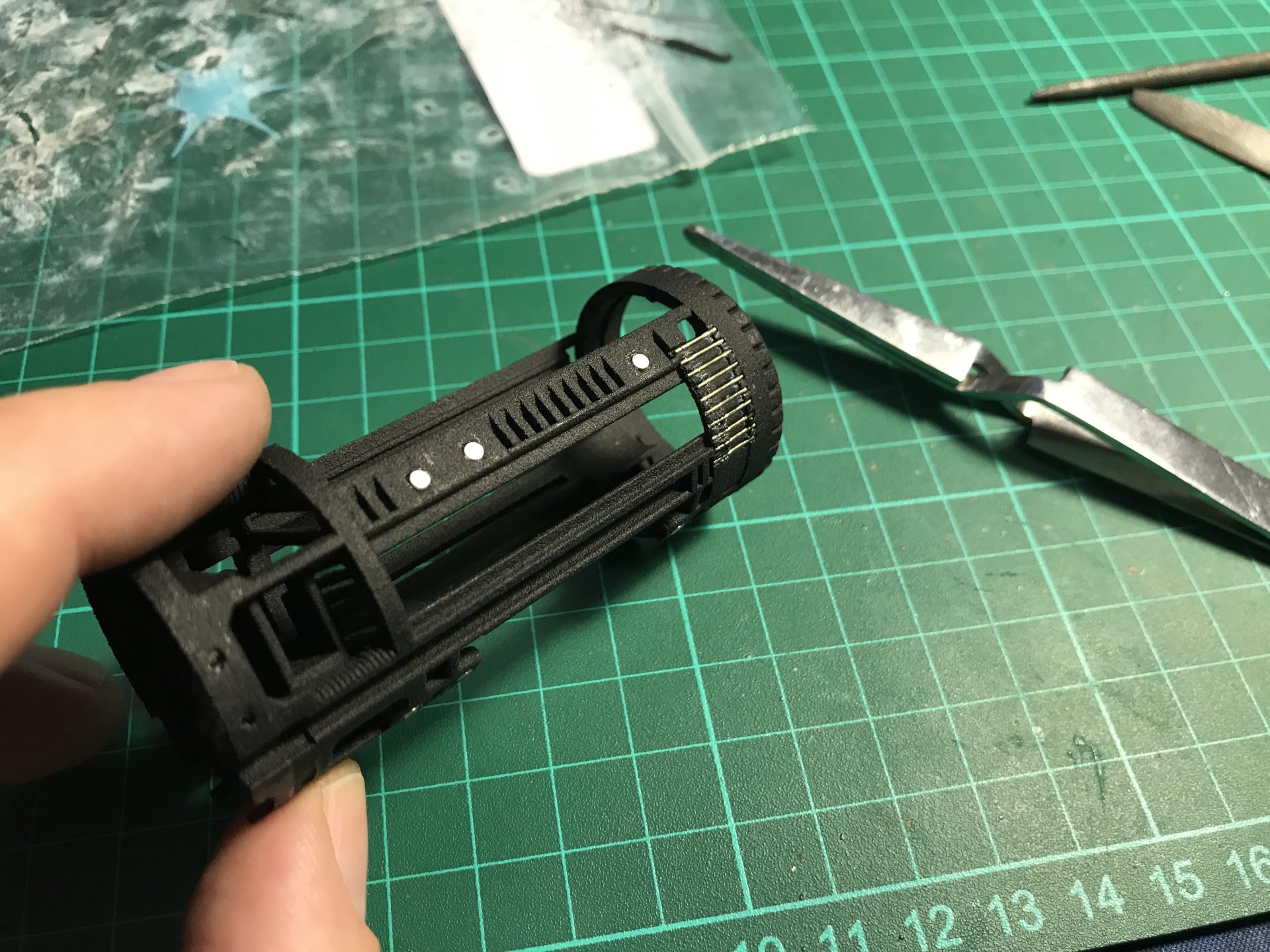
Step15: Glue the 3mmODx2mm magnets into both partx and partx.
/! important: make sure to respect the magnet polarity before gluing them!
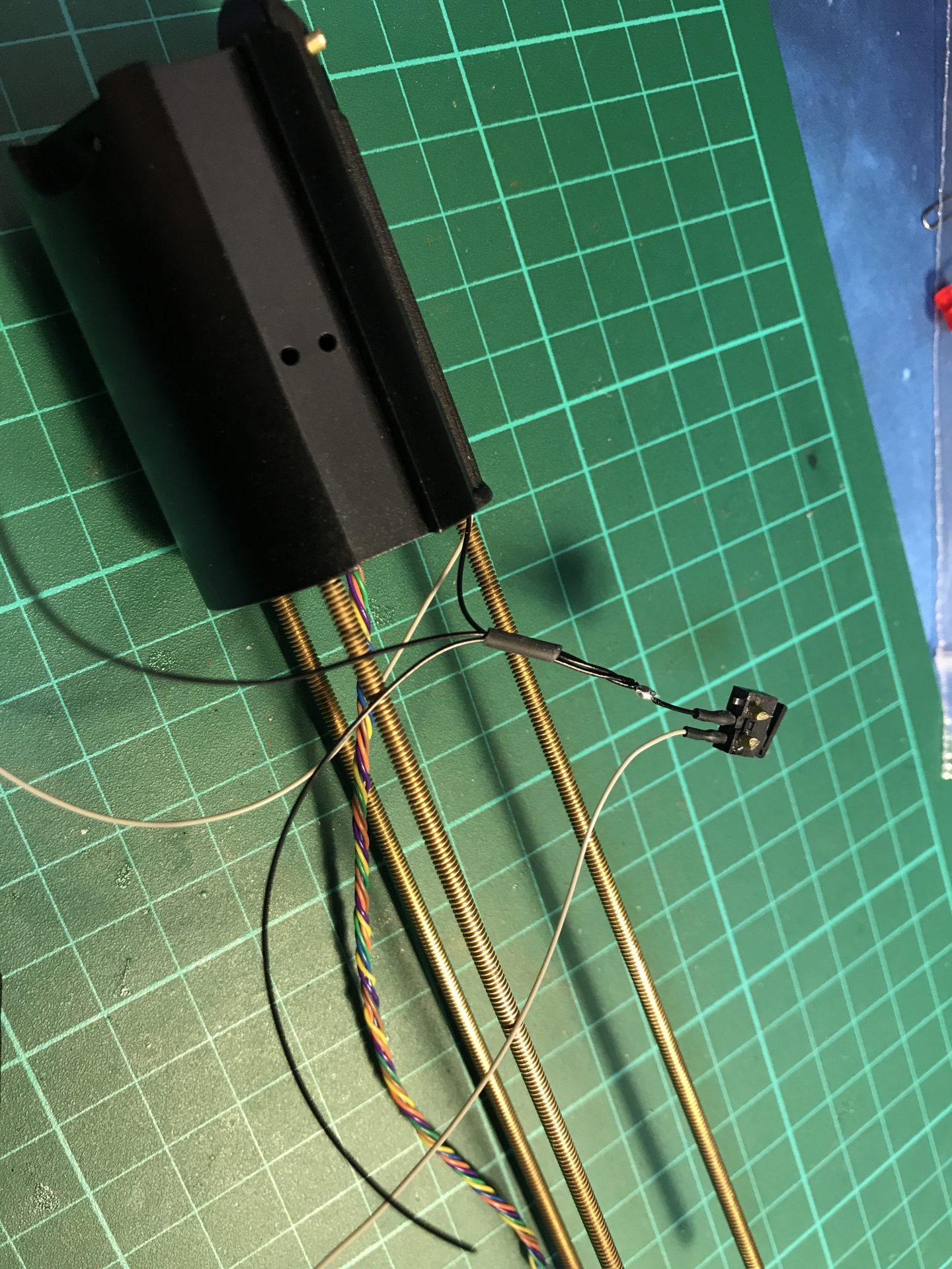
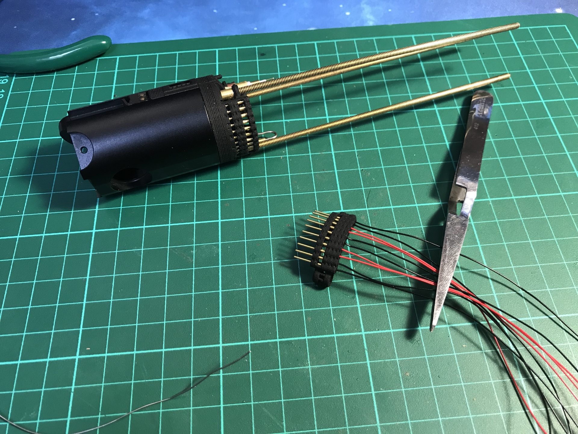
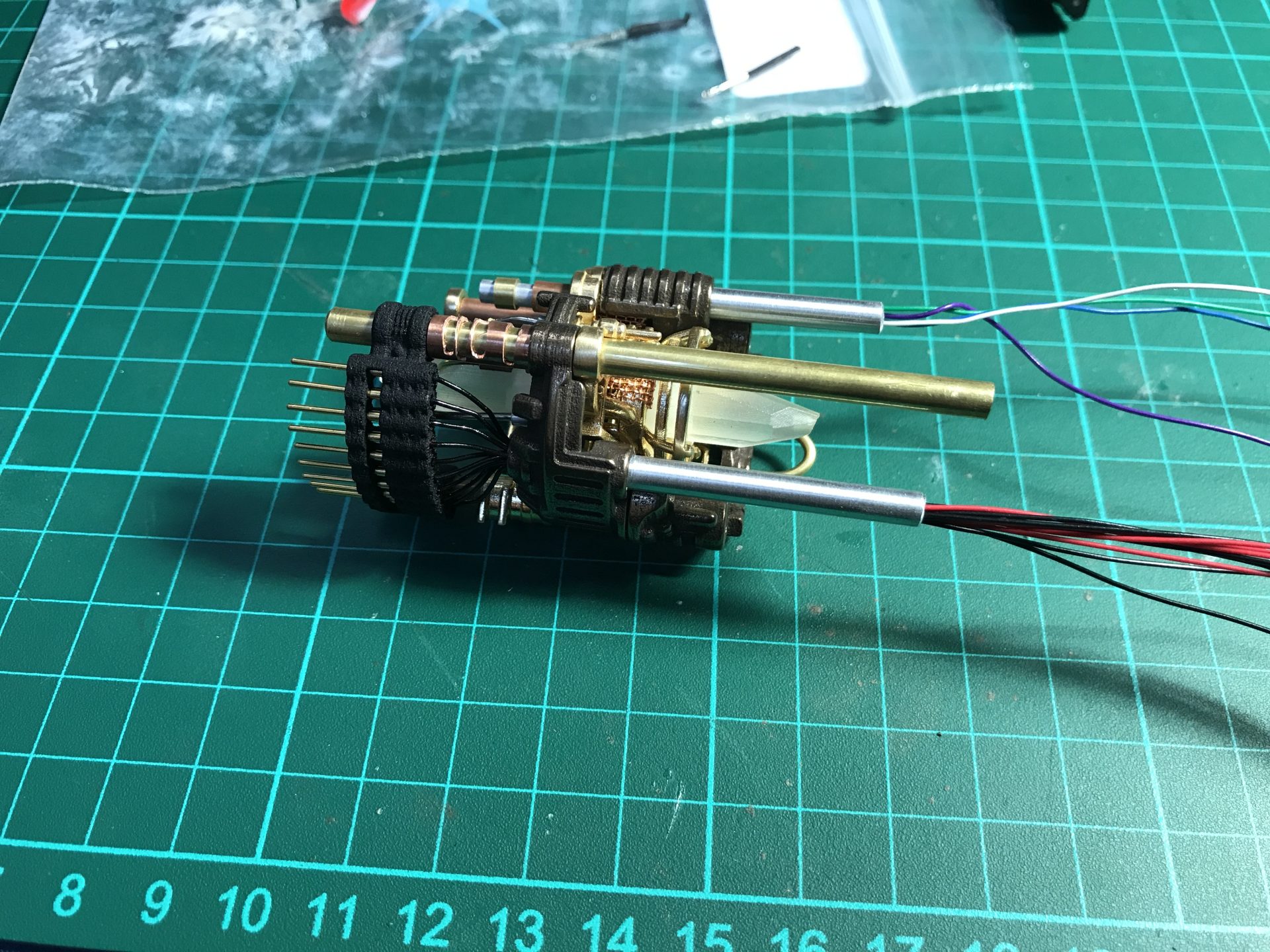
Step16: Install the female pins. Make good note of your wires positions, cut them to leave just enough margin, then solder the female pins. When soldering the pins, make sure to leave no except of pewter on the pins, as it will prevent them to be inserted currently into the holder. We used super glue (tiny drops) to secure the pins in the holder.
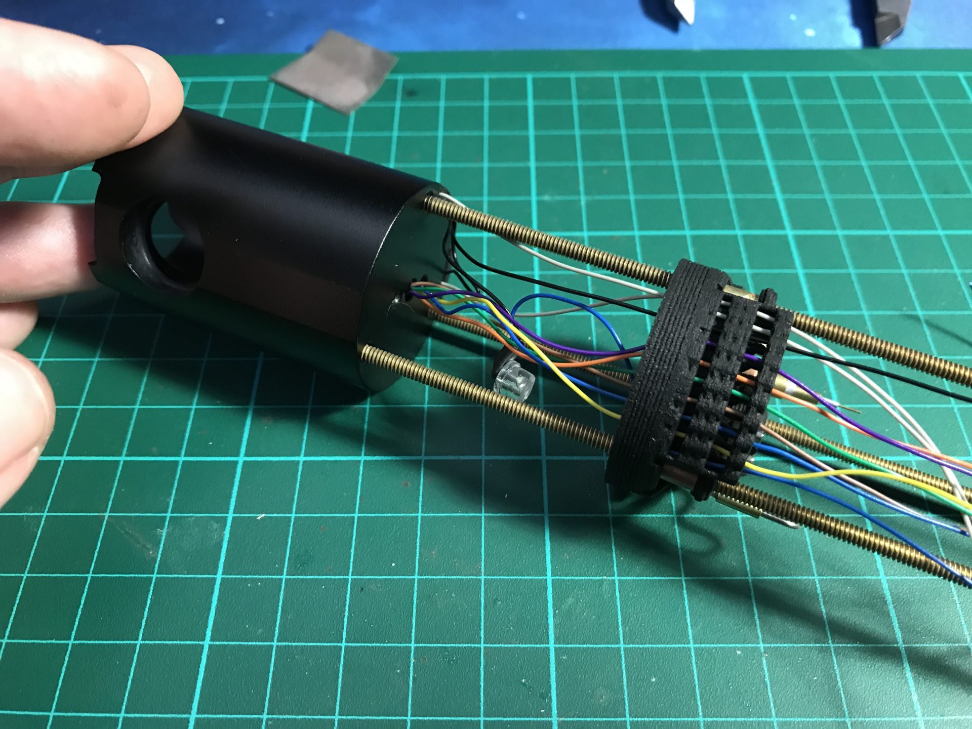
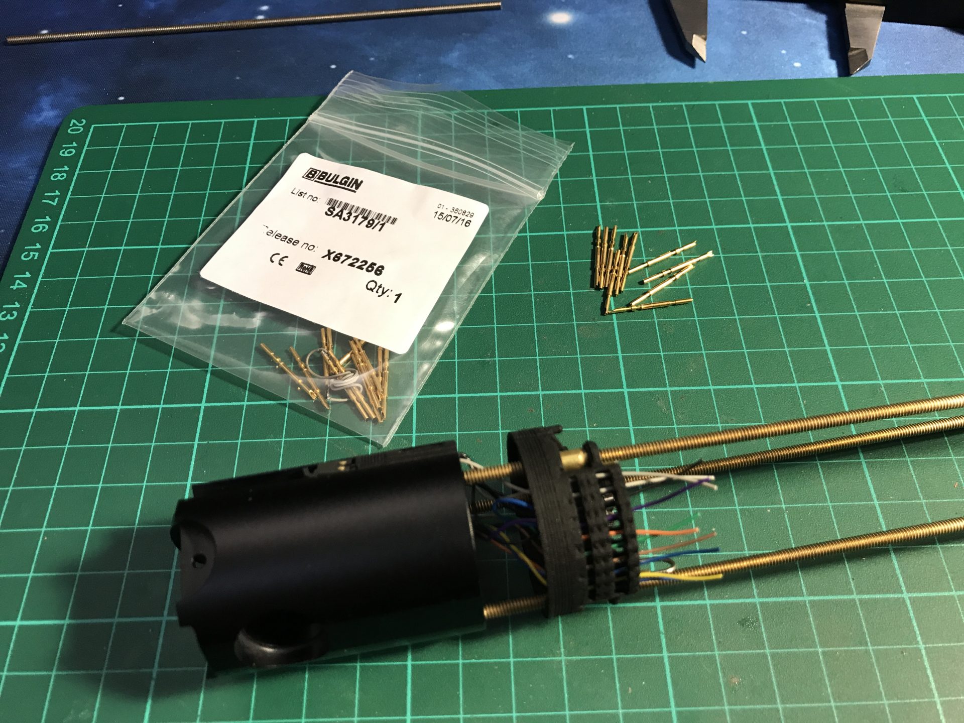
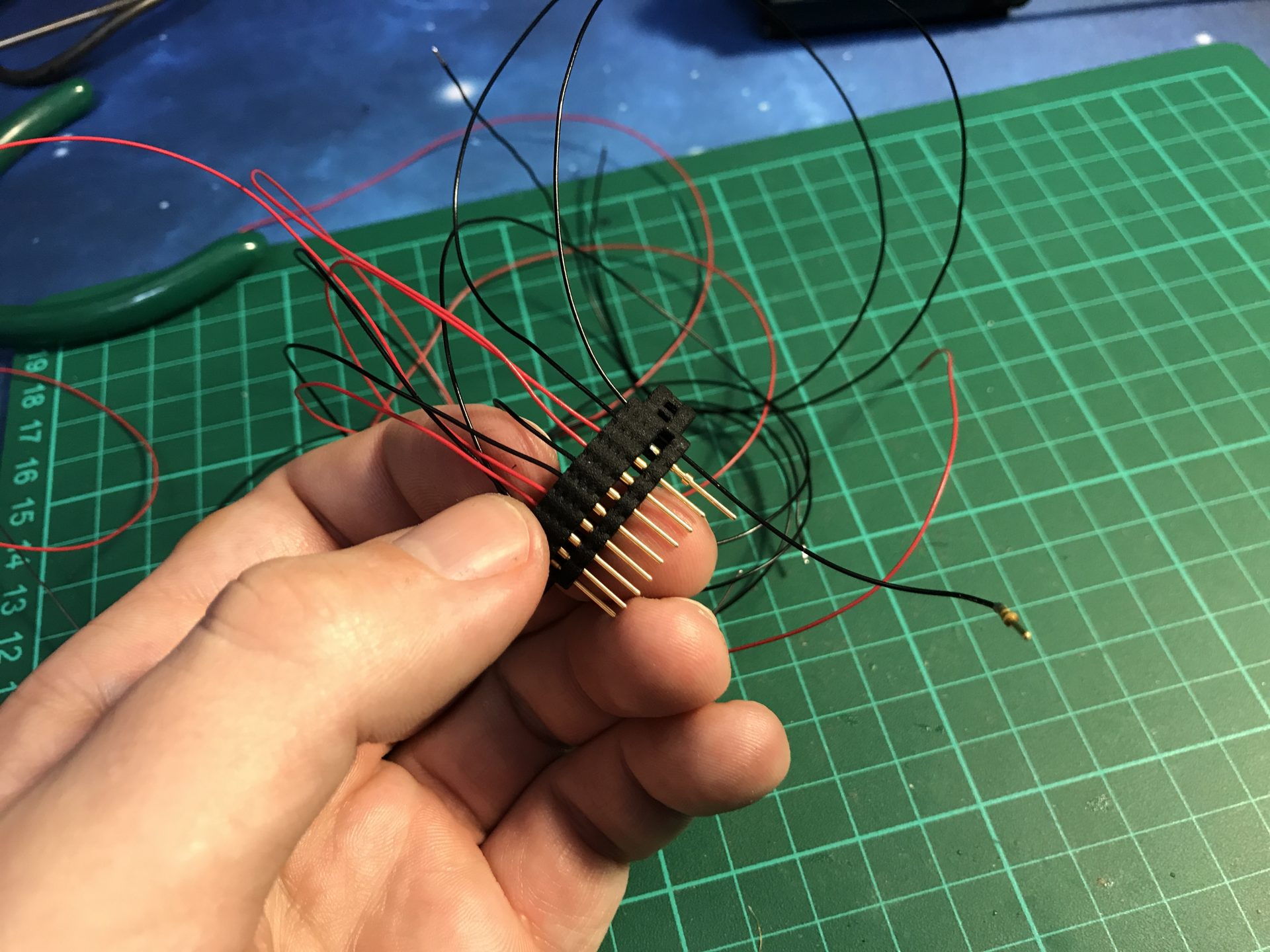
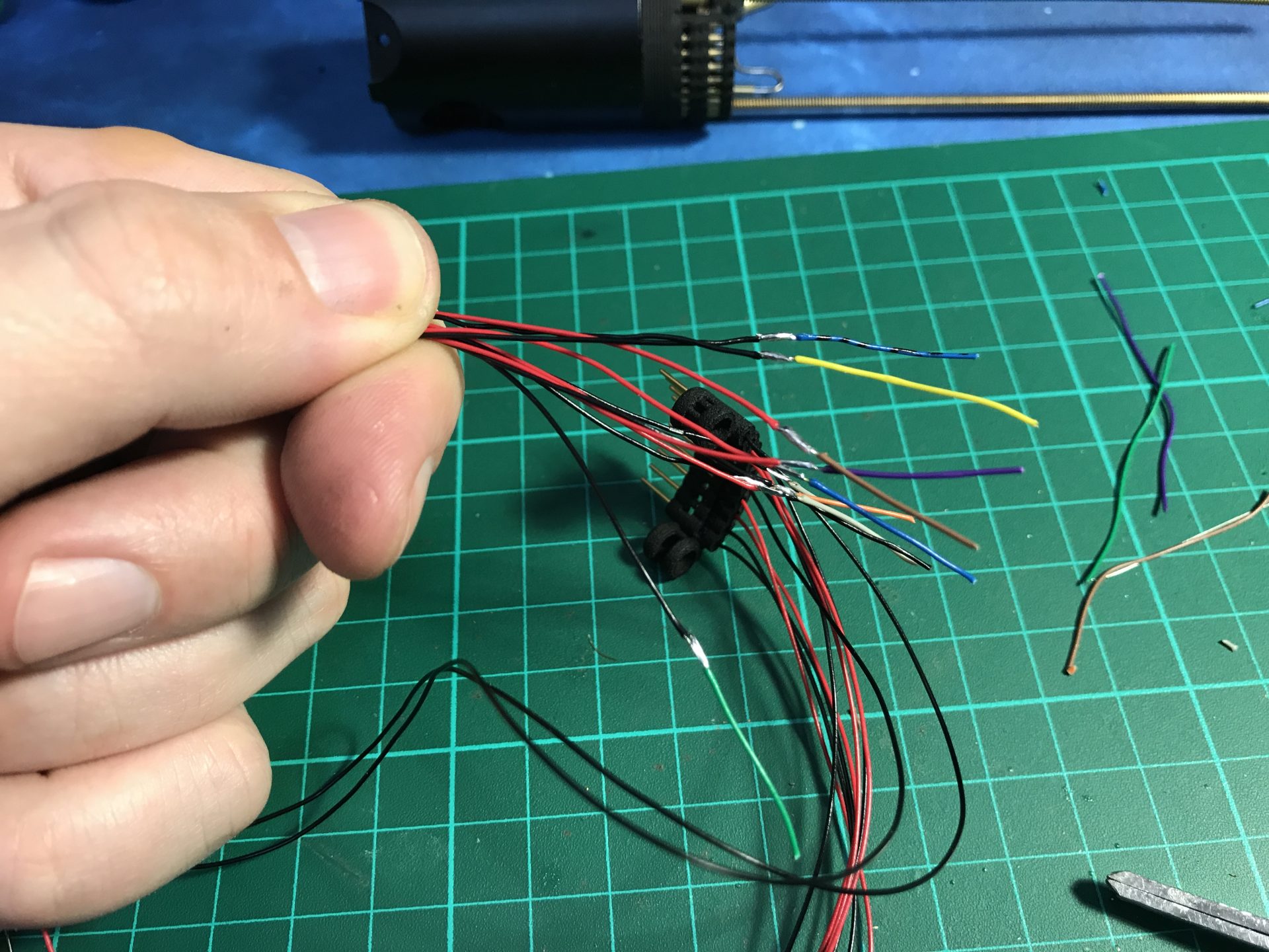
Step 17: Solder the male pins (same advice, to not exceed on the amount of pewter). We used super glue again to secure the male pins in the dedicated holder. The wires being exposed, choose the color of wires you prefer. You can then identify the wires at the end by using a small length of colored wire. Once the custom male plug is done, you can insert it on the chassis rods
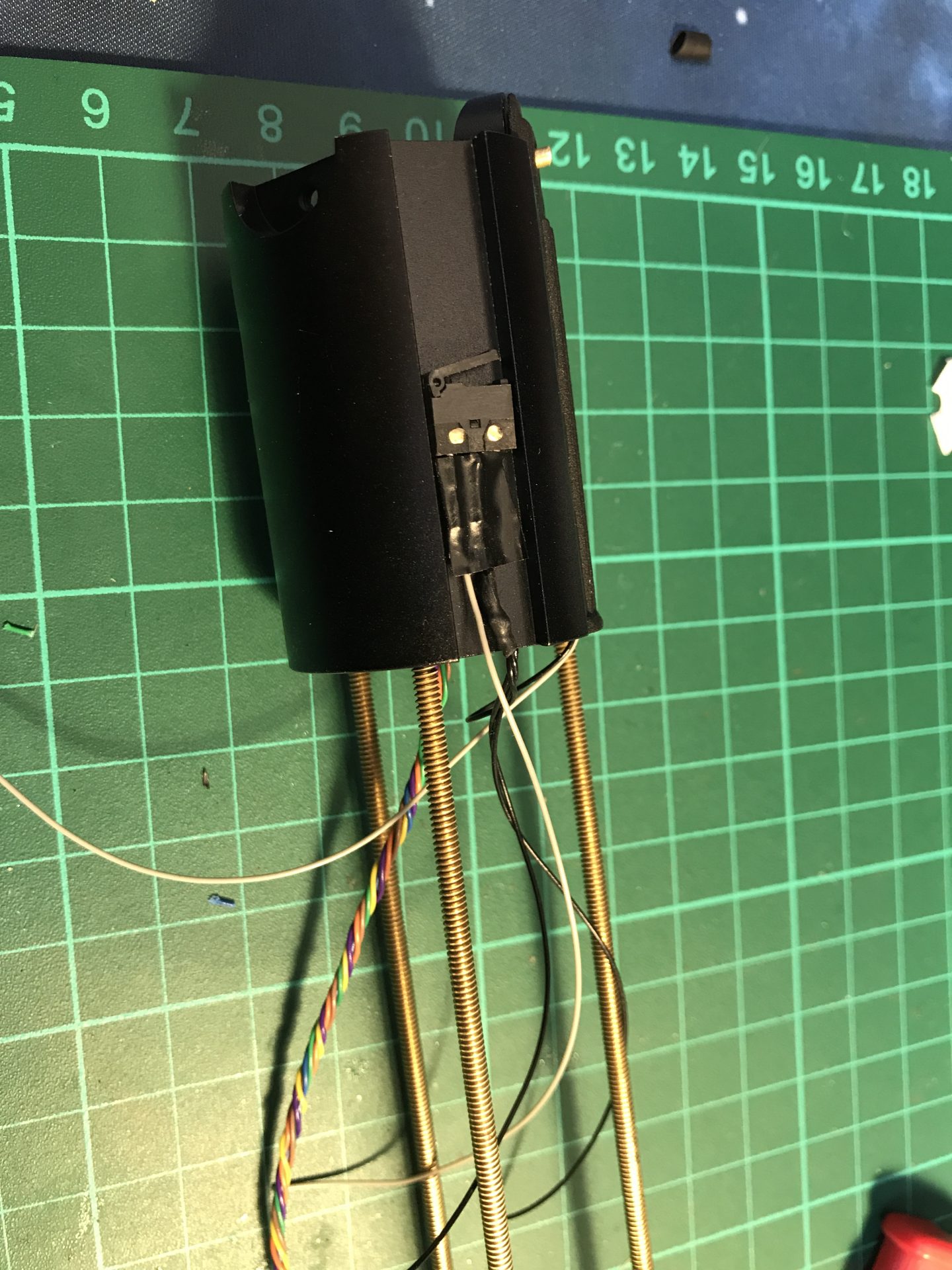
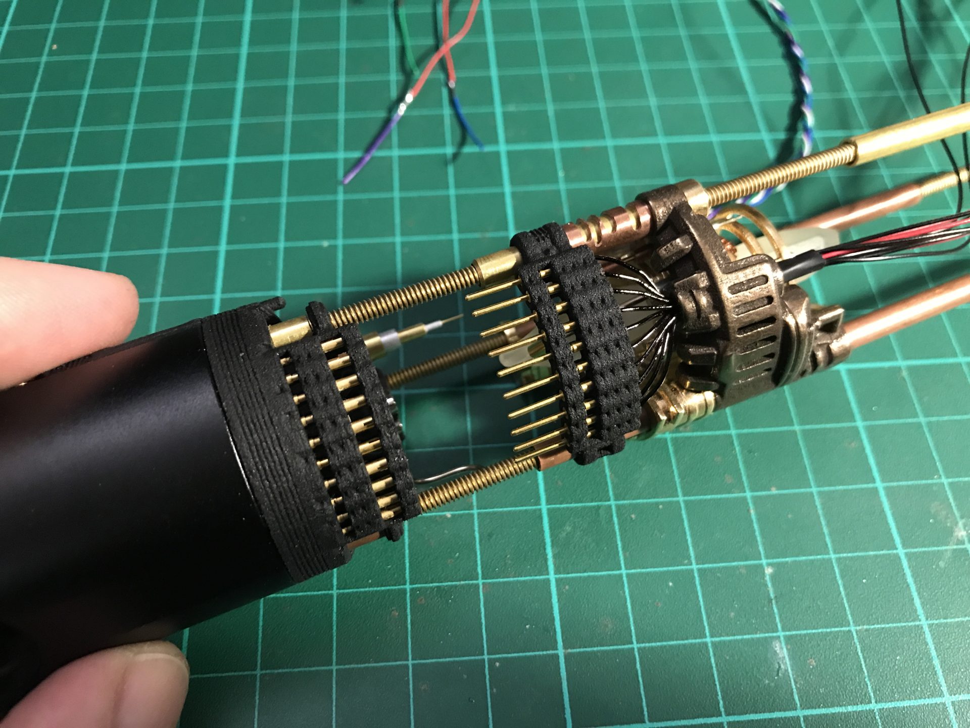
Step 18: Testing time! Add the Tube 8) (5mmODx12.7mm) over the tube 4) in order to support the custom pins male connector. Then add the custom connector by sliding it over the tubes 4) and 2) and check if the assembly work properly. Once everything testing, you can remove the male connector and proceed to the next step.
/! Important: It is very important at that point to check the connectivity of each of your 10 pins (Switches, Main Led and Accent Led). It is also very important to make sure both upper and bottom parts of the chassis magnets bind properly. If there is any gaps, adjust your tubes accordingly or the male connector placement accordingly. For example, if your male connector sits too high, it will create a gap between the magnets, reduce the length of the support Tube 8) to insert the connector a bit lower.
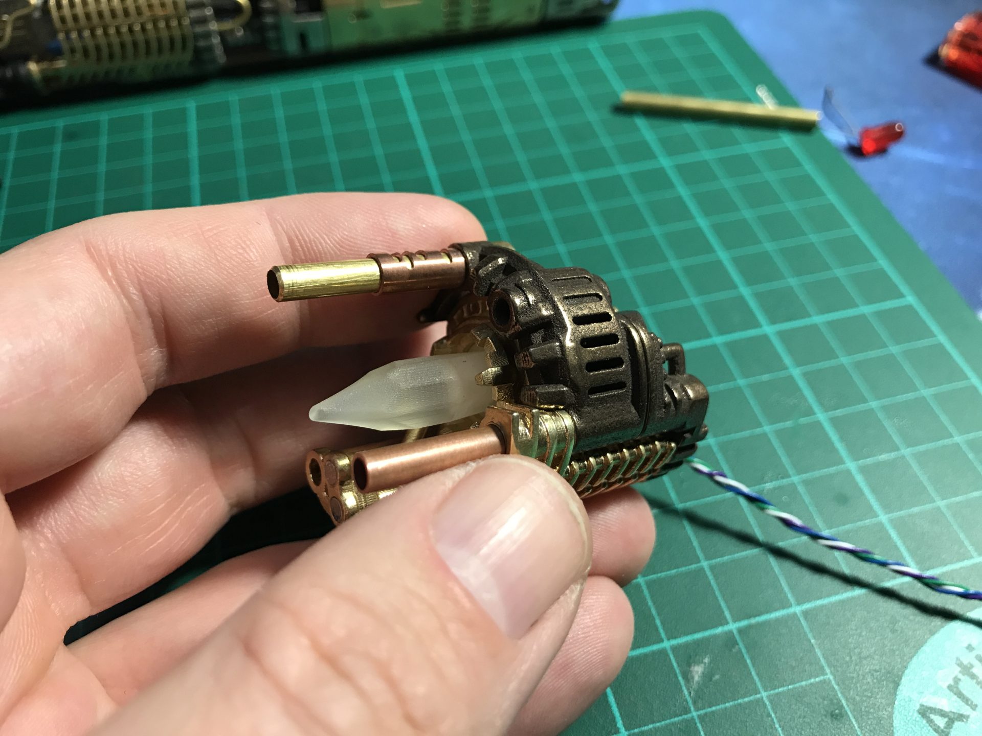
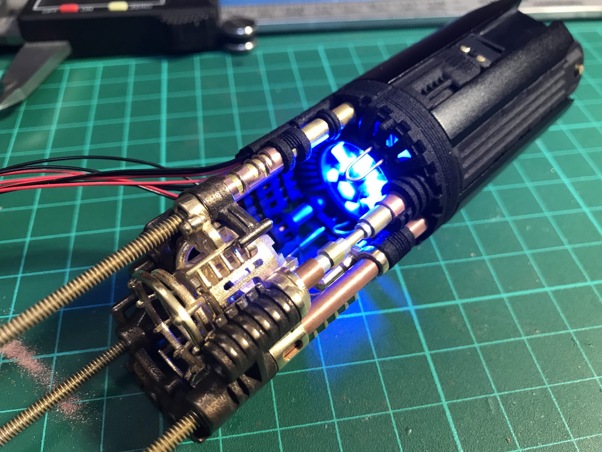
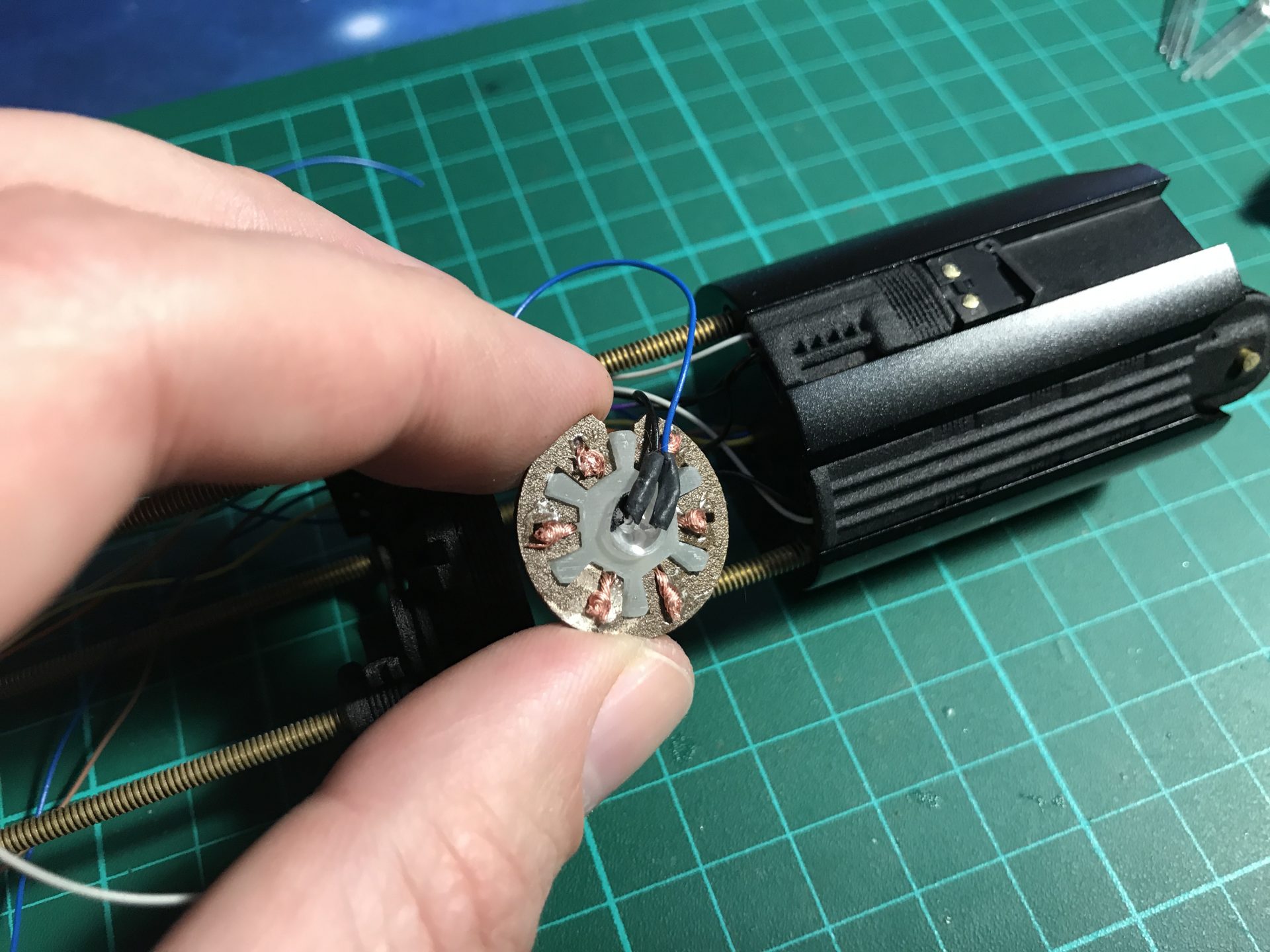
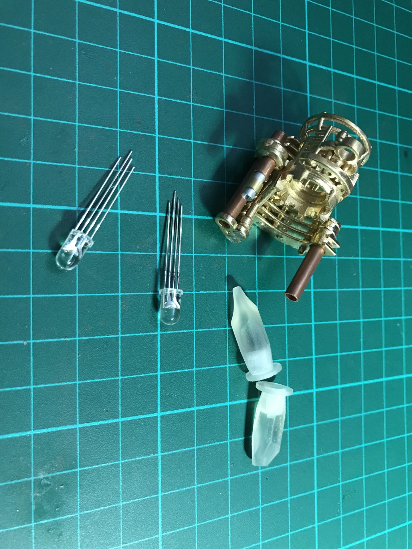
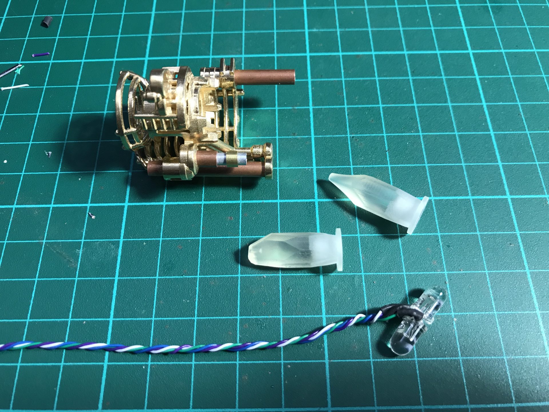
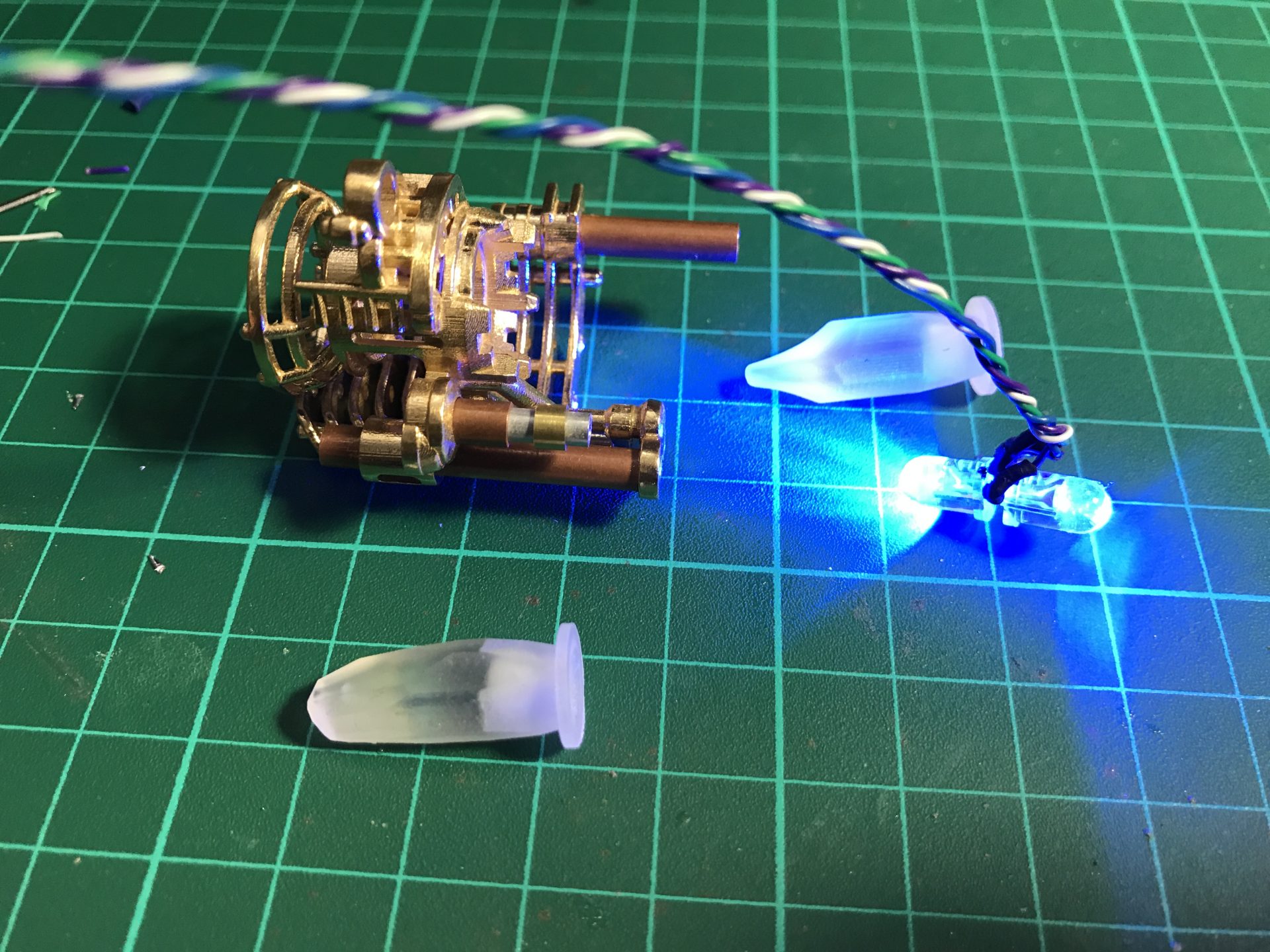
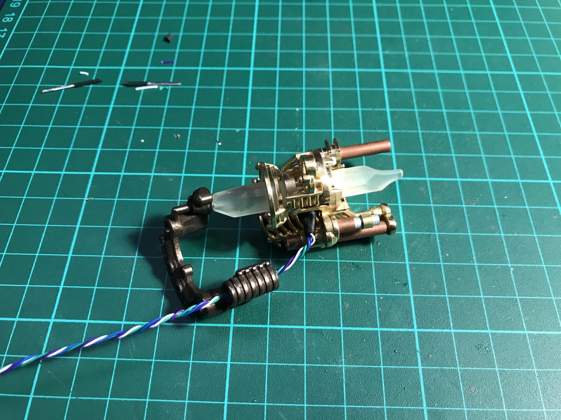
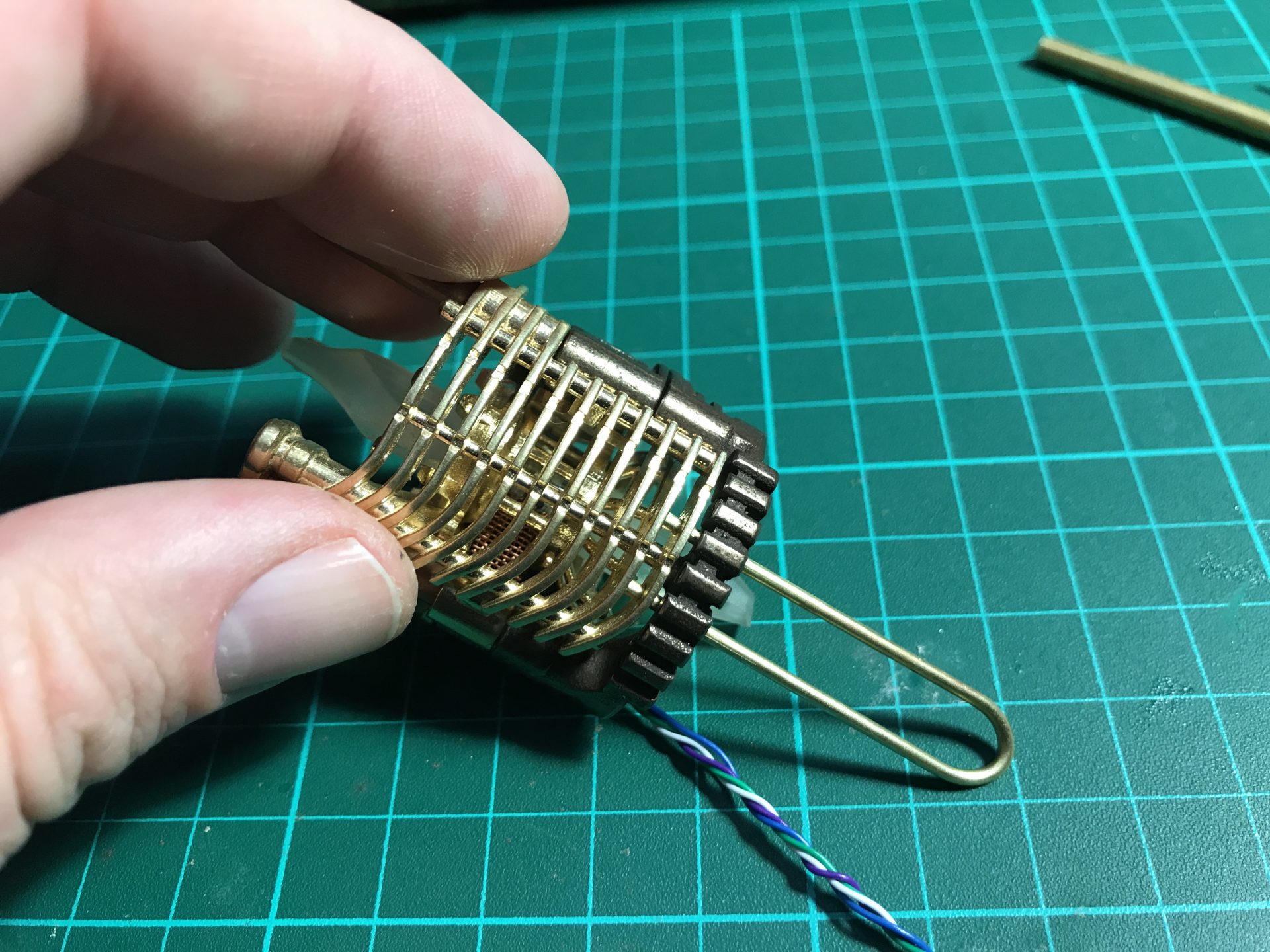
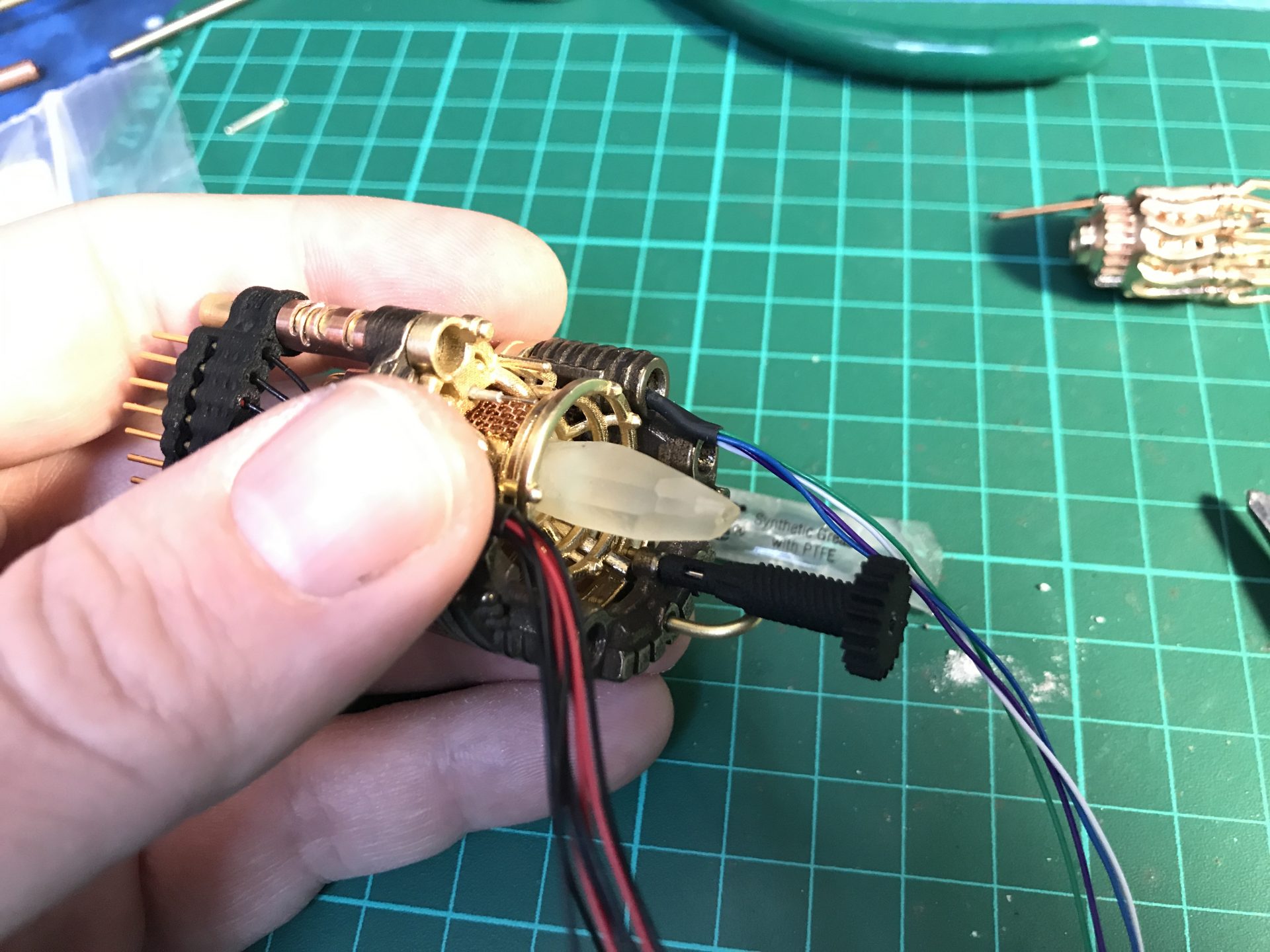
Step 19: To install the Crystal Chamber leds, we join together and solder two 5mm RGB back to back. The led assembly can only be inserted in the chamber from one side (make sure you limit the led leads to the minimum). The wires exist from the side of the CC as shown in the pictures below. Then add and glue your crystals (after testing the leds work fine of course).
Notes: Using the 3D printed crystal makes the assembly easier but Quartz can also be used; in that case, it is strongly recommended to drill a 5mm bore in the stone to welcome the leds and make the assembly stronger once glued together. Note that there is also a 1.25mmOD hole in the focusing crystal front, in order to support one of the rods 4) as part of the rotation devise assembly.
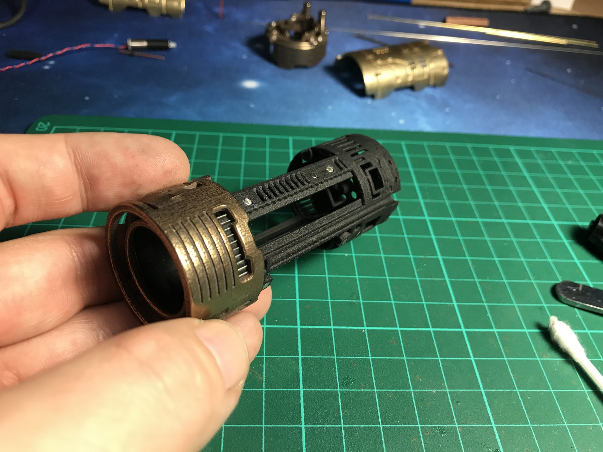
Step 20: Once the crystal installed, pass the wires into the part06 dedicated channel and slide the part. We recommend to glue Part05 and Part06 together with epoxy at this point, using rods for proper guidance.
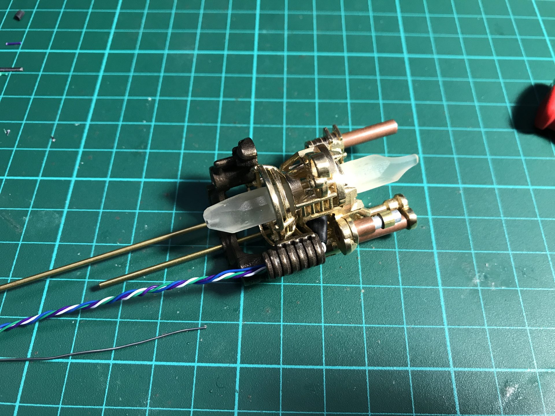
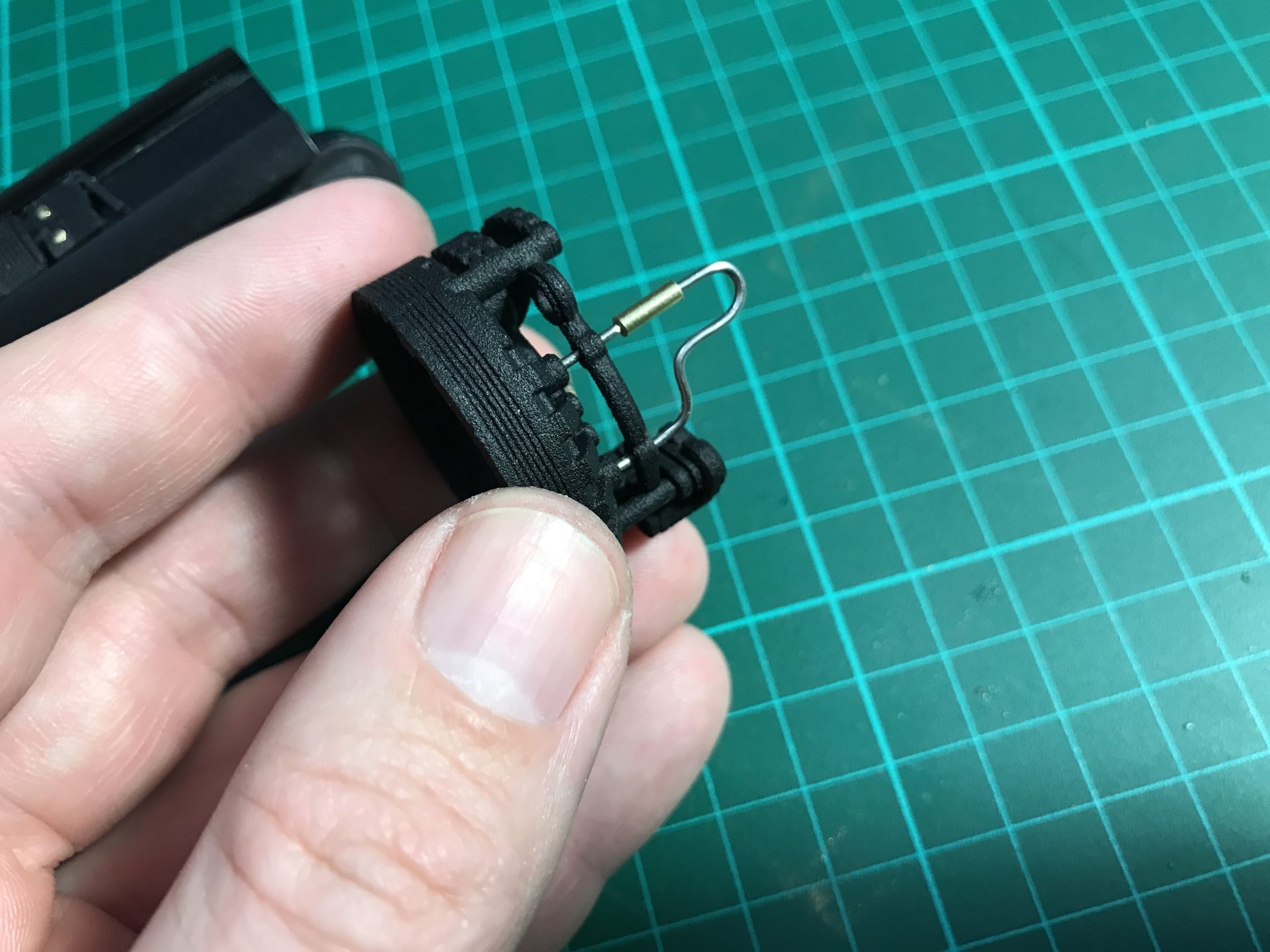
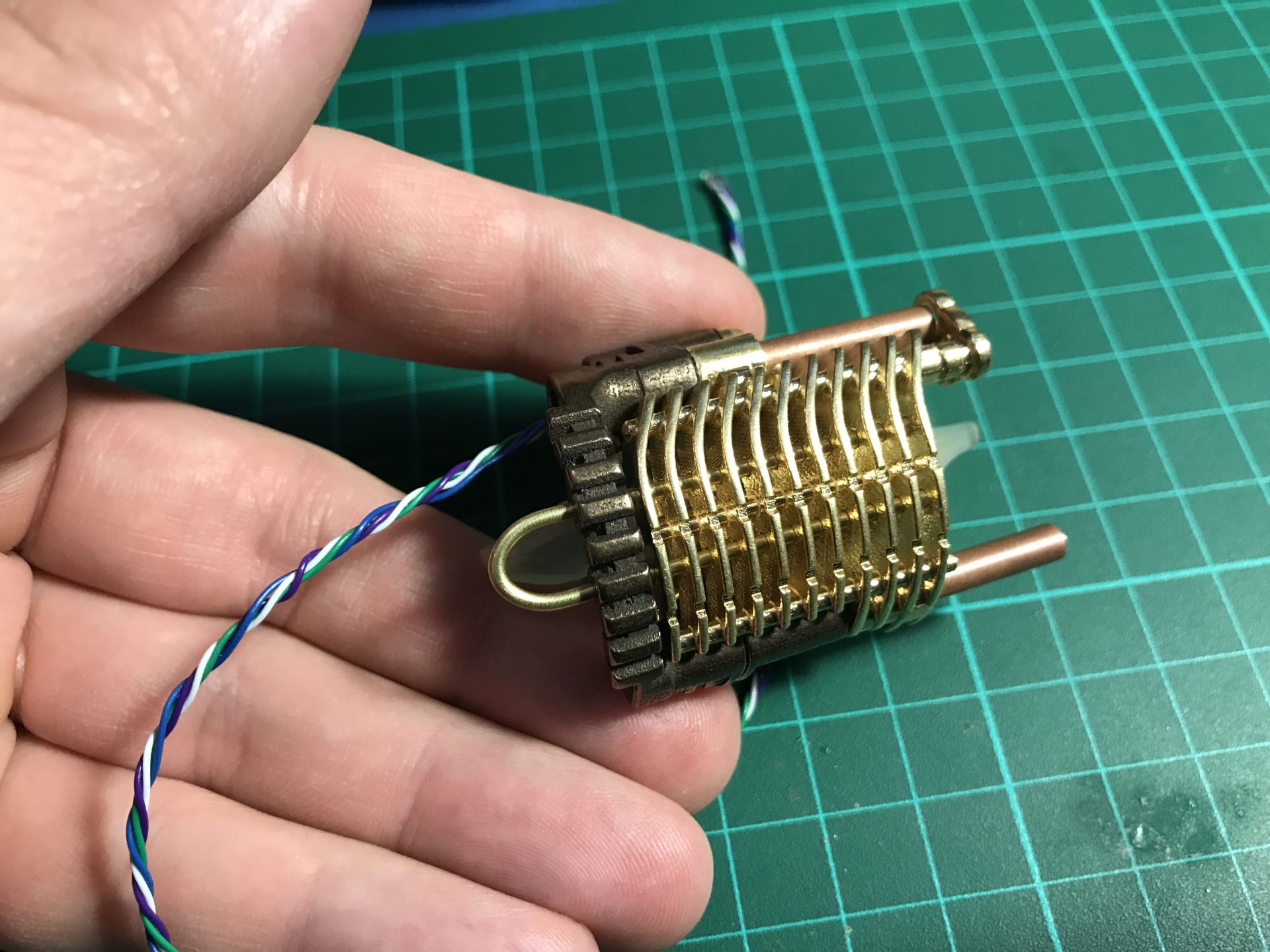
Step 21: As shown in the pictures below, add the Rod 3) (1.5mmOD U Shape) to complete the Crystal Chamber assembly (add a bit of super glue at the end of each rods to secure them).
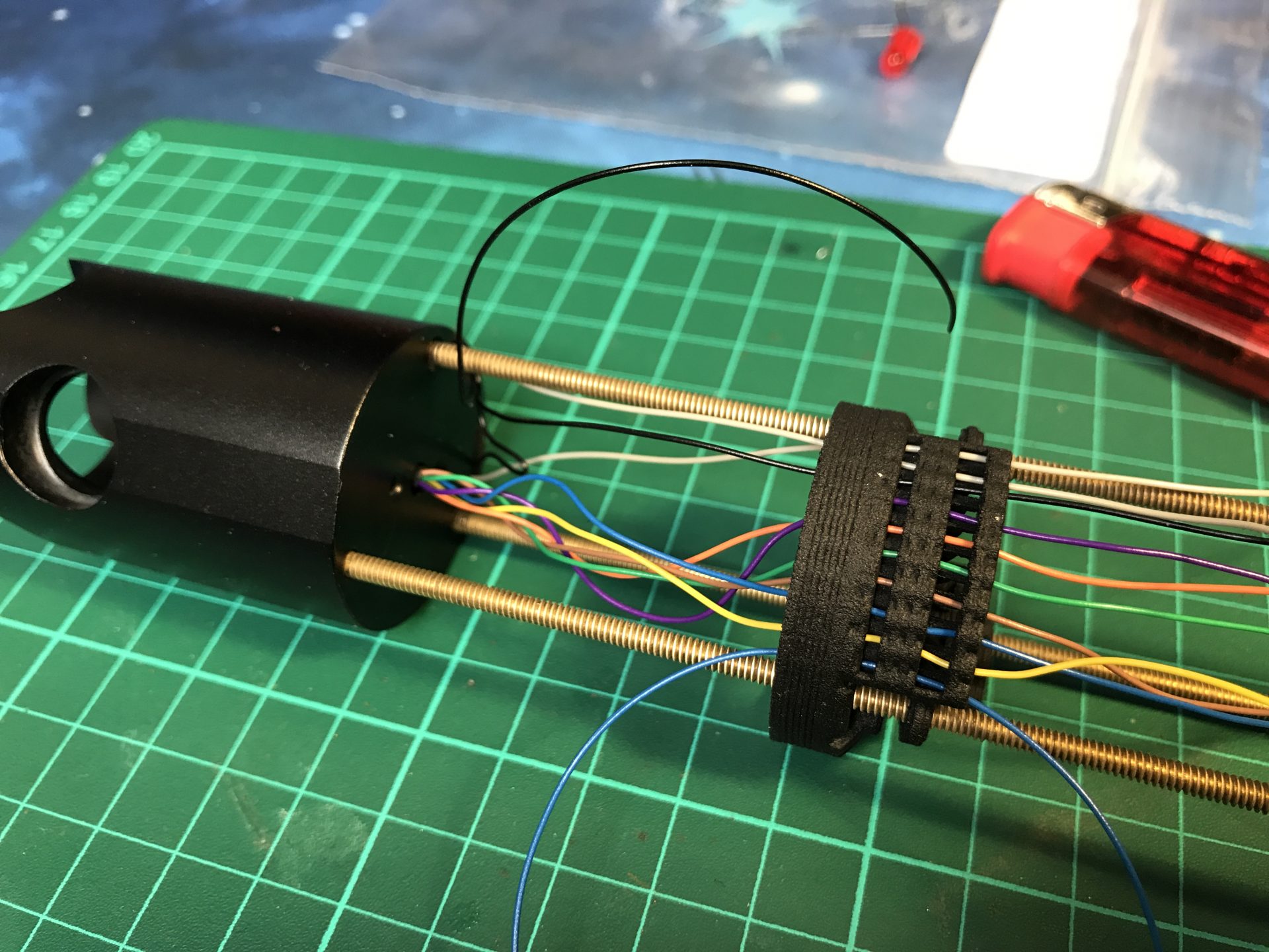
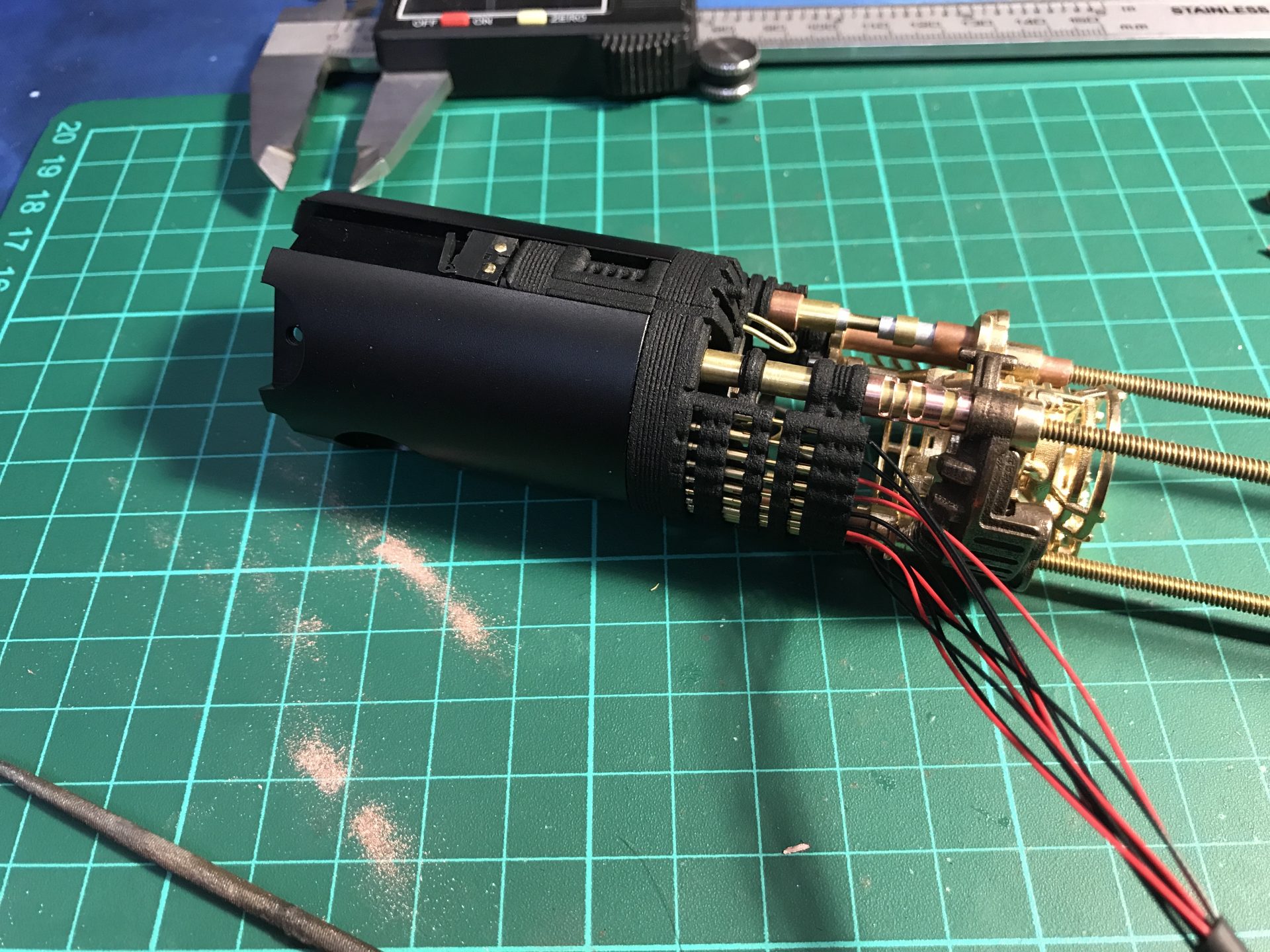
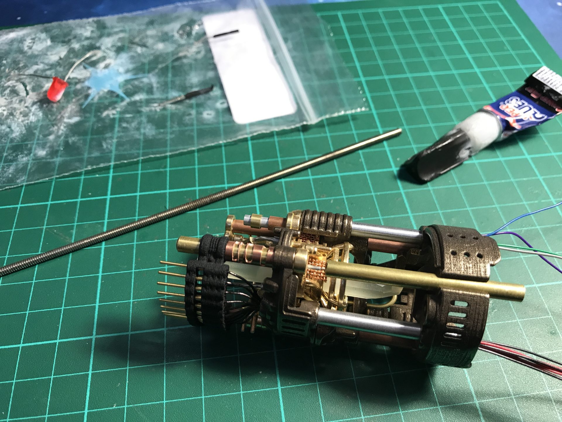
Step 22: Now time to install and secure the connector. Pass the 10 wires into the dedicated channel, and slowly pull them to eventually slide the male connector back onto the tubes, and to glue it with a bit of super glue.
we recommend having some heatshrink tube on the wires to ease their placement. You can shape your exposed wires better as shown below. At this point, it is recommended to test everything again.

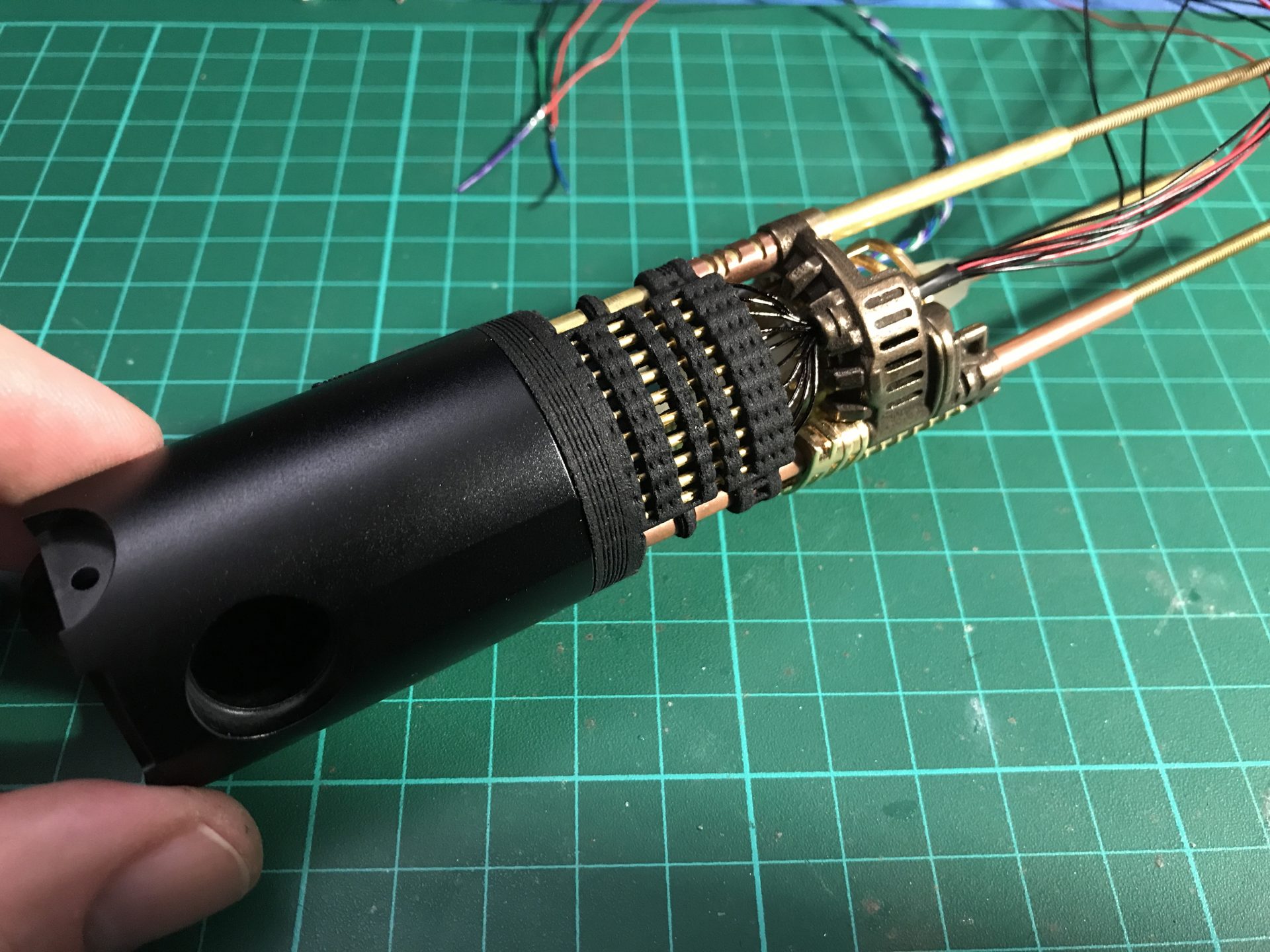
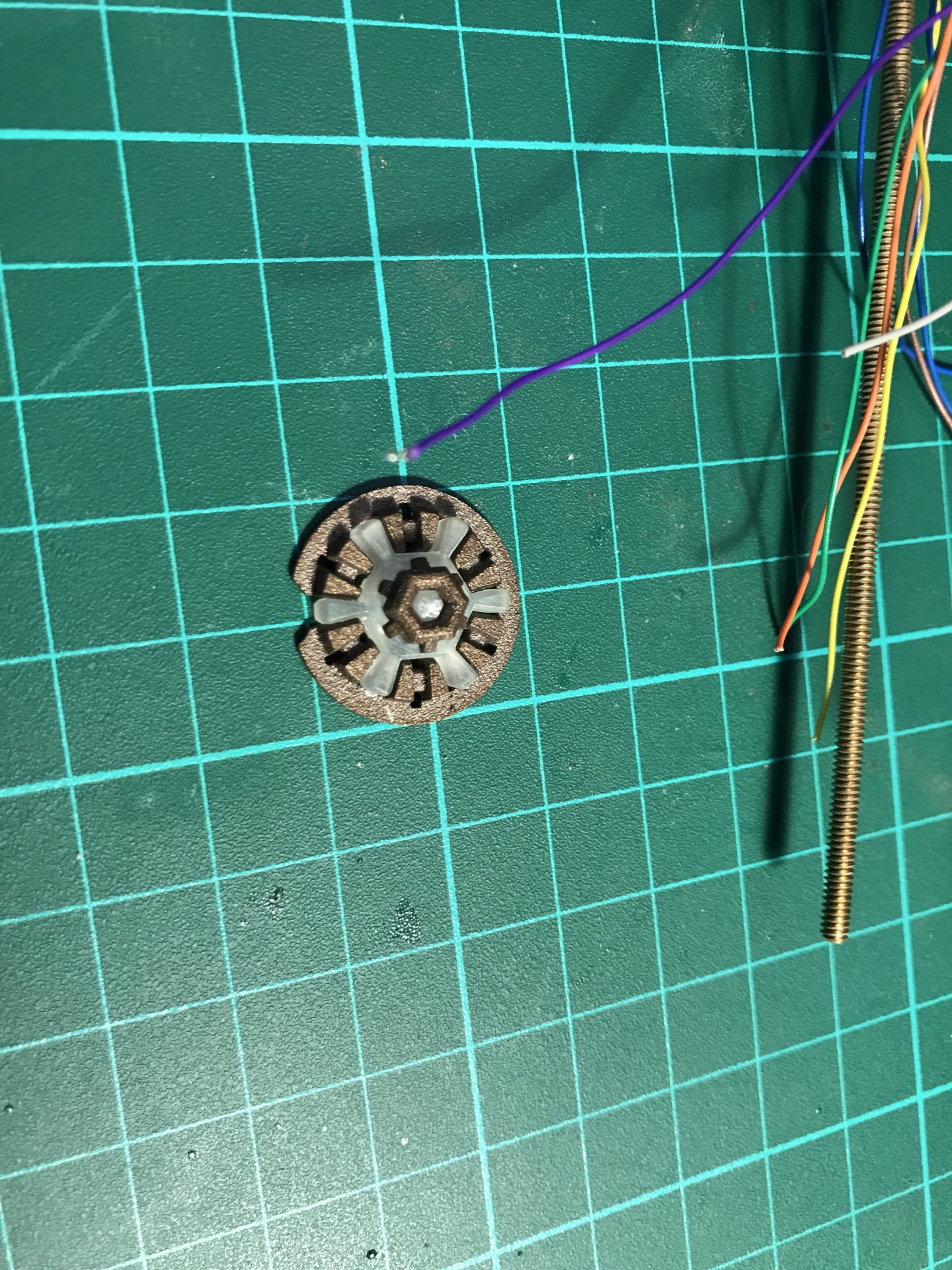
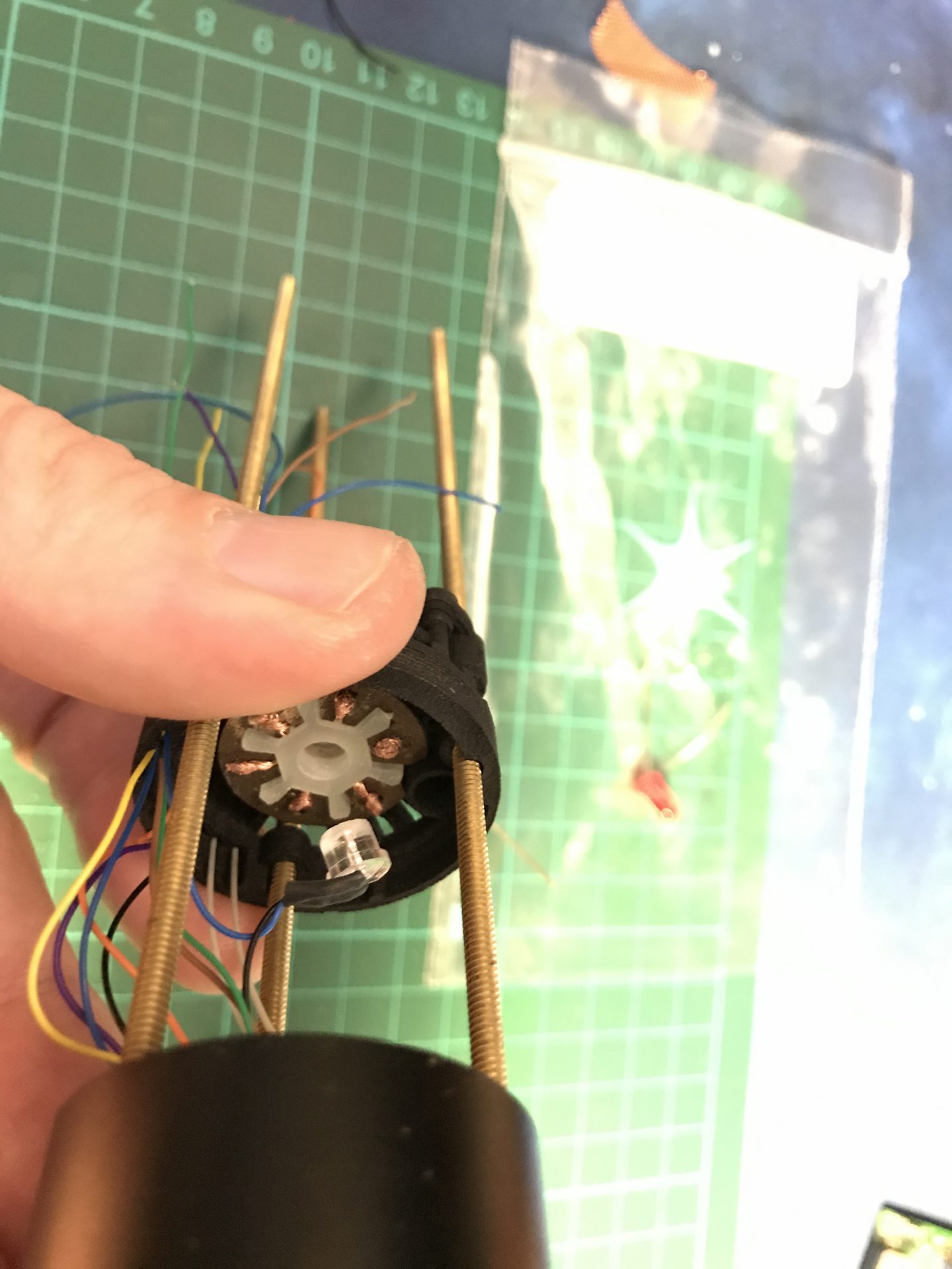
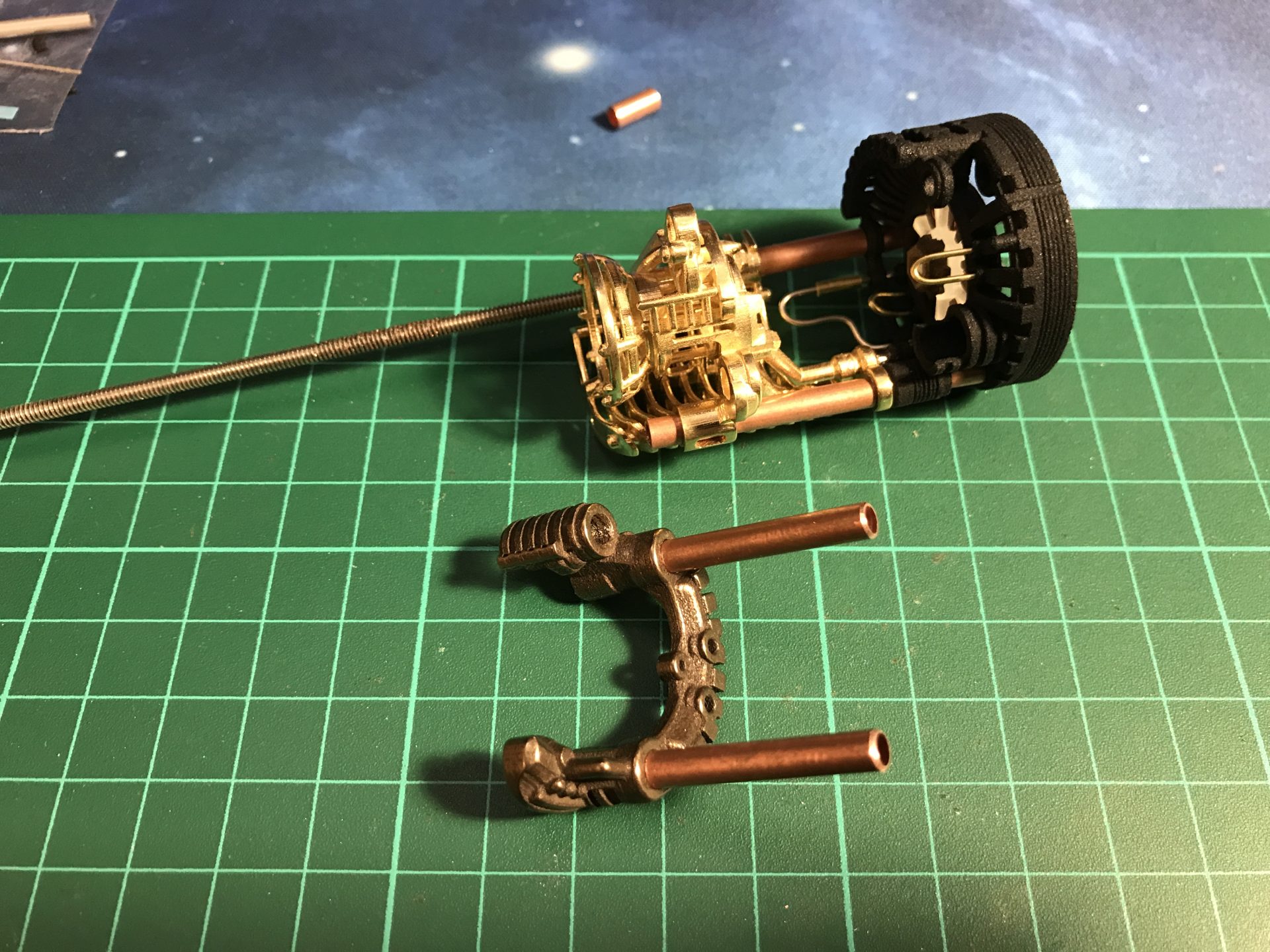
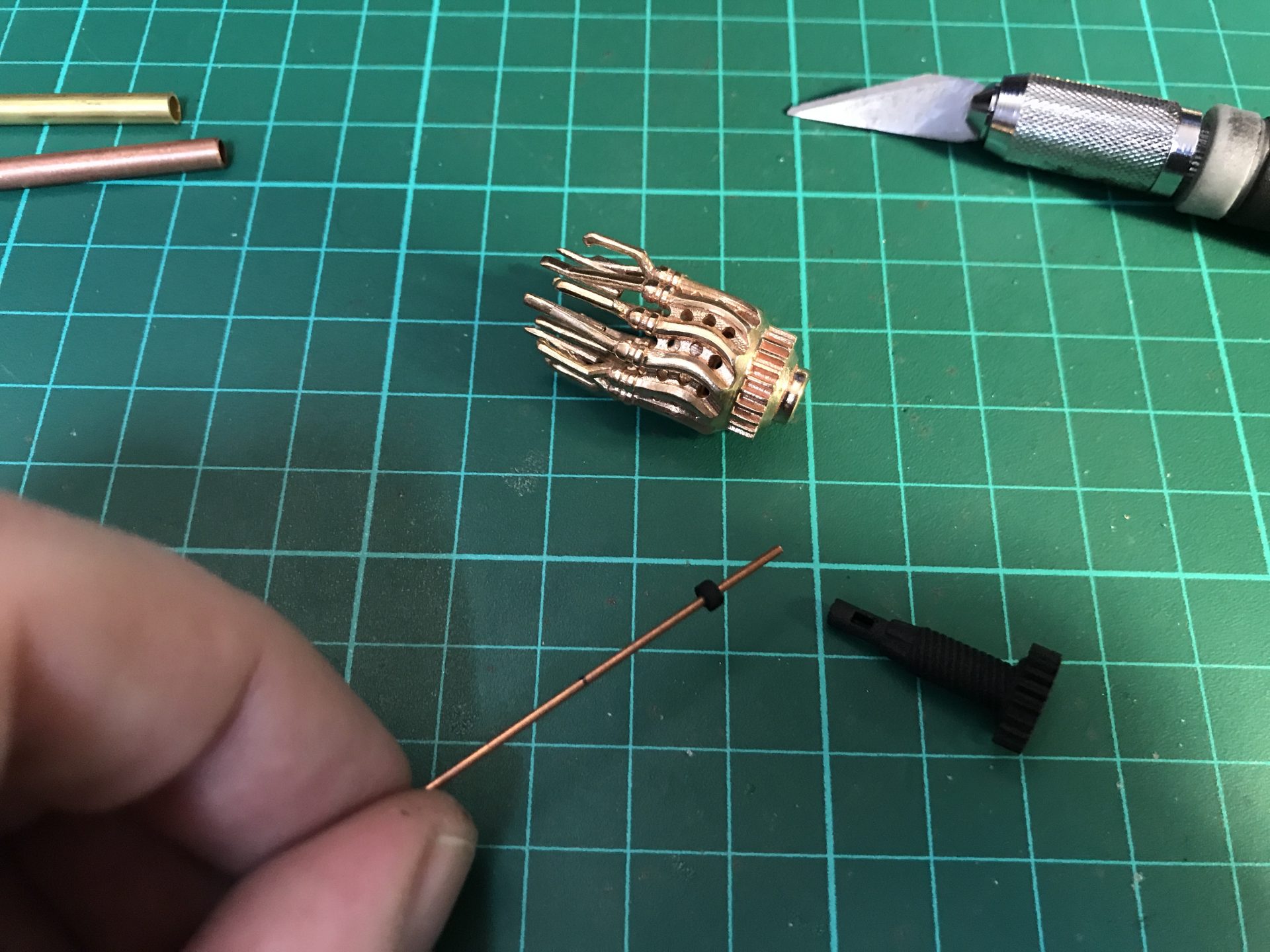
Step 23: Prepare and test the cycling devise chamber assembly. The gear plastic element contained in Part01 has a little plastic stopper part to be cut away and to be added on the other Rod 4) (1mmOD). This little plastic stopper part prevents the cycling devise from sliding once installed. So you have to test the placement first to measure where the rod and stopper will be positioned in the chassis.
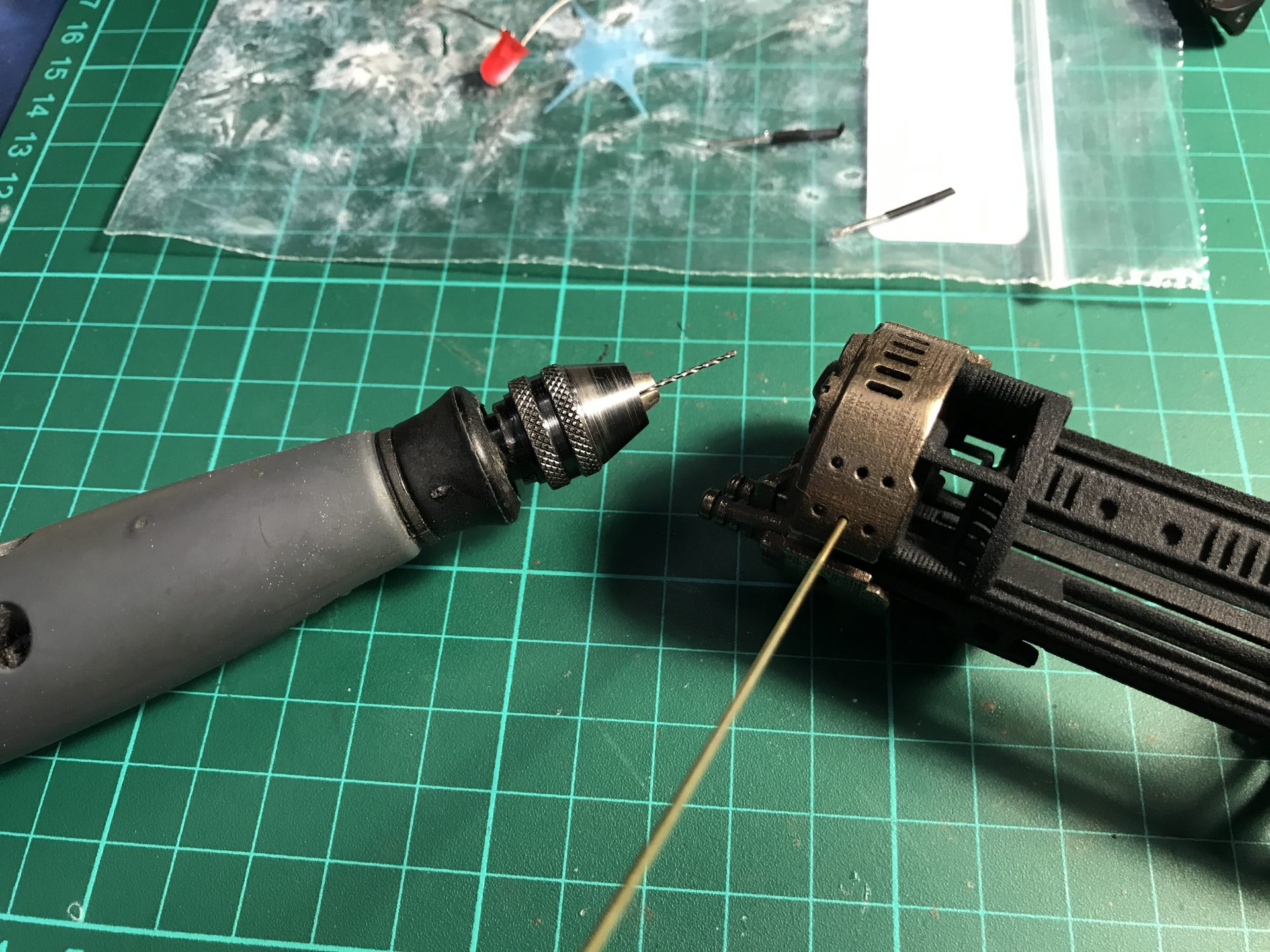
/! this is a tricky assembly, take your time to get it right and use the top tube as shown below to have the proper chassis placement. Note the it is probable the plastic parts holes for the 1mmOD rods will need cleaning to remove printing support dust (you can use a drill bit for that).
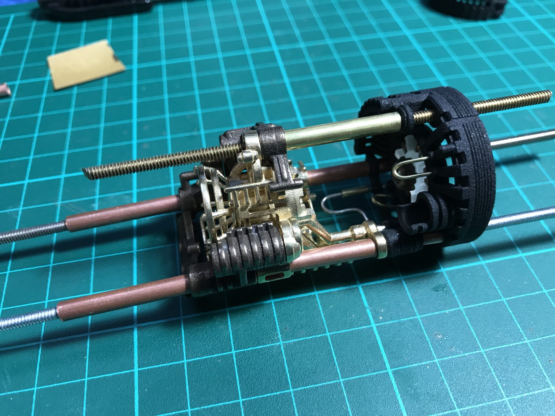
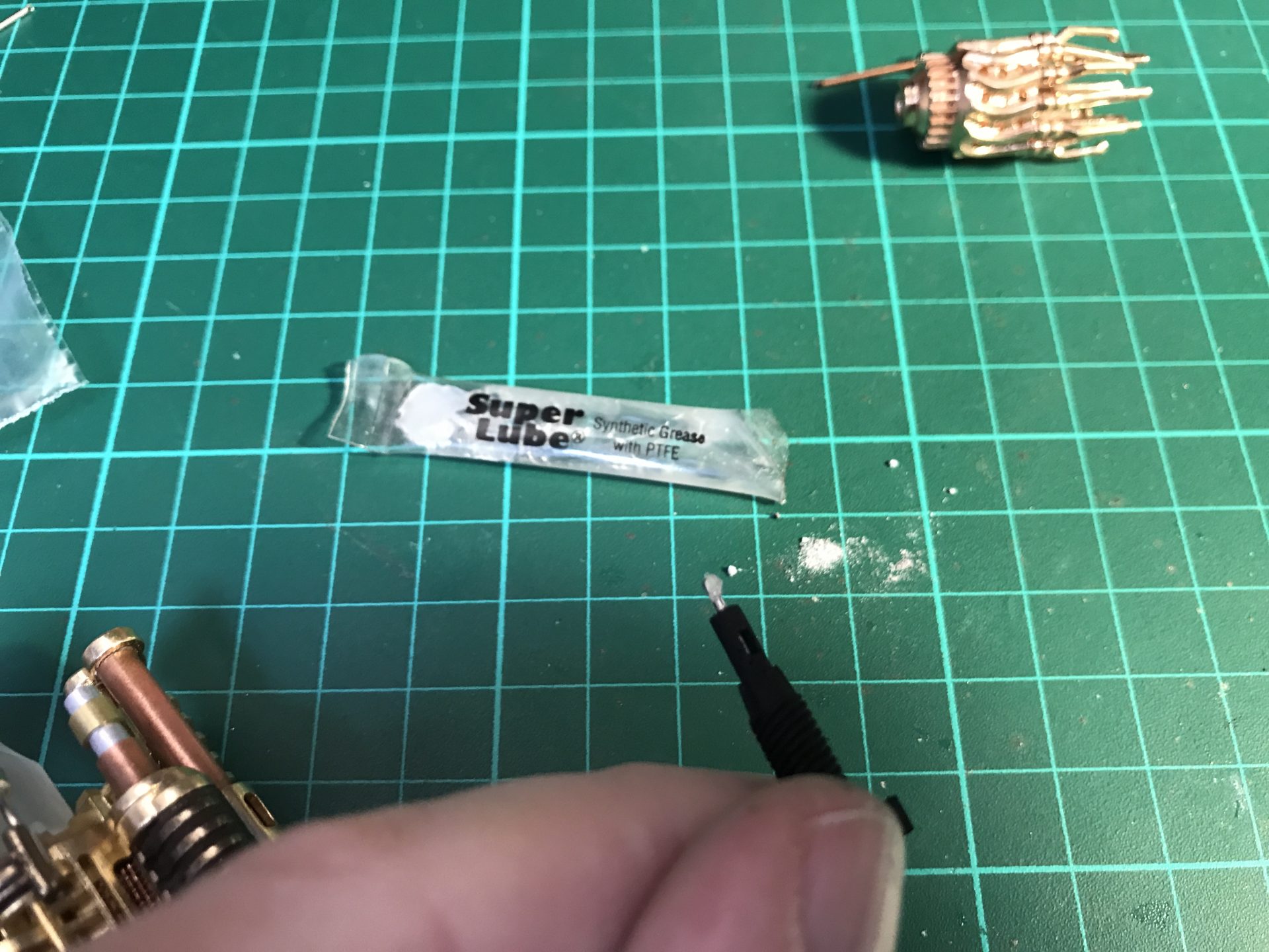
Step 24: Prepare the gear element and install (glue) the Rod 4) in it. Make sure the hole in Part06 is clean and smooth (cleaning will be required if printed in steel), and add a bit of lube to reduce friction.

Step 25: Prepare the remaining tubes and make sure they slide / fit well. As usual, if the parts are printed in steel, some cleaning will be required. And test again the whole assembly to make sure everything fits properly.
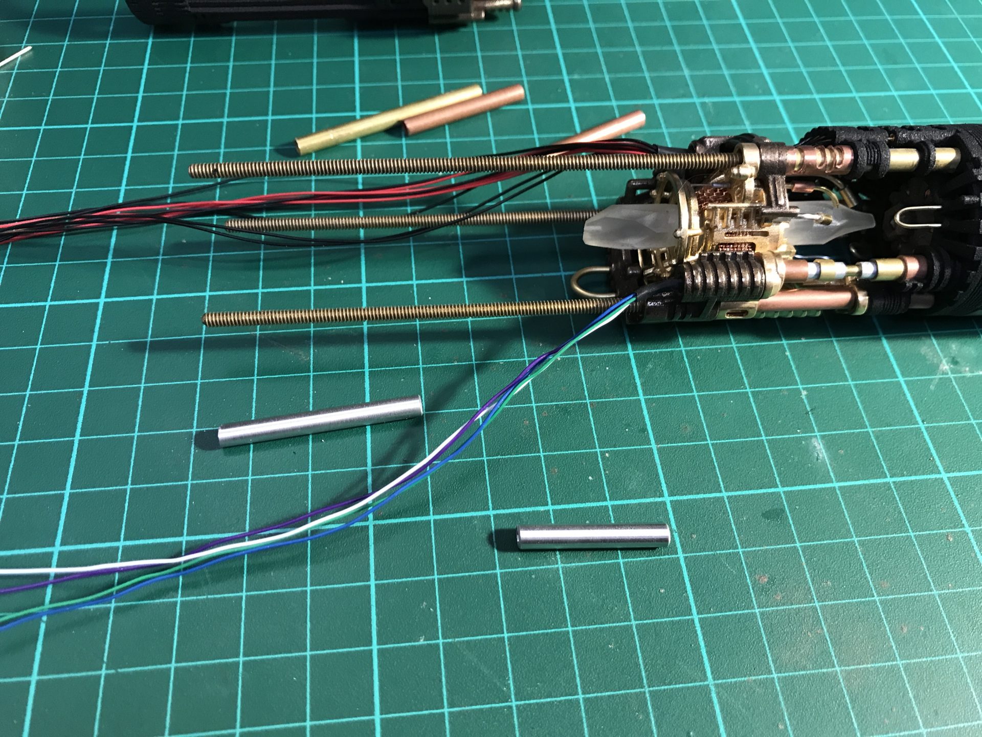
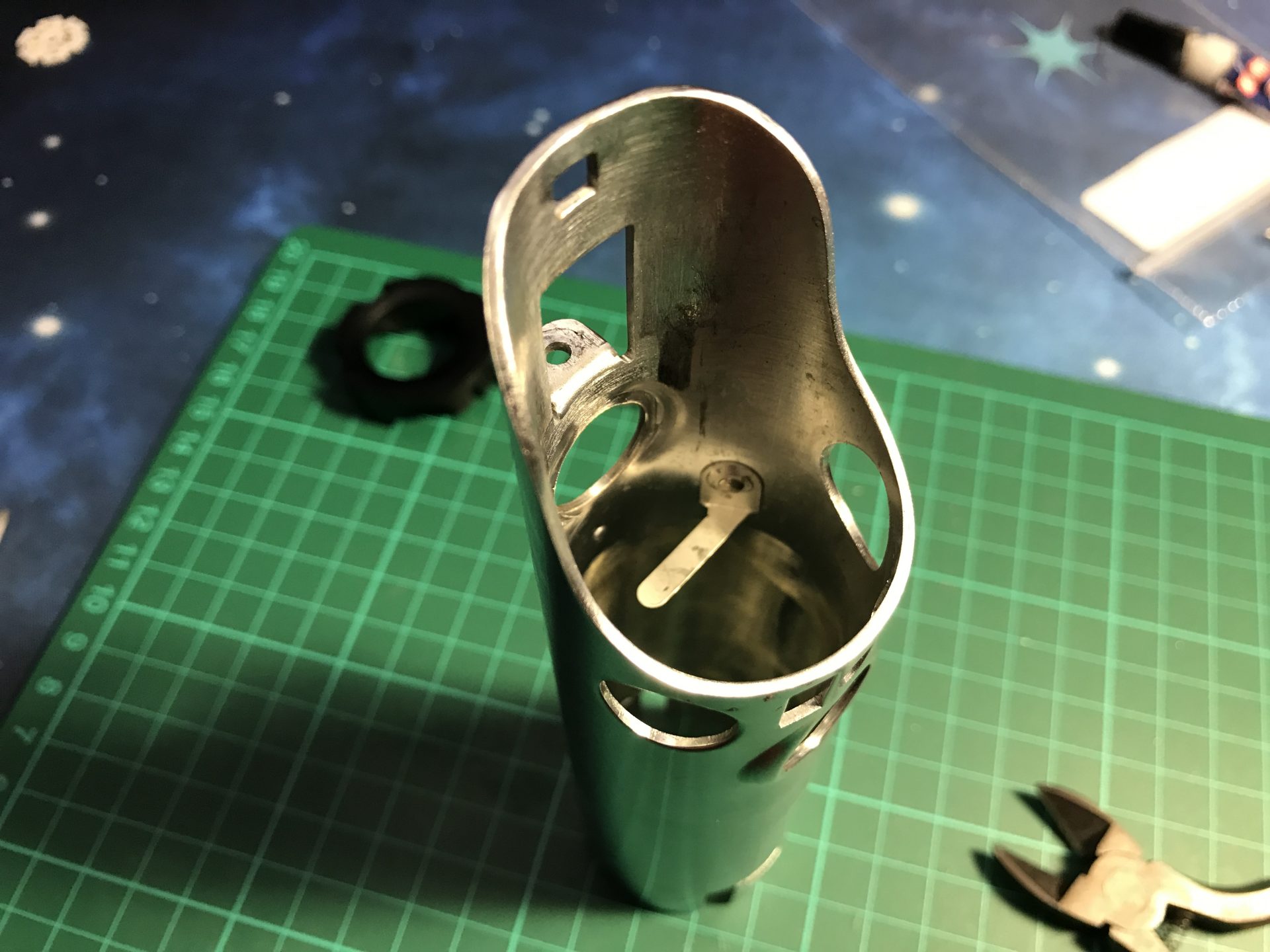
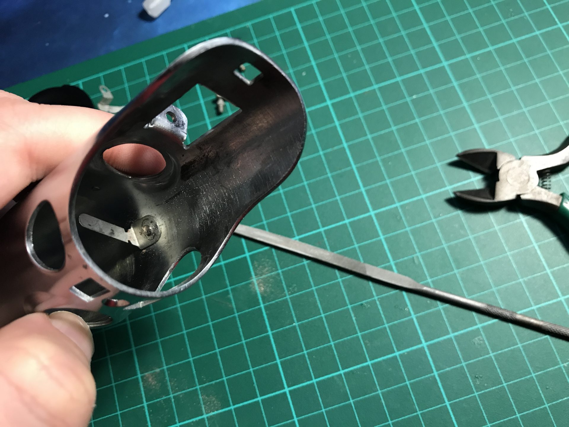
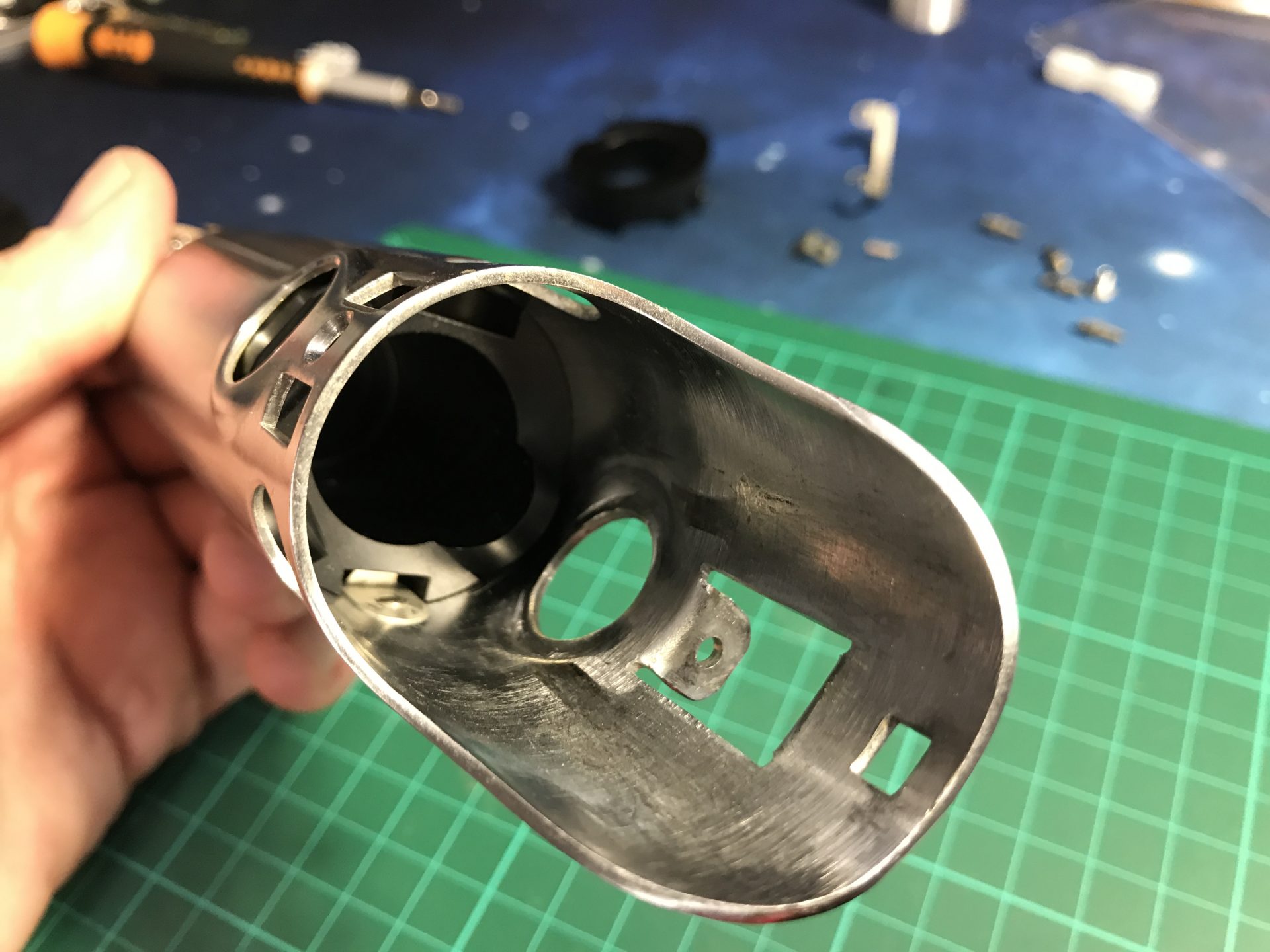
You’ll also have to clean the holes on the side as shown below, that matches with the main soundboard chassis. These holes will serve to secure the main chassis to the rest of the chassis assembly later using 1mmOD rod pieces.
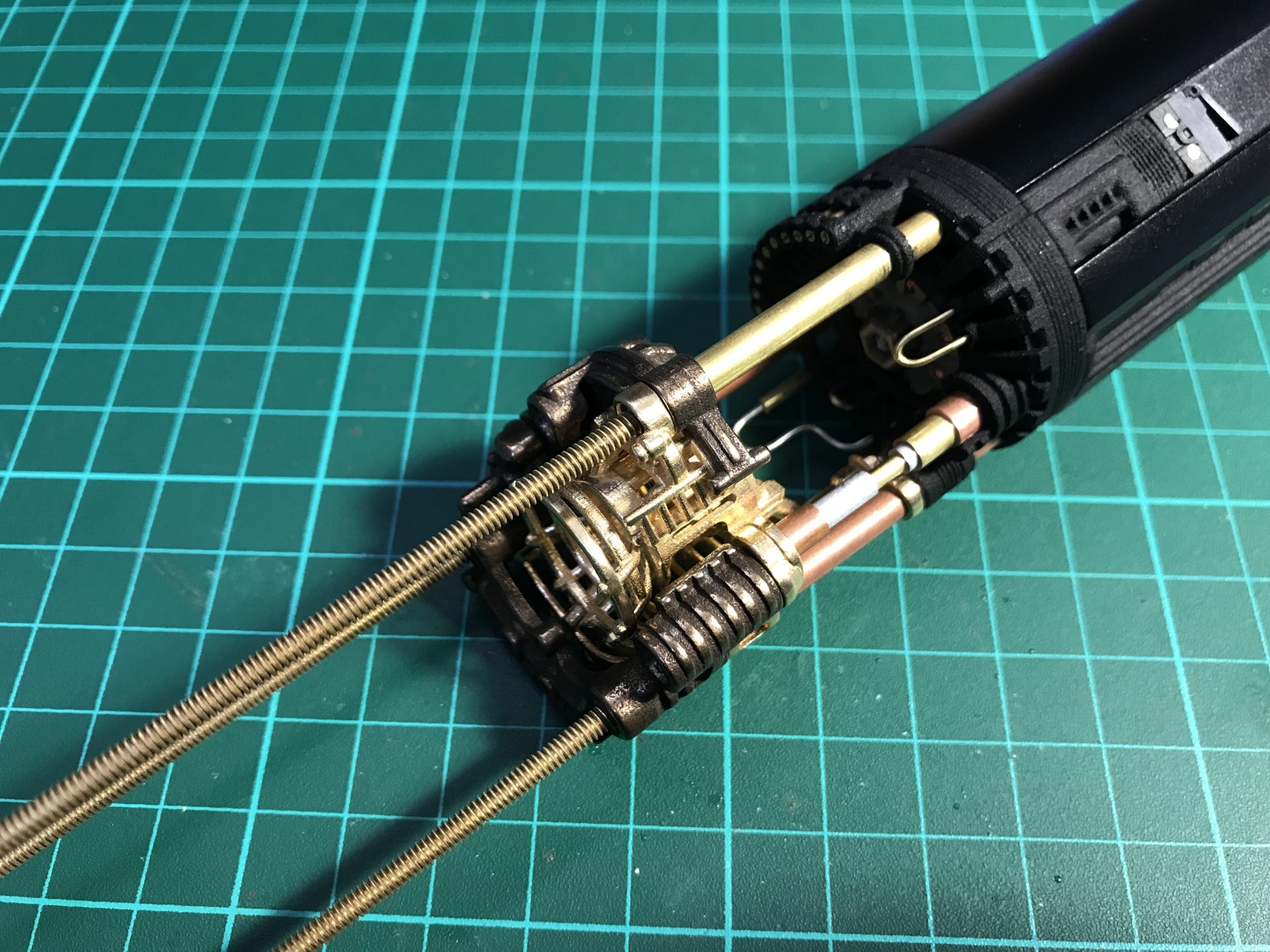
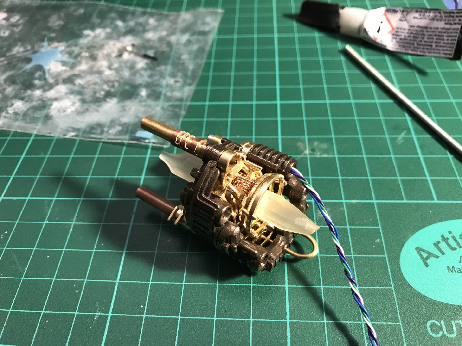
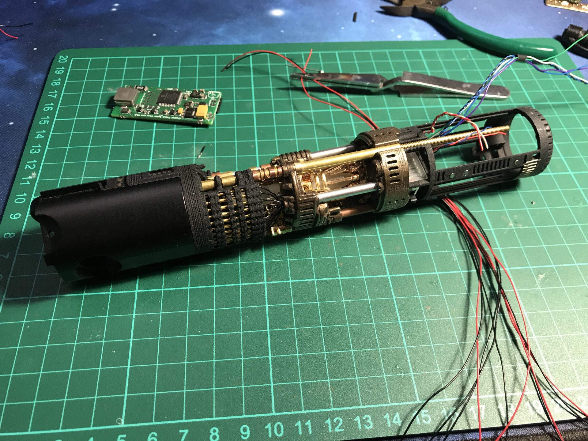
Step 26: Pass the wires into the dedicated channel tubes. Then glue the tubes to Part06, the add part12 and glue the tube to it as well. Make sure the whole assembly is strong enough,
Step 27: Glue the 2mmODx1mm magnets into the two cover plates and main chassis.
/! Important: again, make sure you respect the magnets polarity. Both plates have the same set of magnets so that they can be switched and compatible on both sides of the main soundboard chassis.
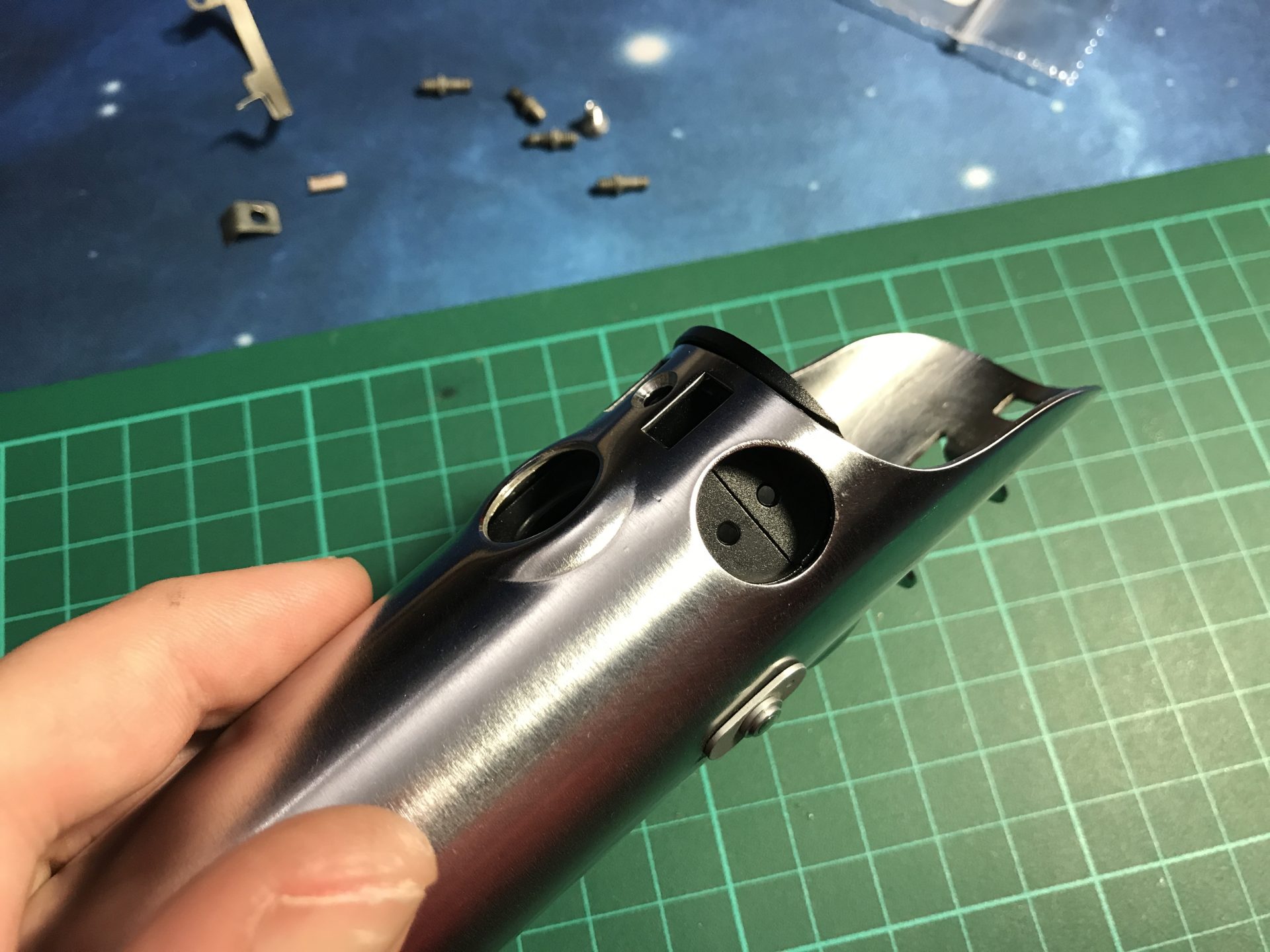
Step 28: You can add the rods 6) (0.5mmODx7mm) on the main chassis.
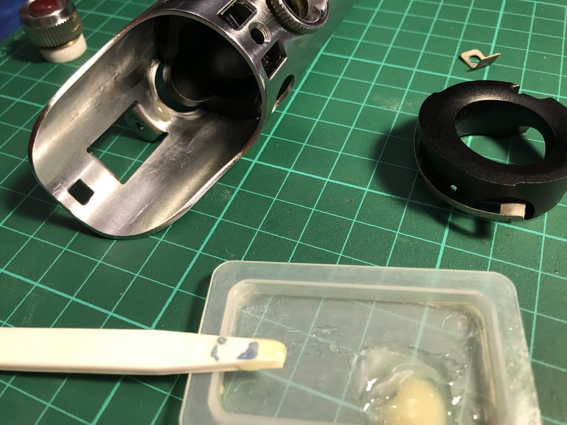
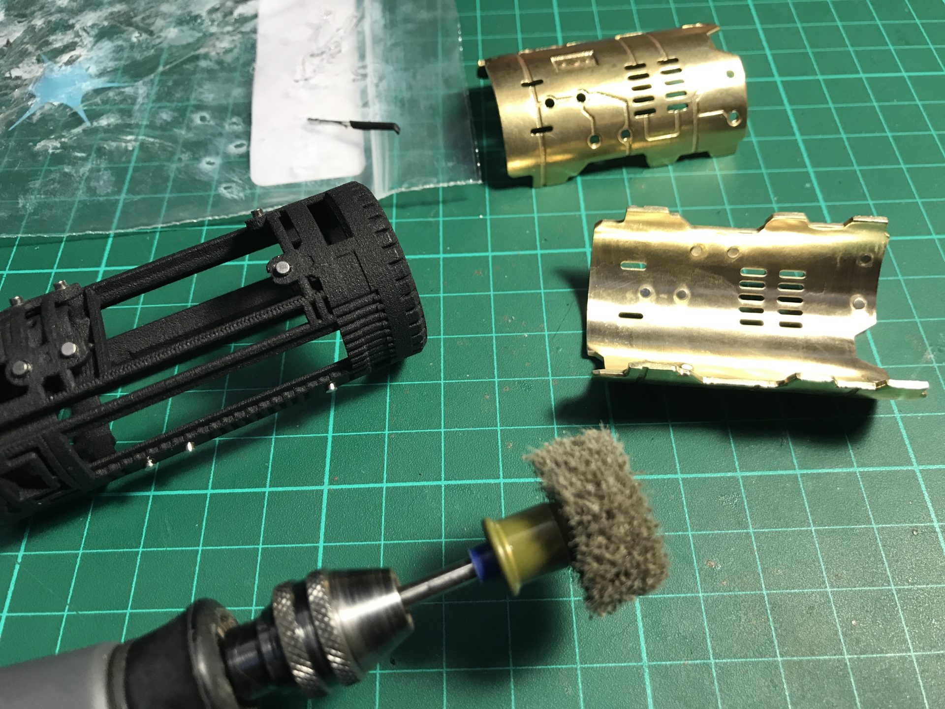
Step 30: It would be necessary to sand the interior of the speaker cover to make it fit properly (if printed in steel). We usually sand it until it press fit without to much force, and stay securely in place (while still be able to remove it).
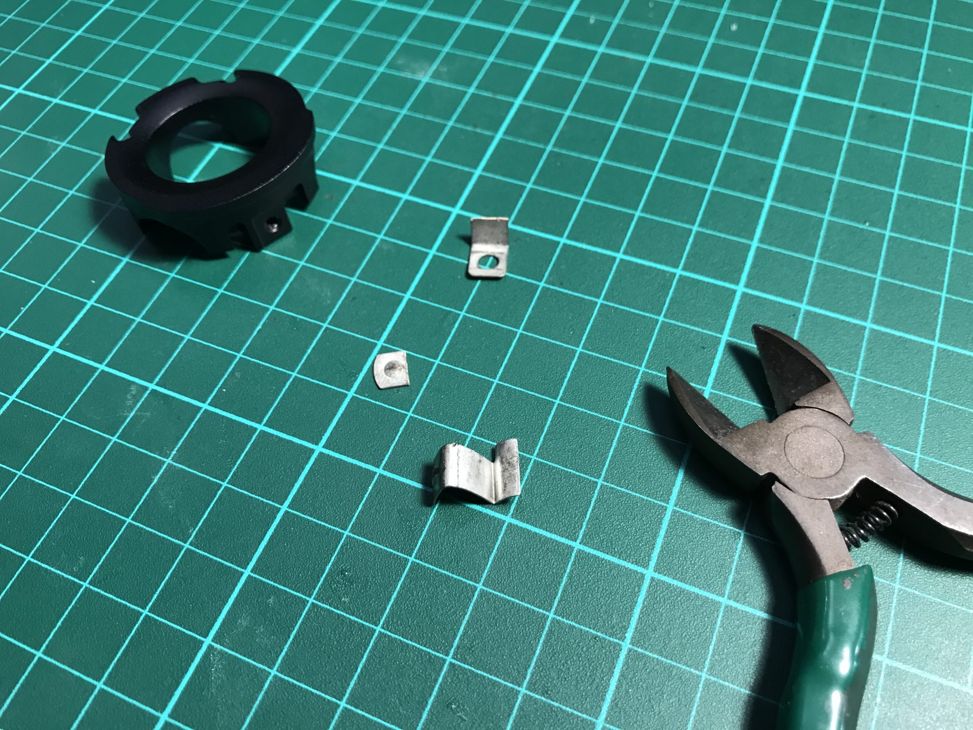
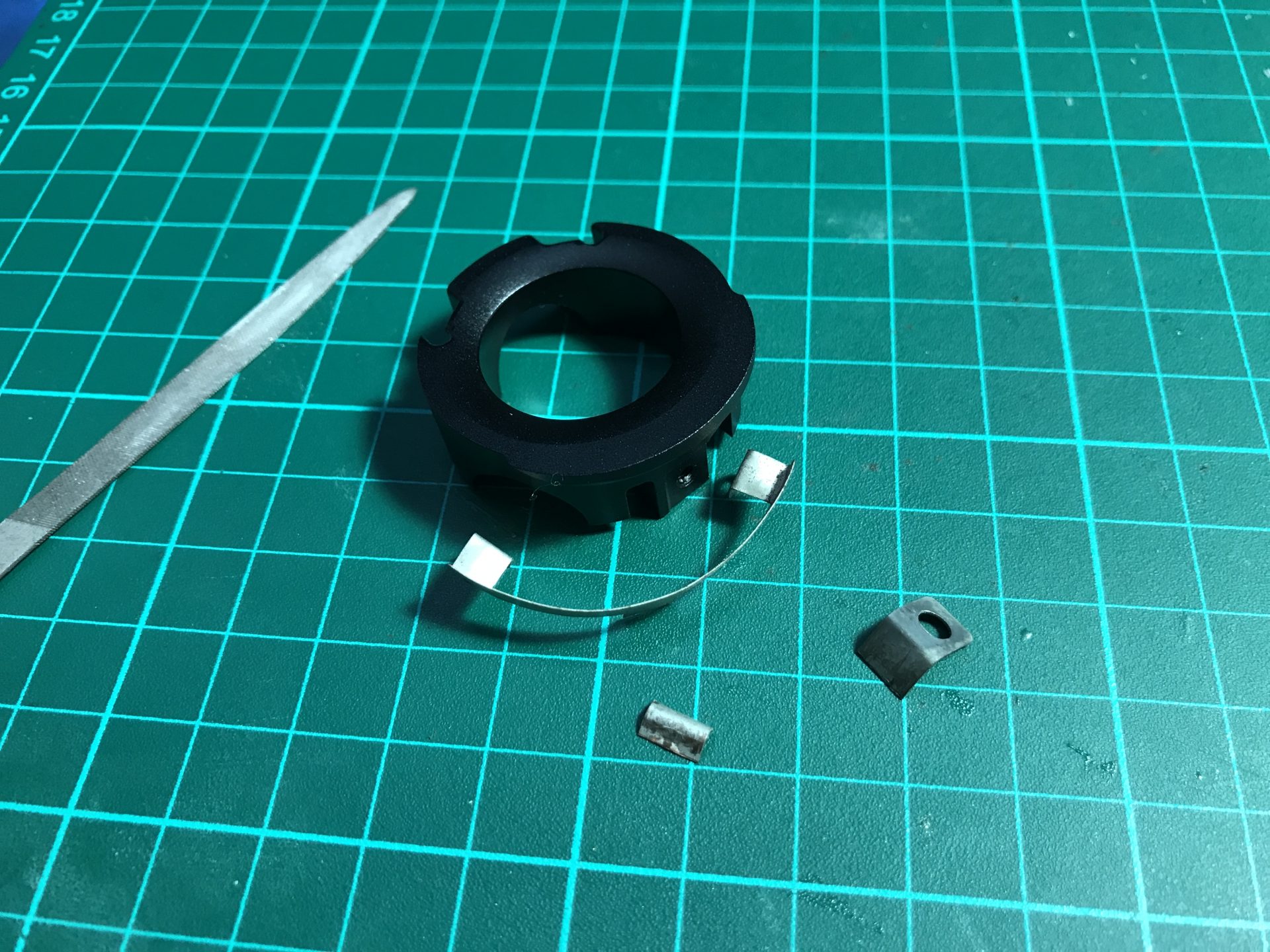
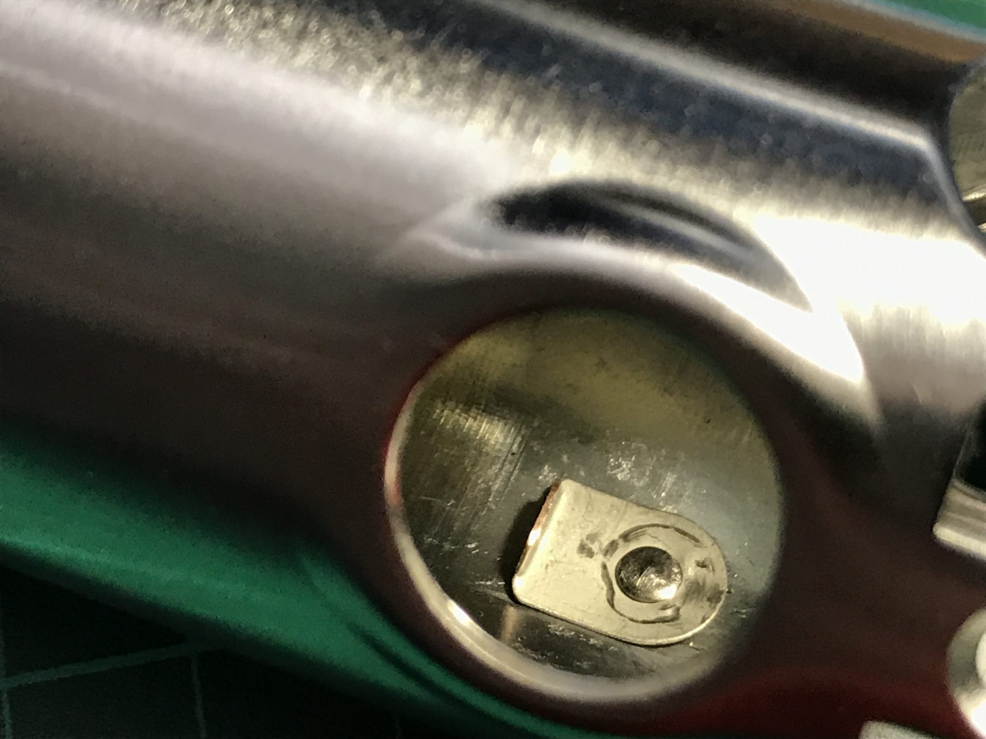
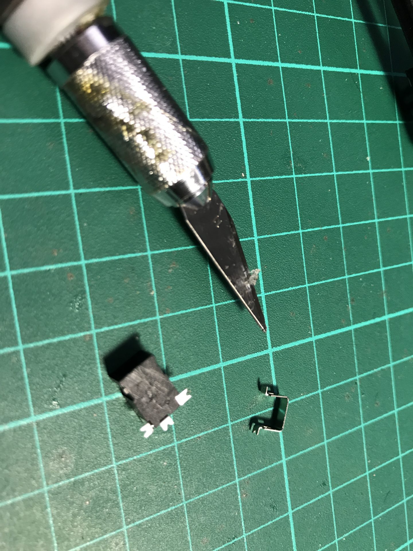
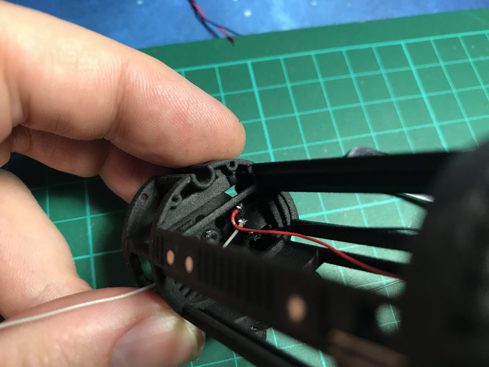
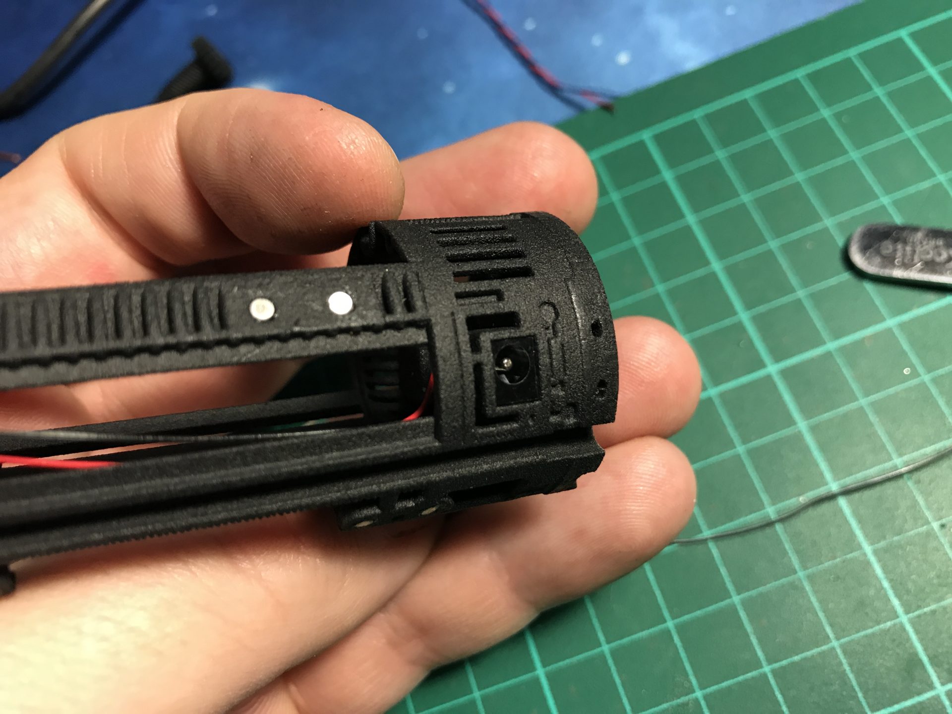
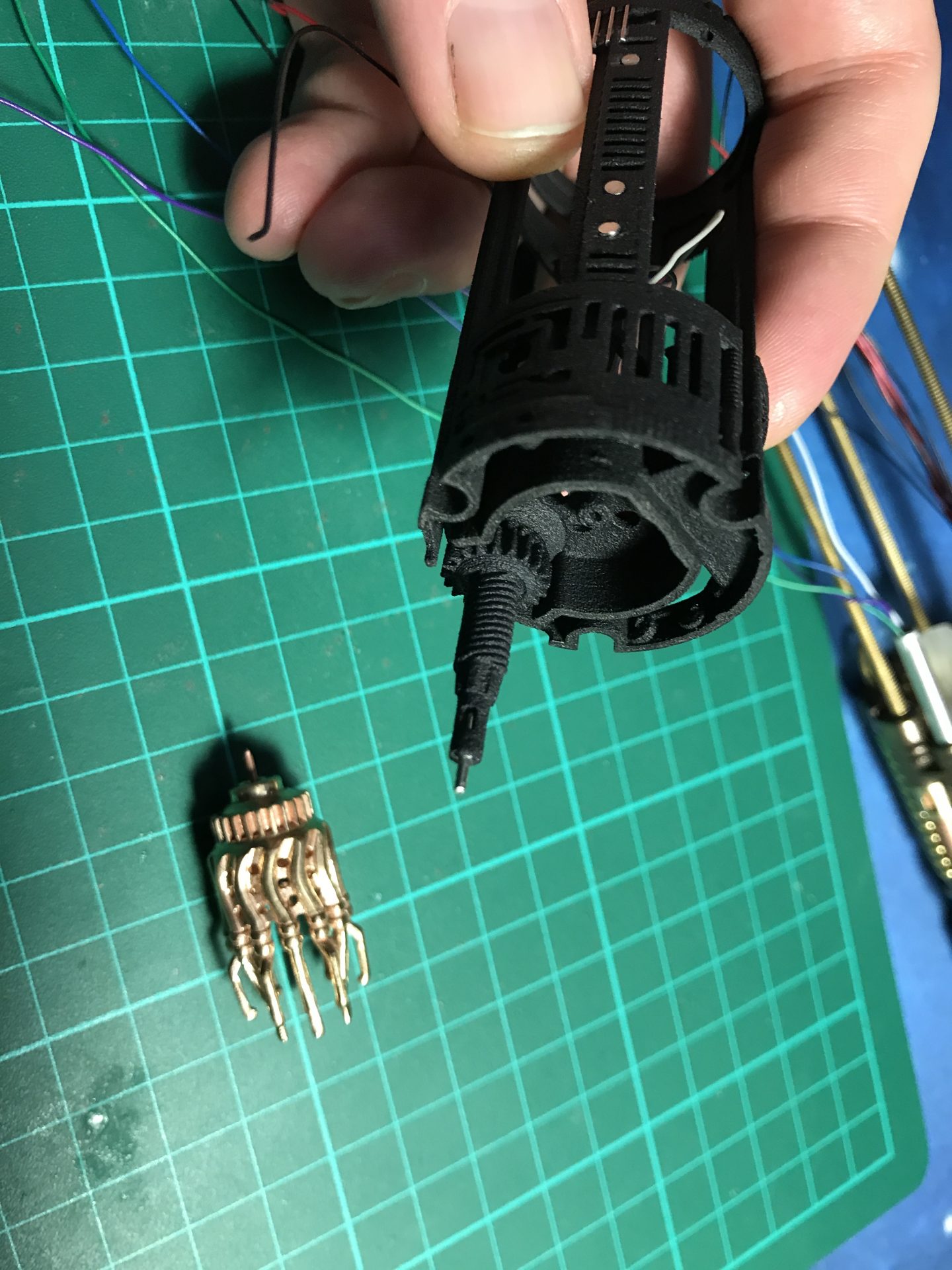
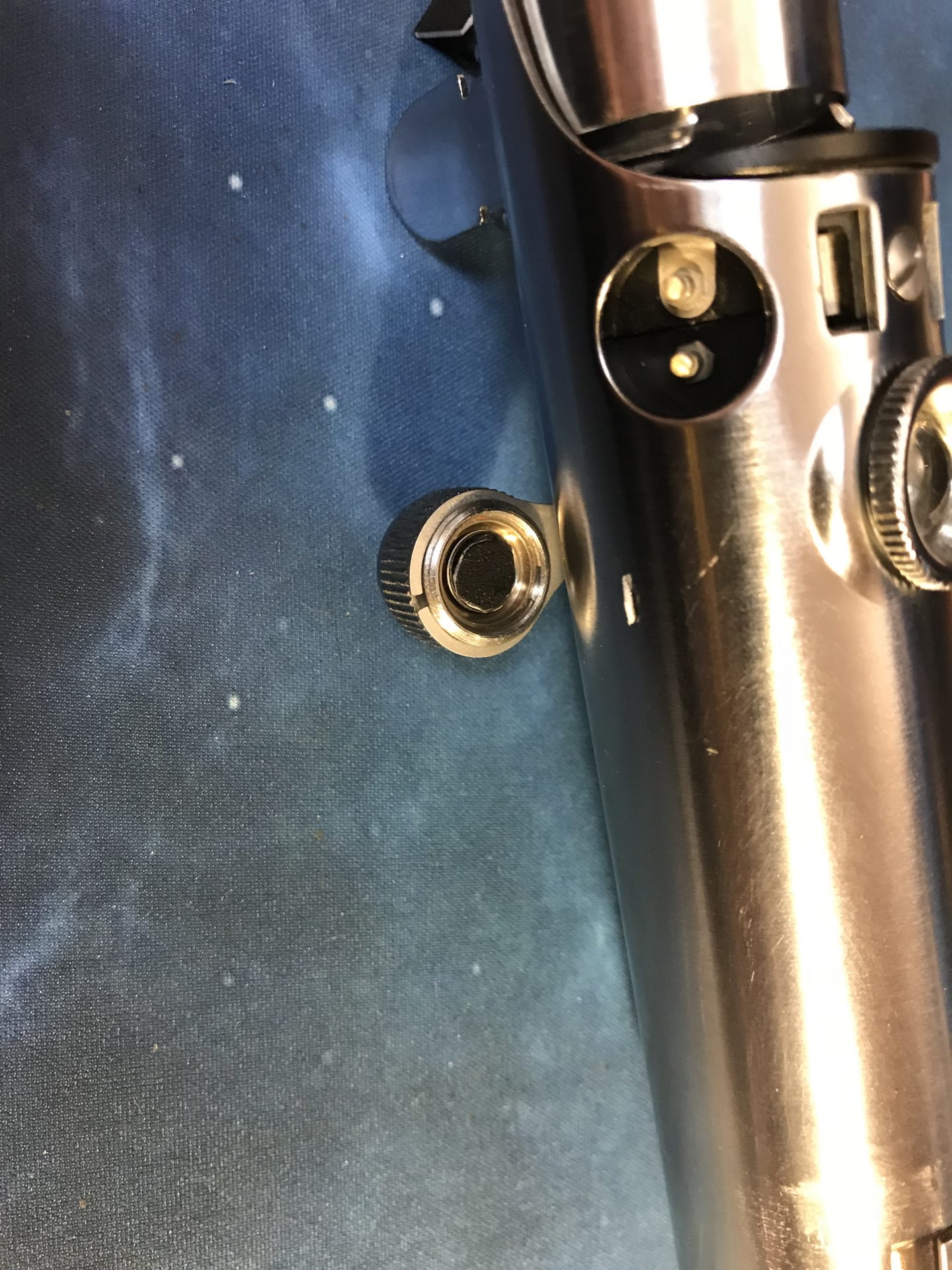
Step 31: Install the 1.3mm Recharge Port. Remove the metal part as shown and cut down the prongs. Once wired as shown in the diagrams, insert it and glue it in the dedicated spot.
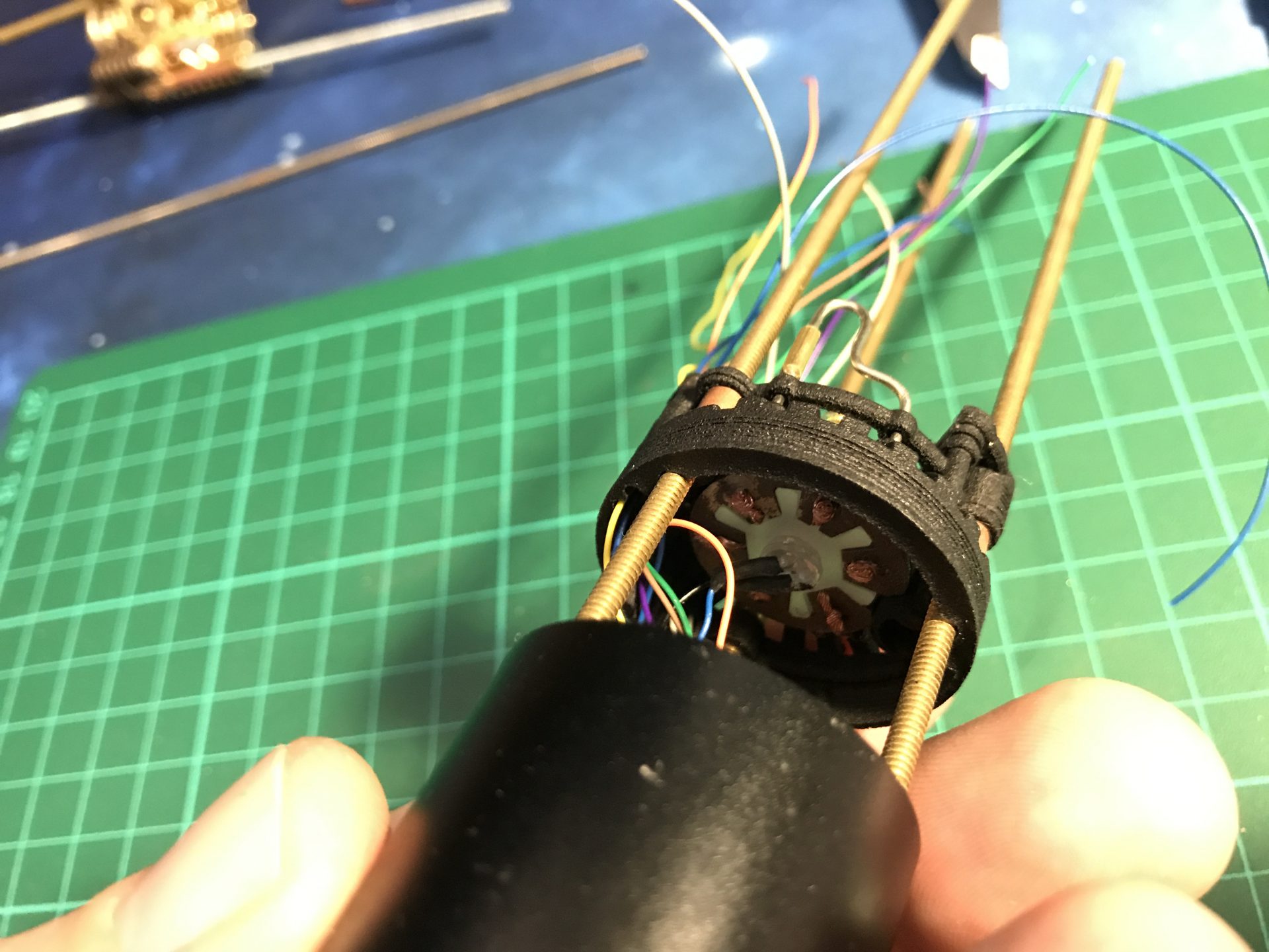
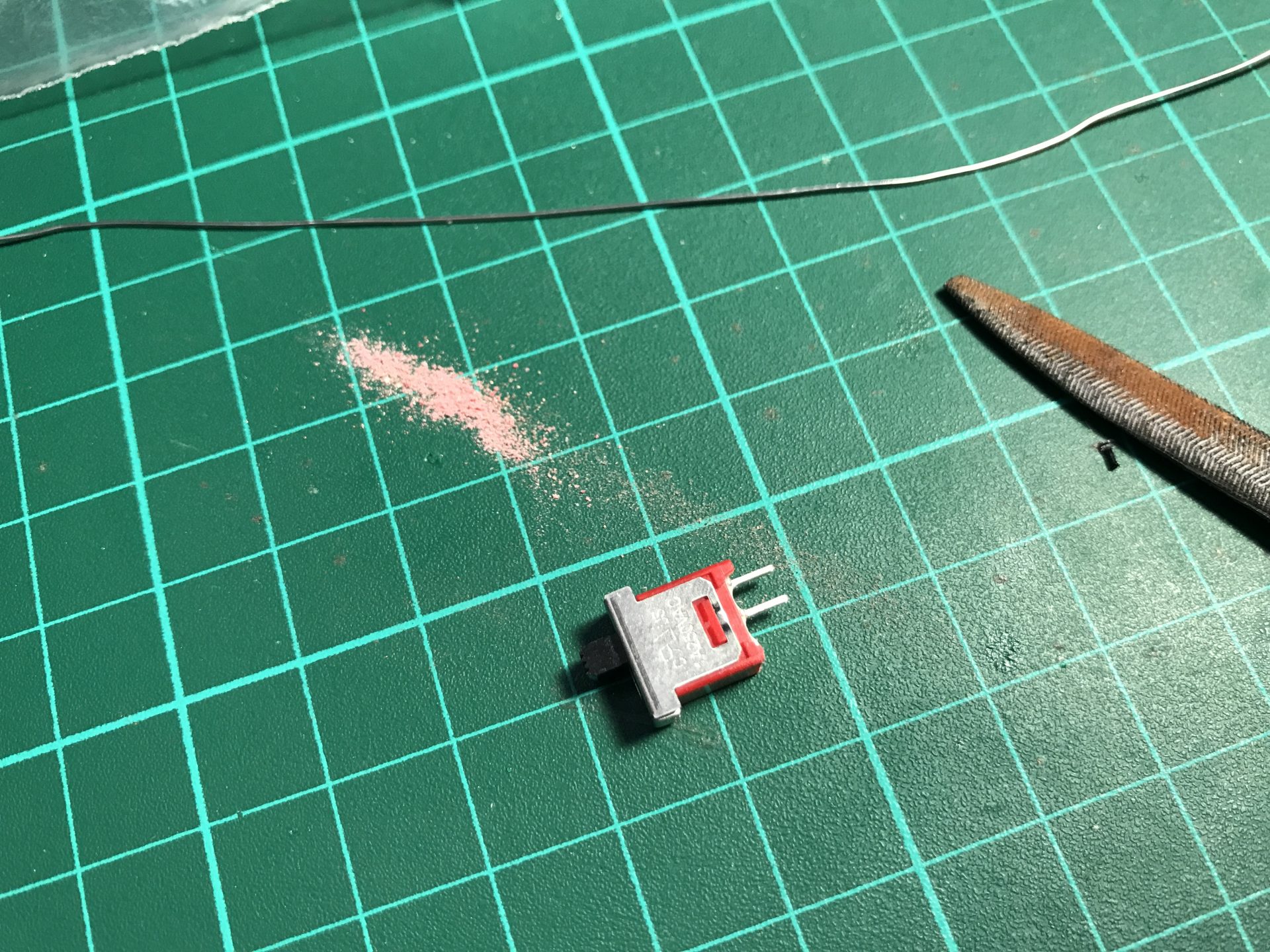
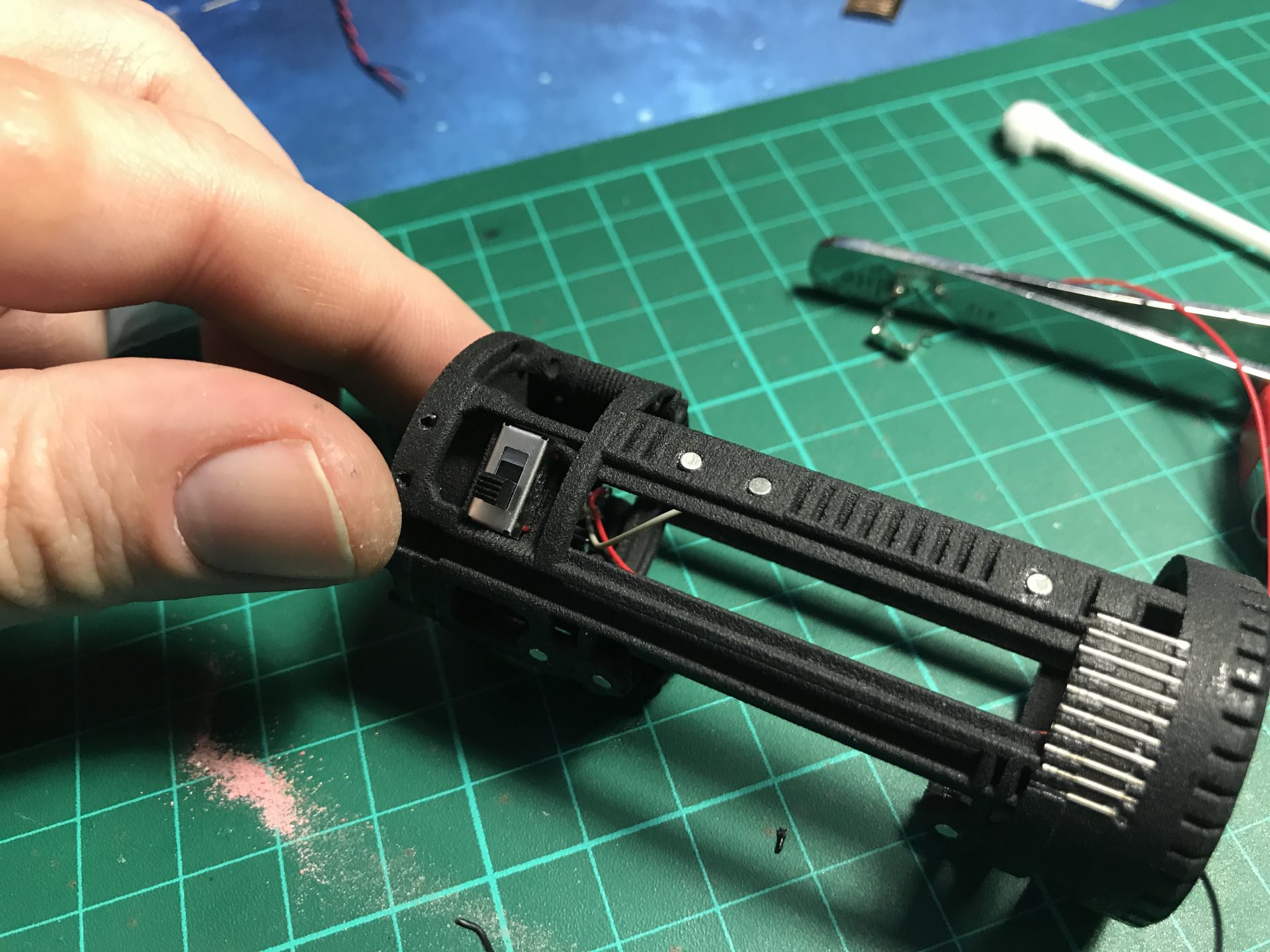
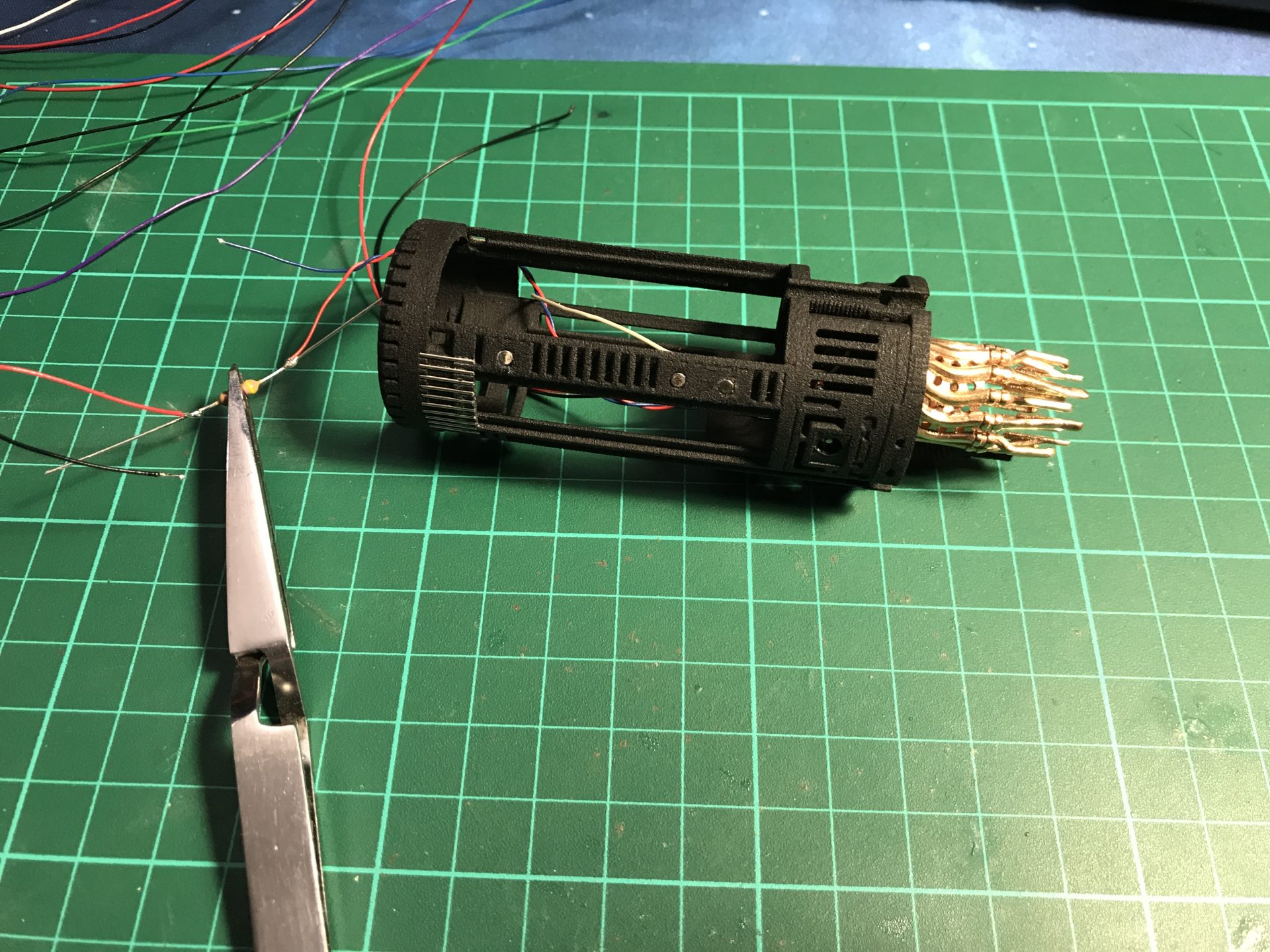
Step 32: Install the switch. Cut one leg and sand the switch down (that space is needed for an accent led later). Wire the switch with the soundboard negative wire coming out of the recharge port, then insert it.
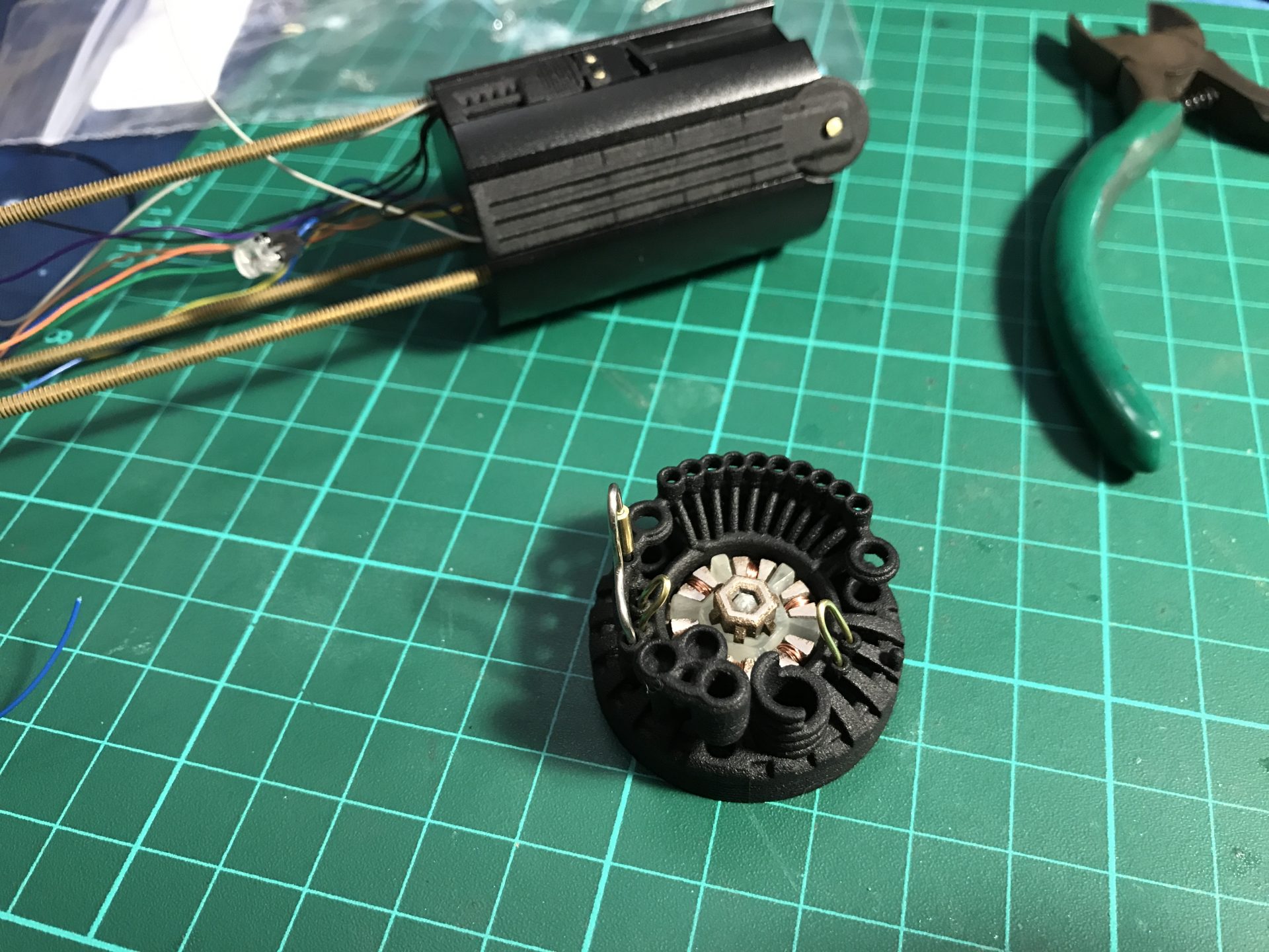
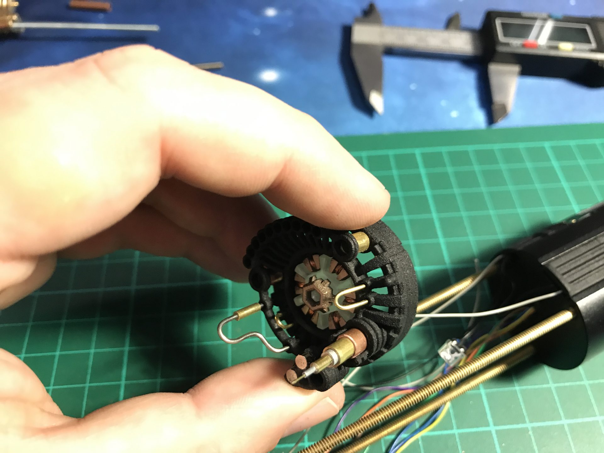
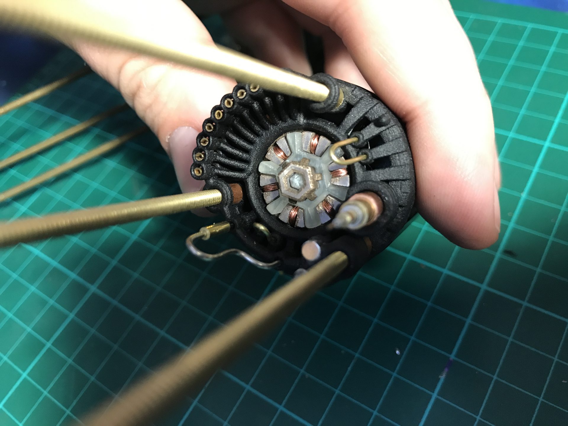
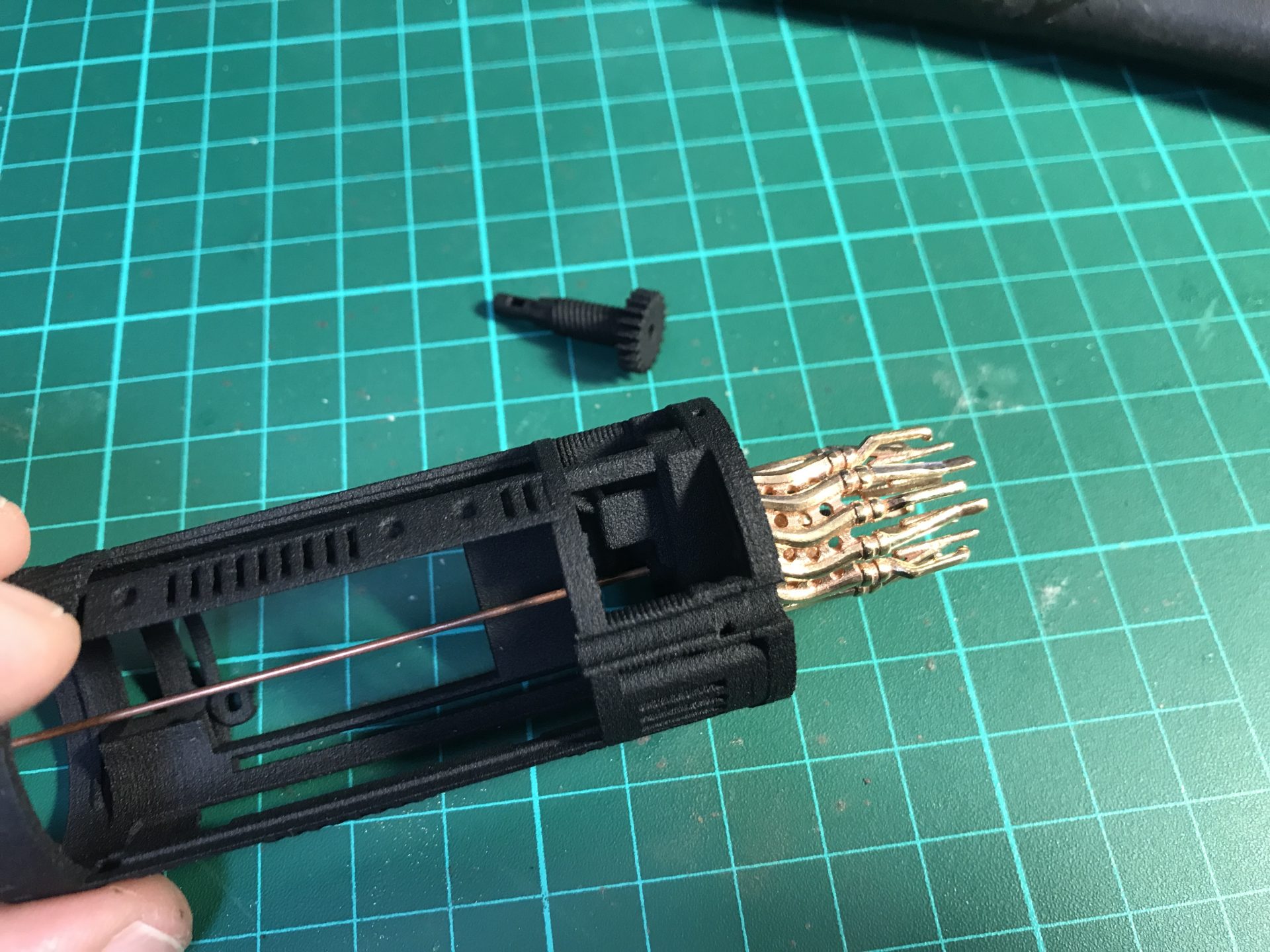
Step 33: Insert the motor into its dedicated slot and attach the gear part to it. Then add the cycling part to test.
Step 34: Install the accent led plate. Sand down the 3mm led to fit snug, and solder the wires. Then insert it into its dedicated slot on the main chassis and test it.
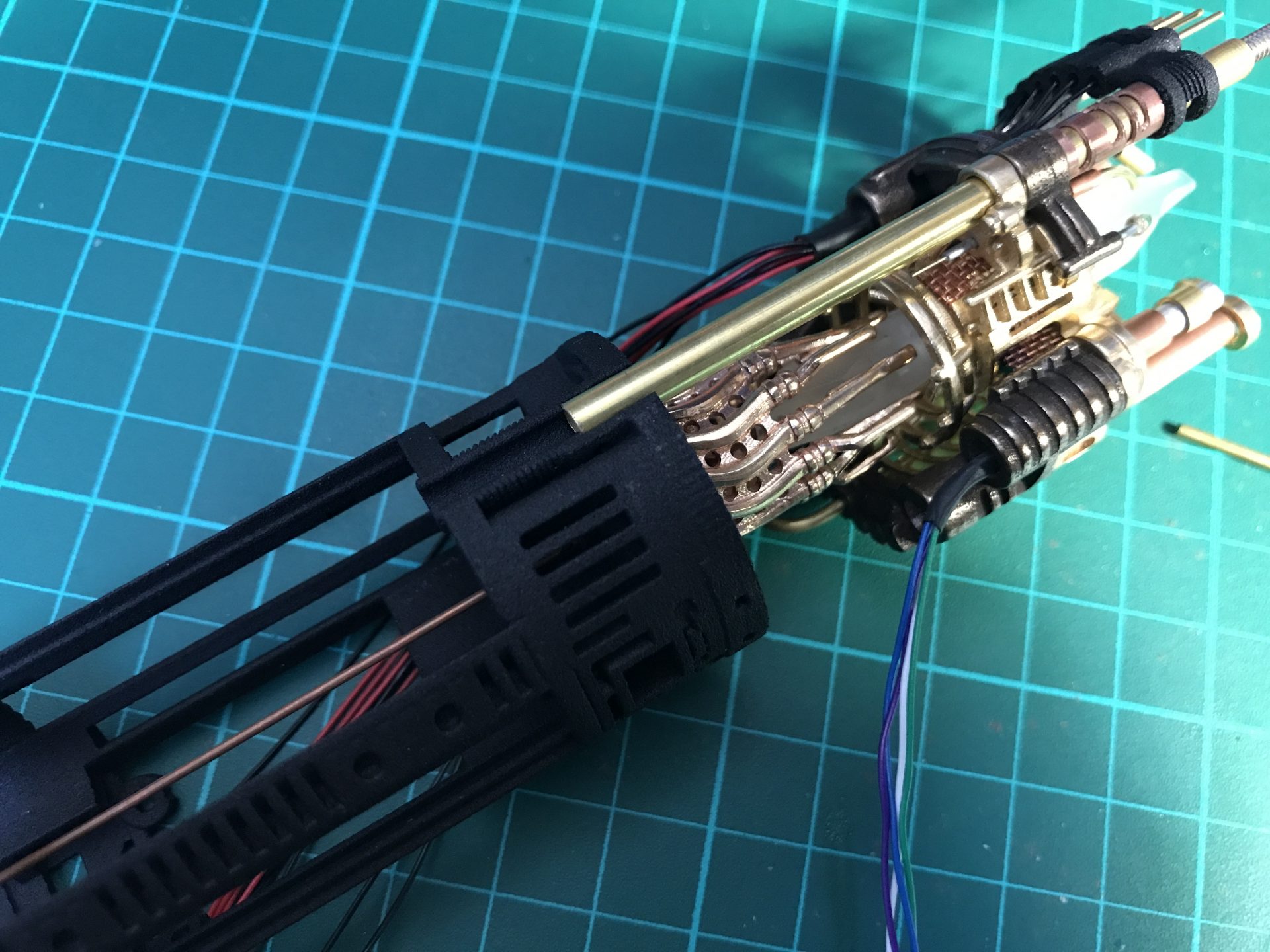
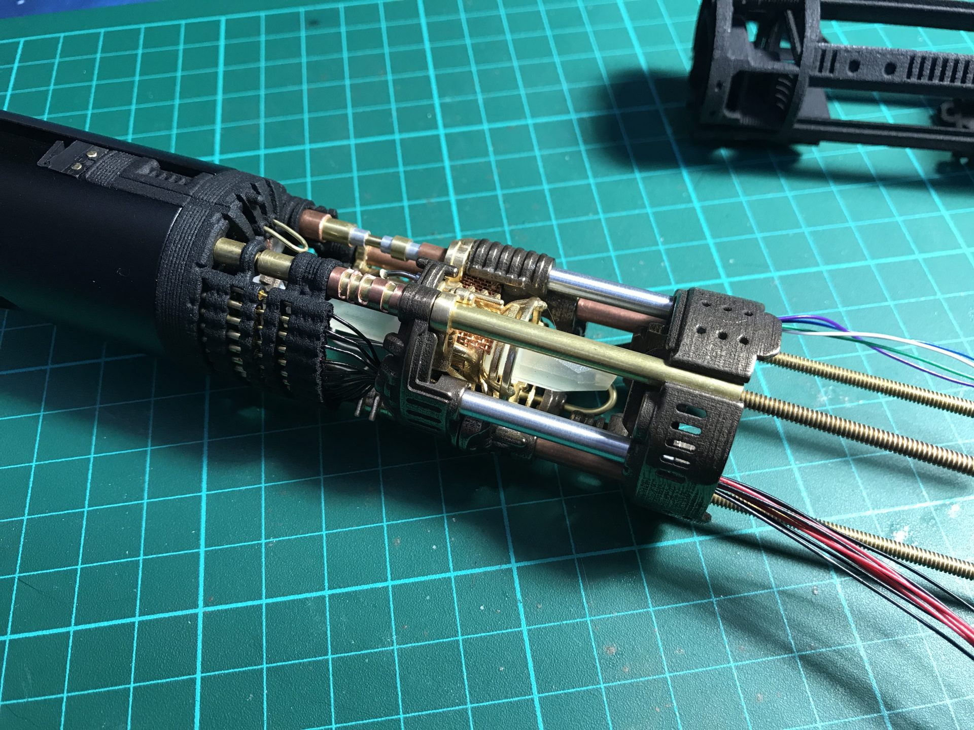
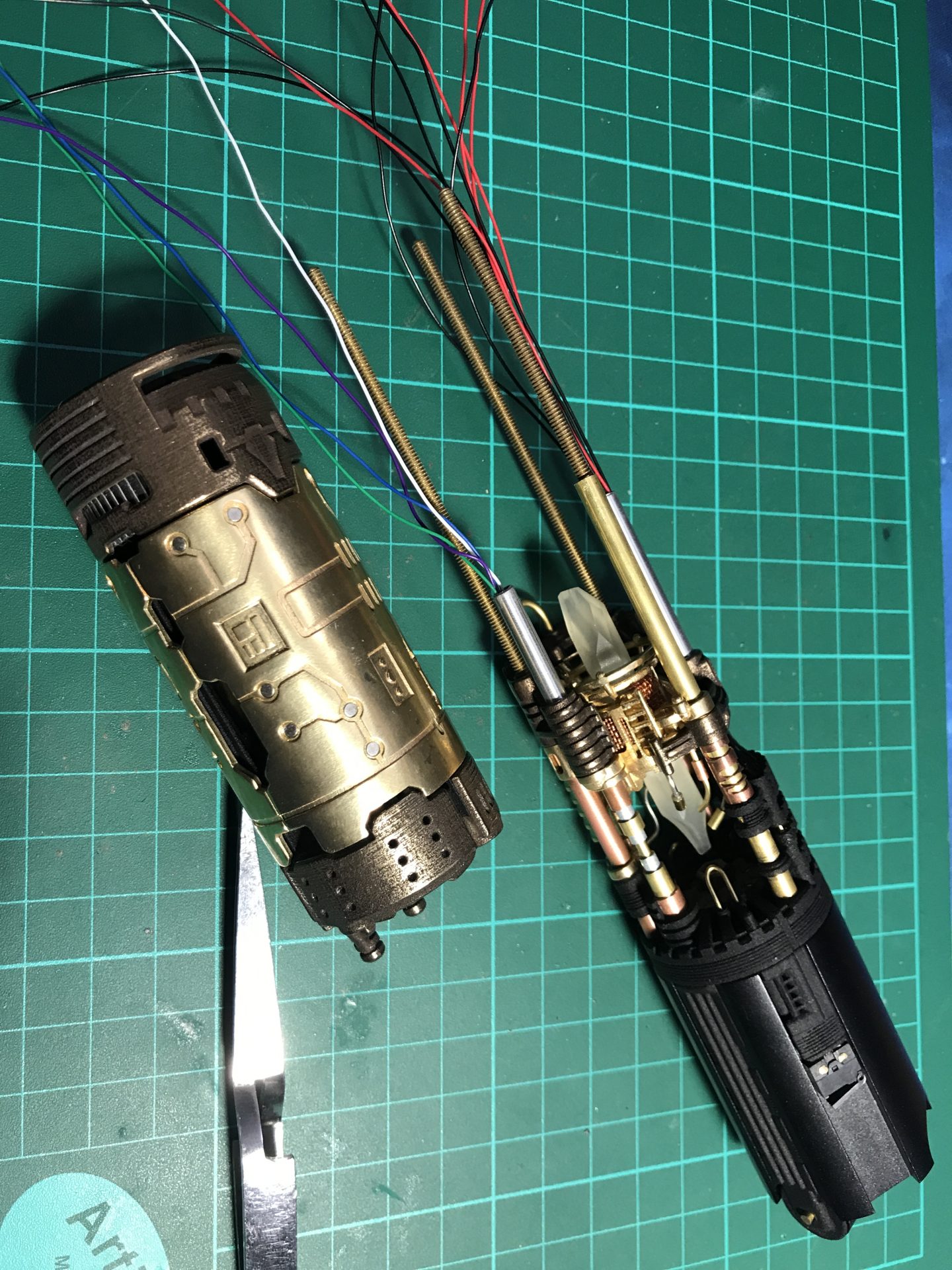
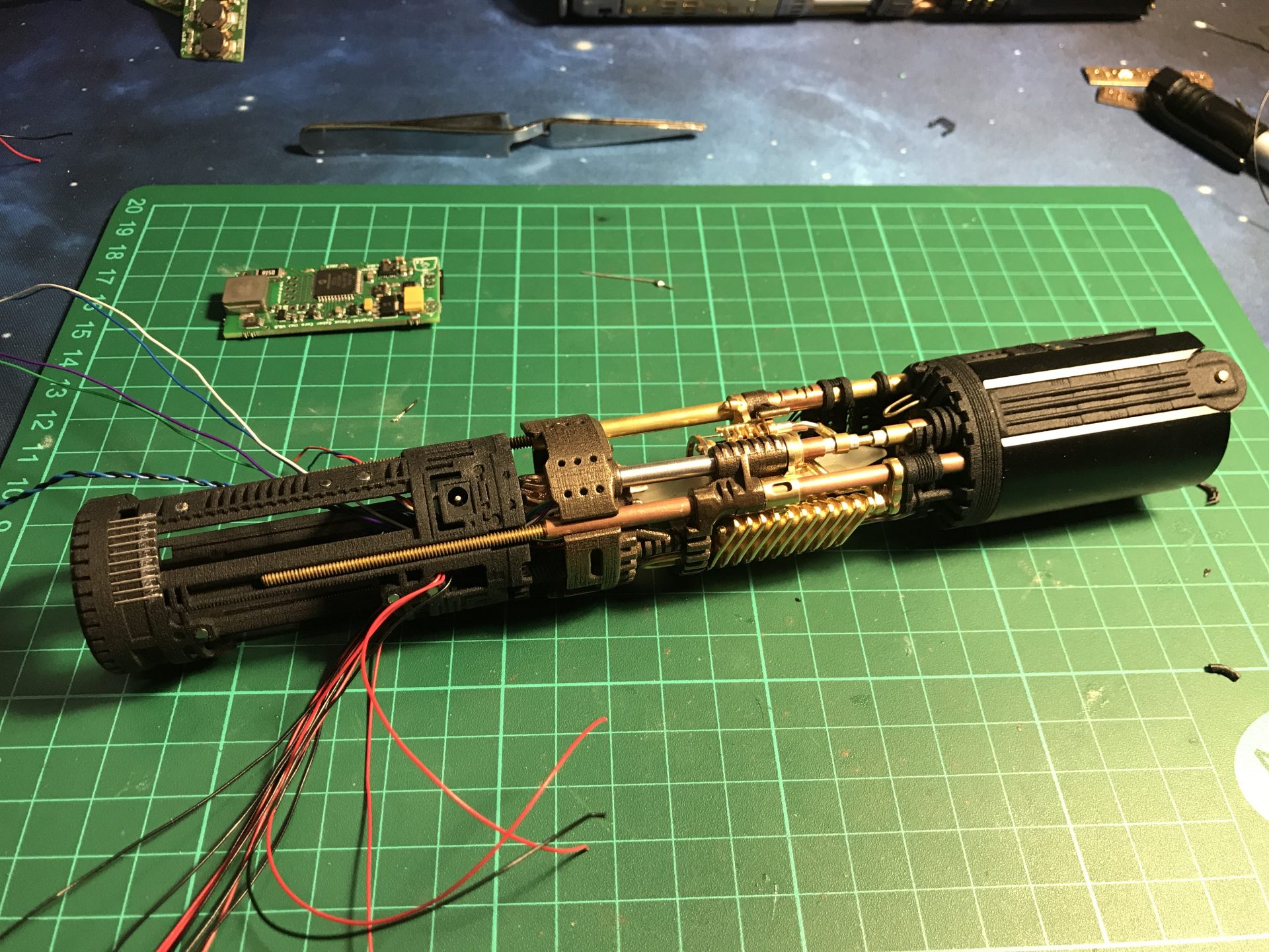
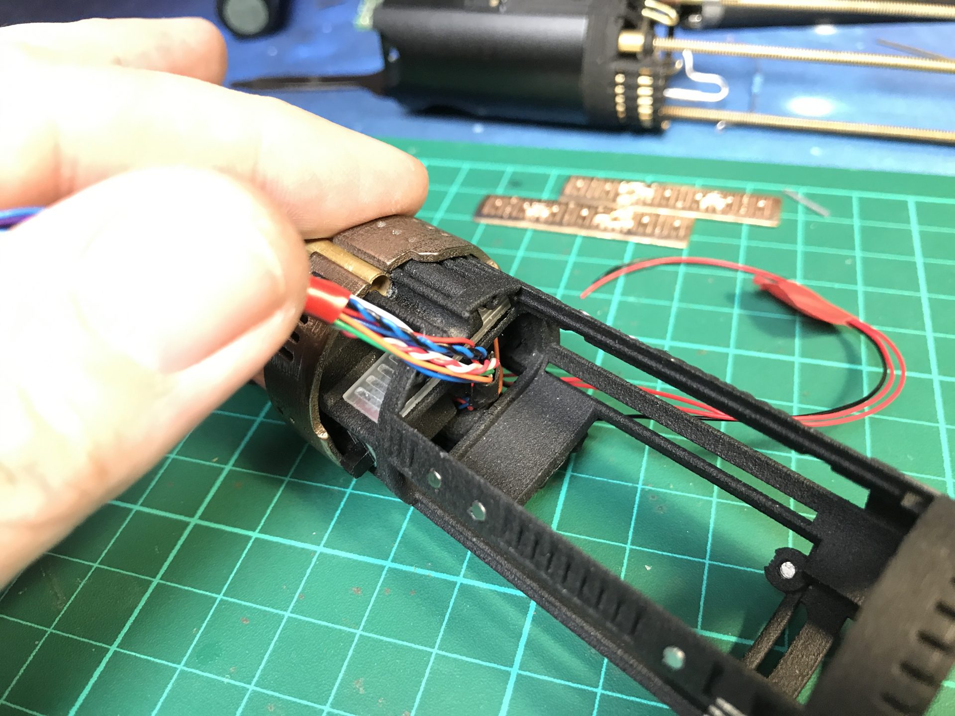
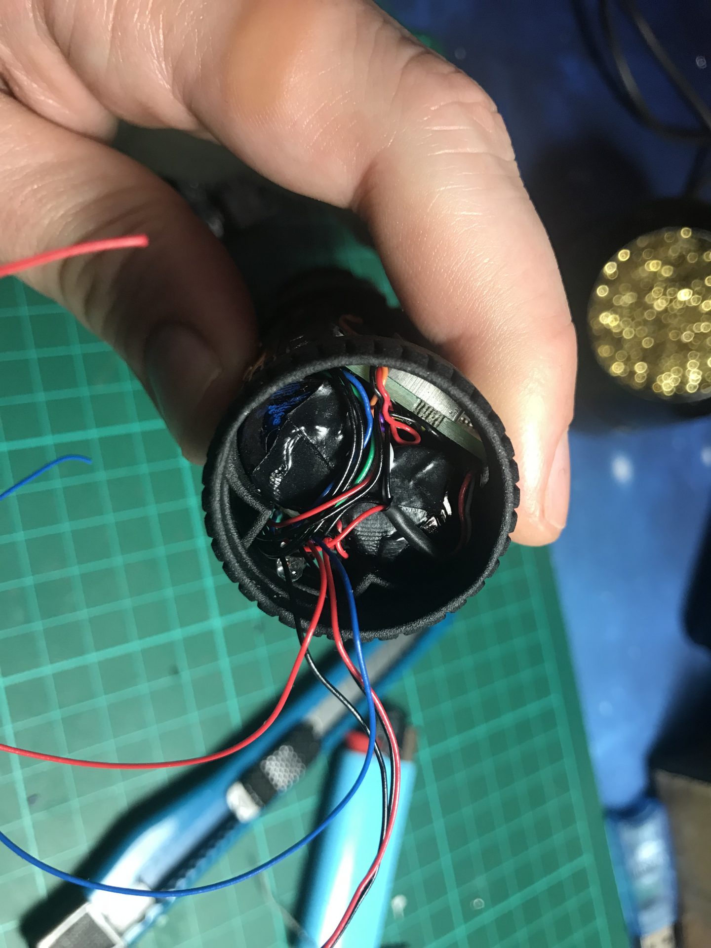
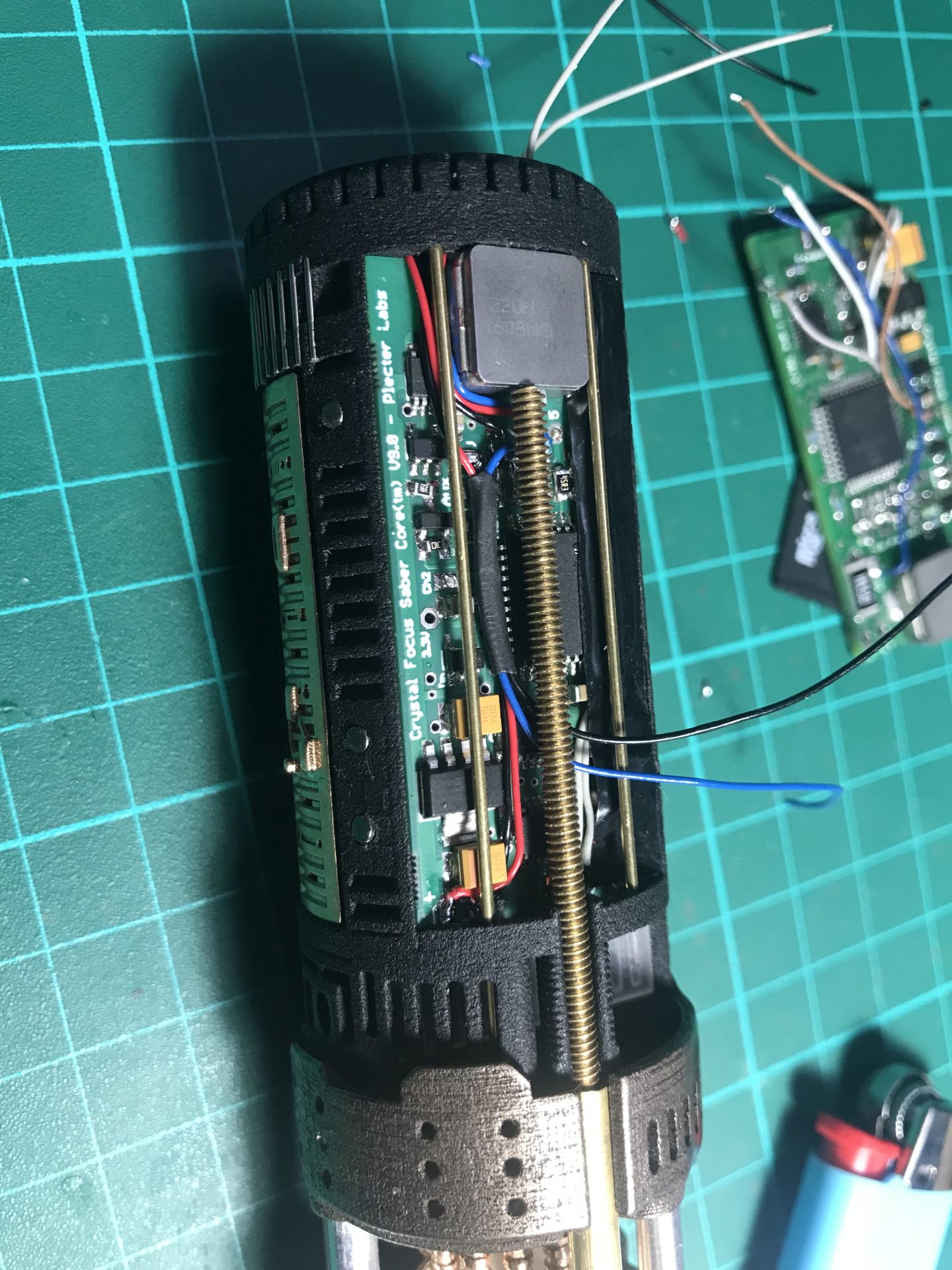
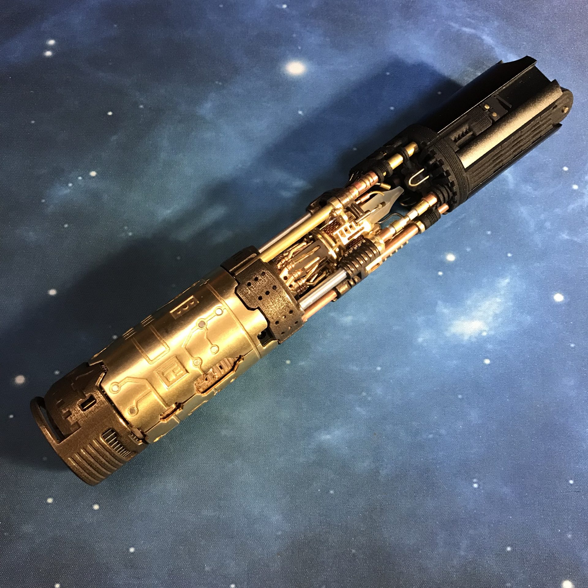
Step 35: Insert the main chassis into the rest of the assembly. There are a few channels for the wires.
/! Important: This part is tricky, first take your time to make the wires fit in properly, making sure no wires are in the way when closing the assembly. You also have to make sure the gear and cycling part rods insert properly into the crystal and Part06 in front, so that both are properly supported and aligned.
Step 36: Lock the assembly using the 1mmOD rods on the both sides. Only a little piece of 1mmOD rod is needed to lock Part12 and Part14 together. Don’t insert them until the end, it is highly recommended to leave some space behind the rods, so it would be possible to push them inside in case it is required to unlock both parts.
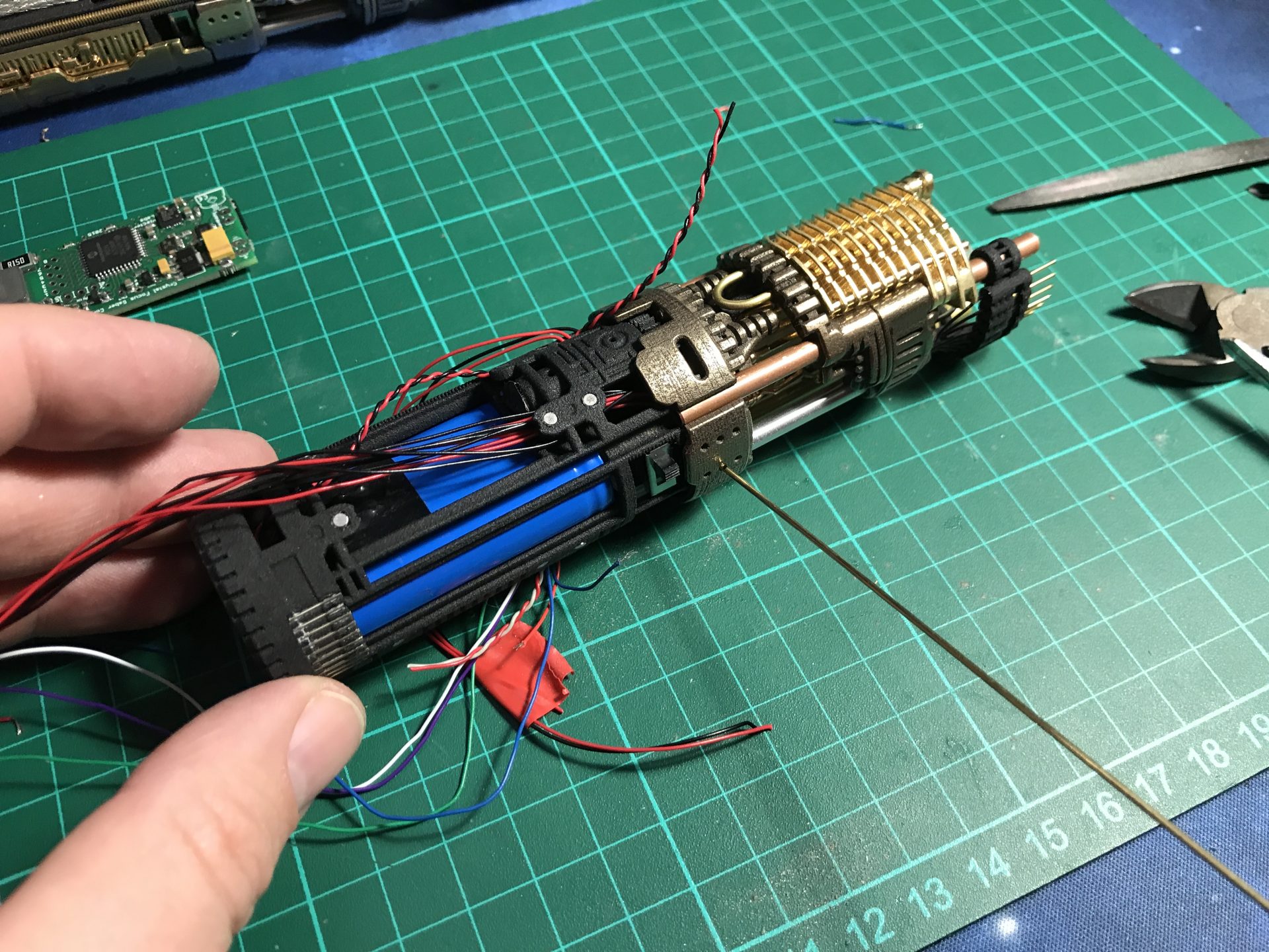
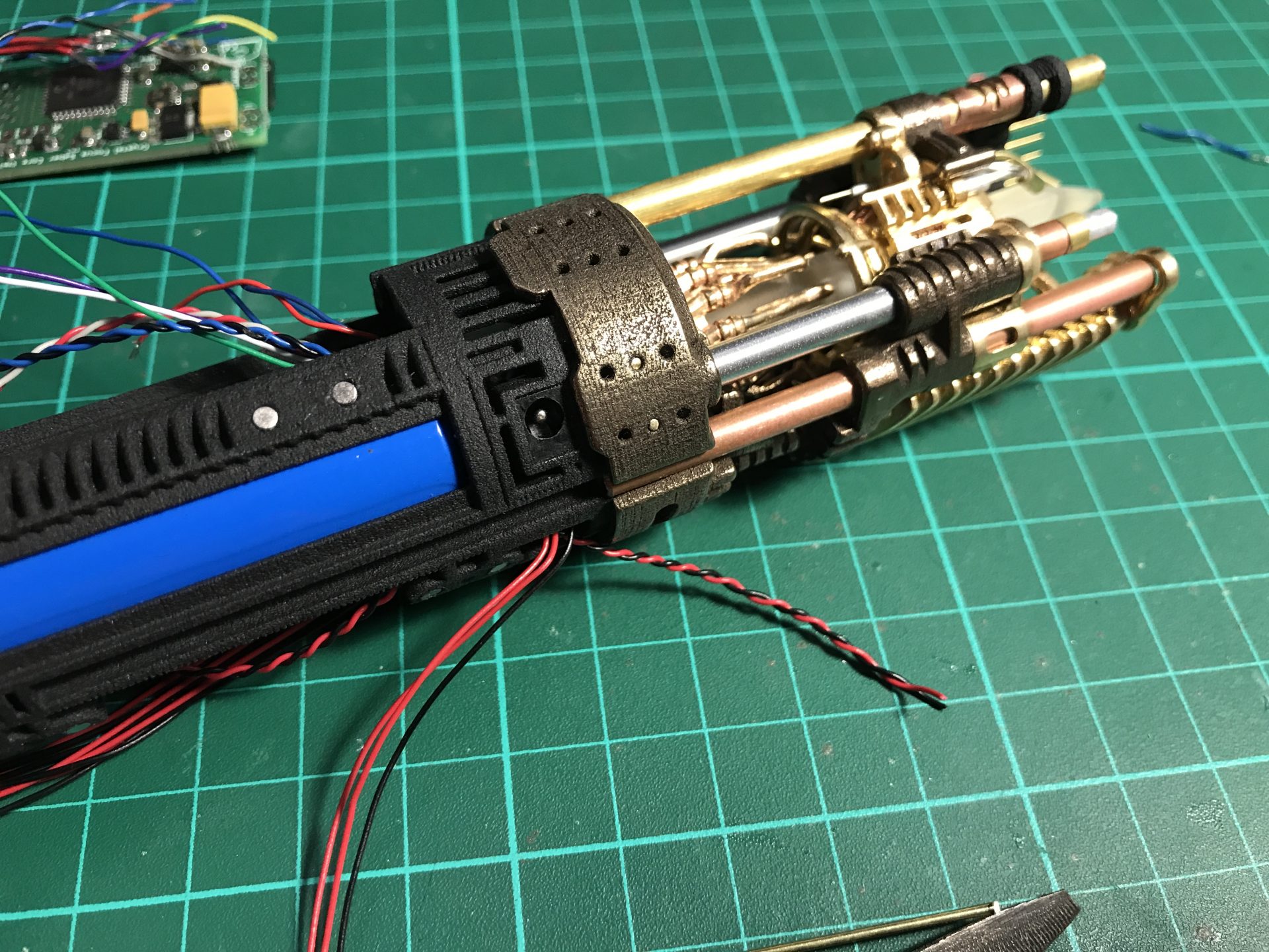
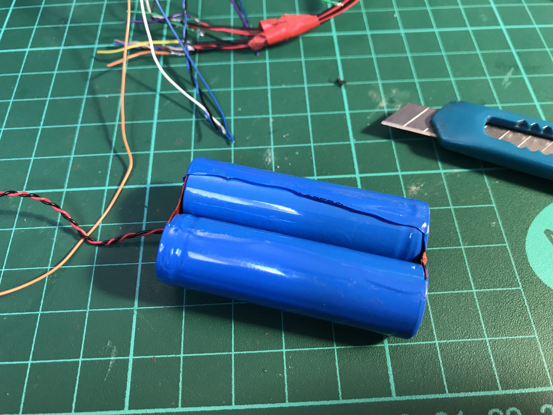
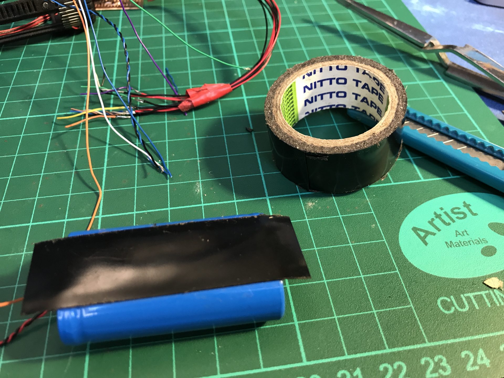
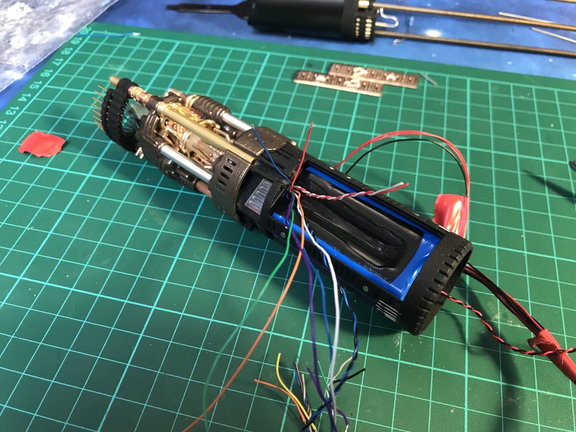
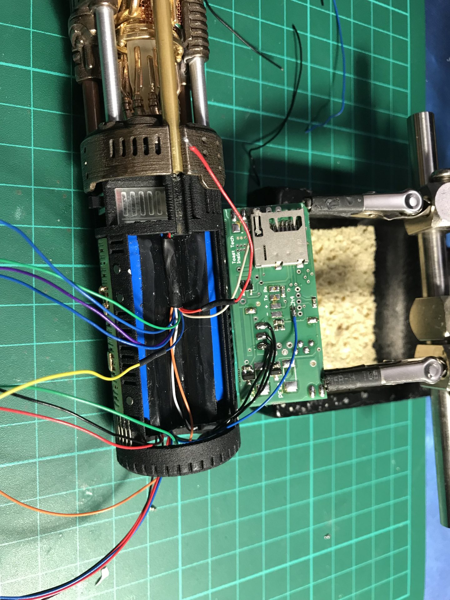
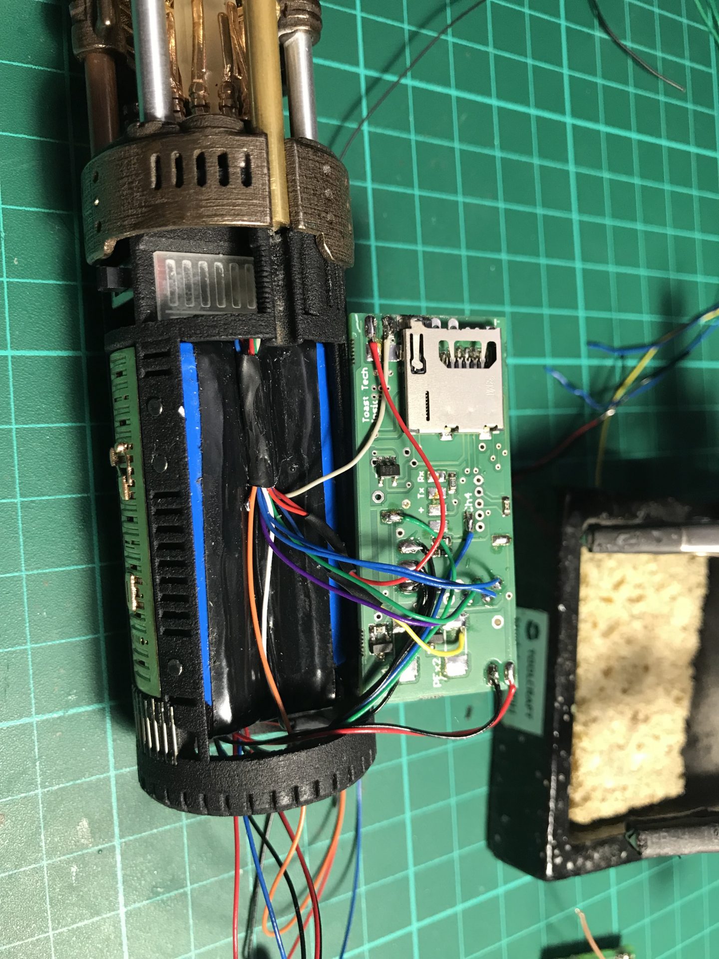
Step37: All empty space counts, as there are many wires. To add the necessary channel space, we open the battery pack heatshrink wrap, which liberates a wires channel and protect it again with Nitto tape that shrinks and takes the form of the battery.
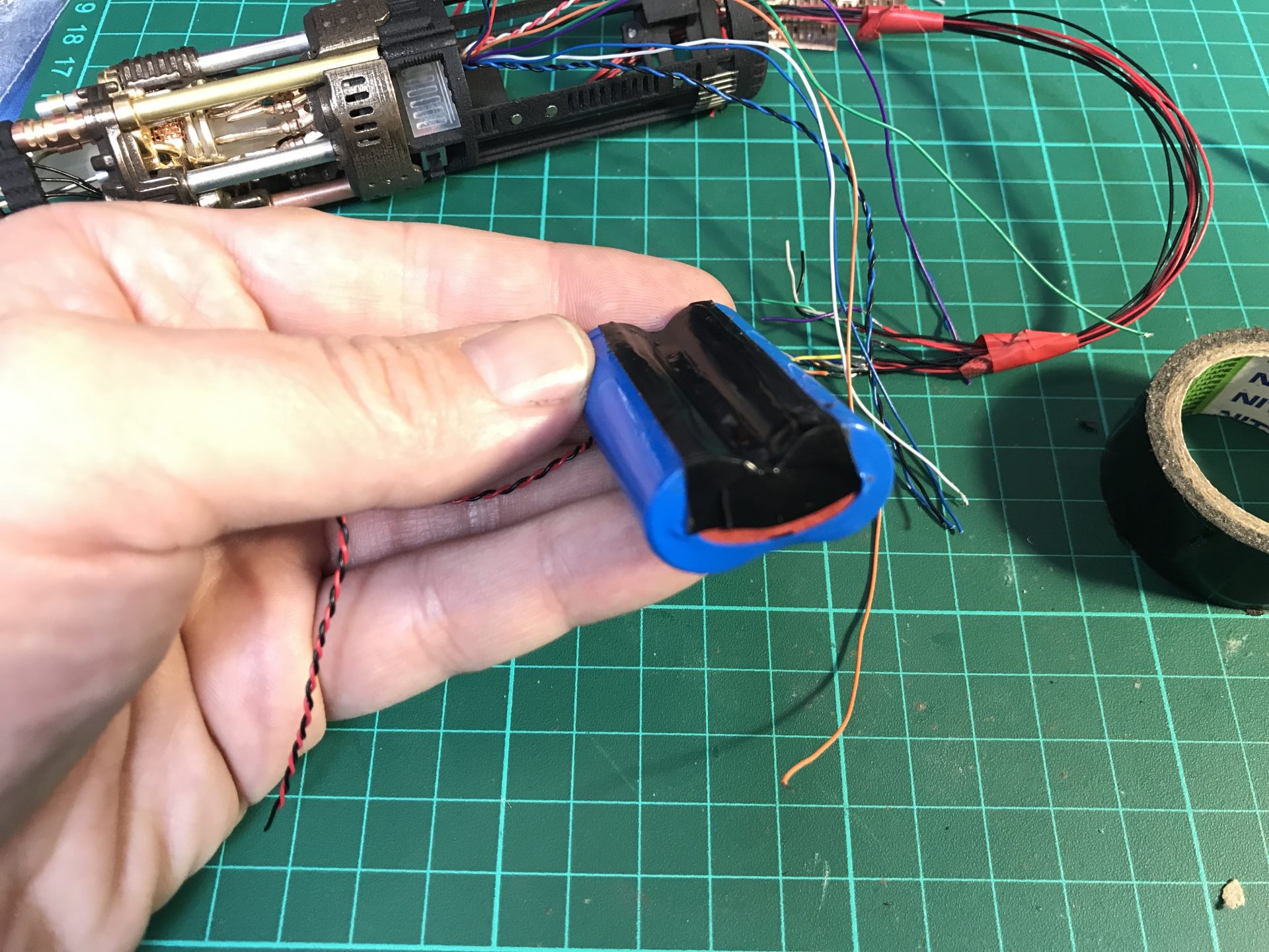
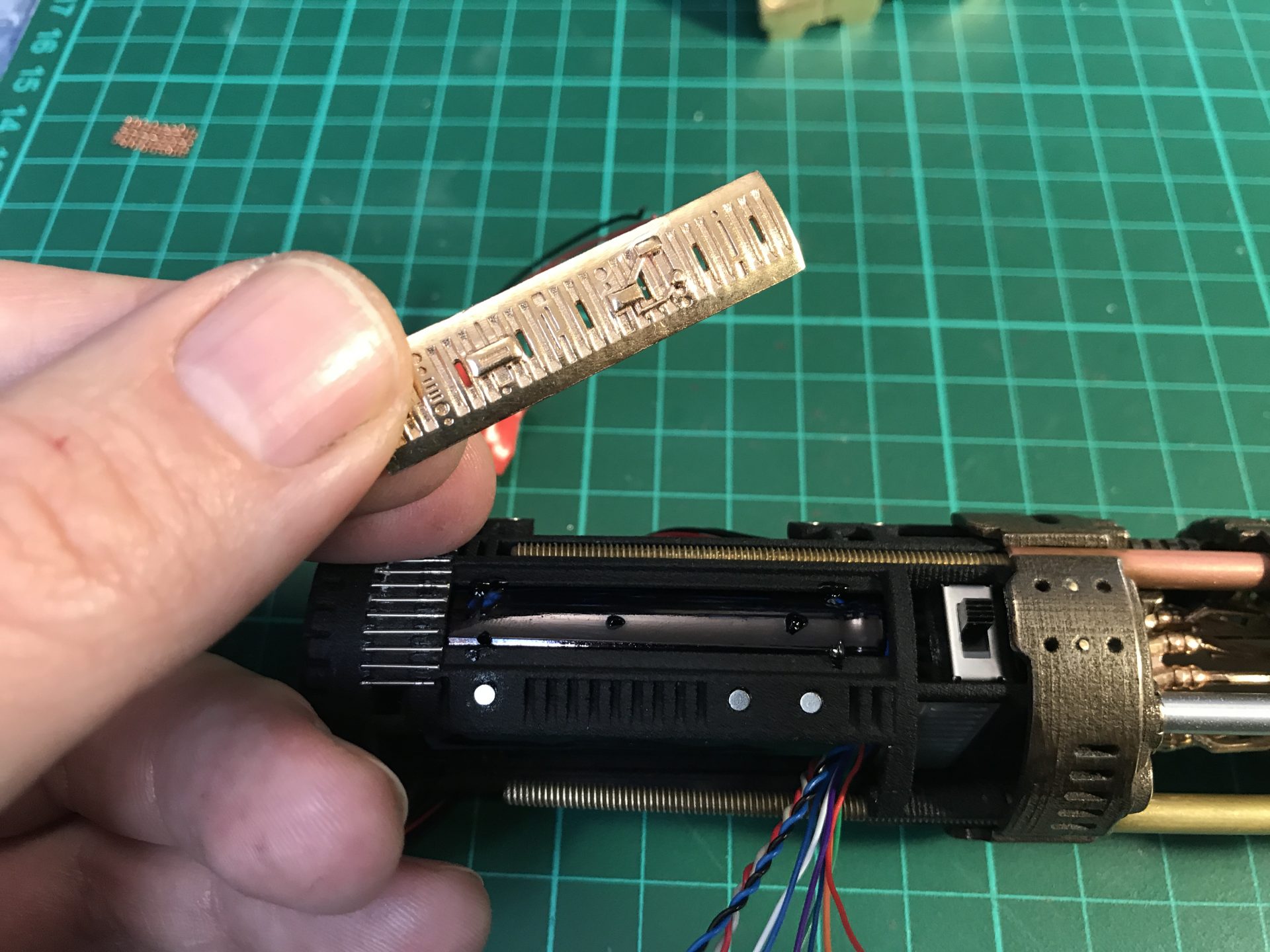
Step 38: make sure no wires are caught in the way and insert the battery.
Step 39: Glue the side plates on both side, respecting the right orientation.
Step 40: Solder the Color Extender wires (on the side) and insert it.
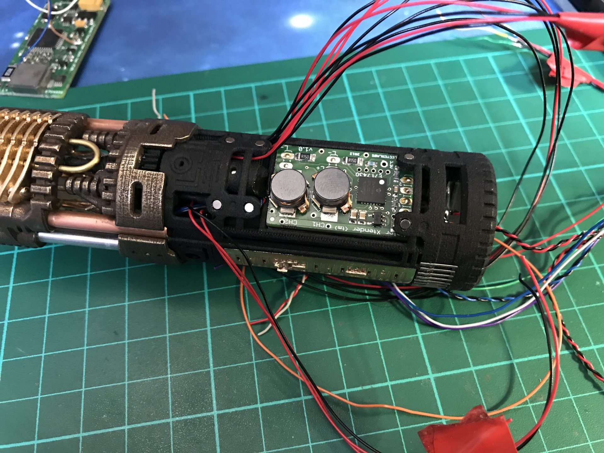
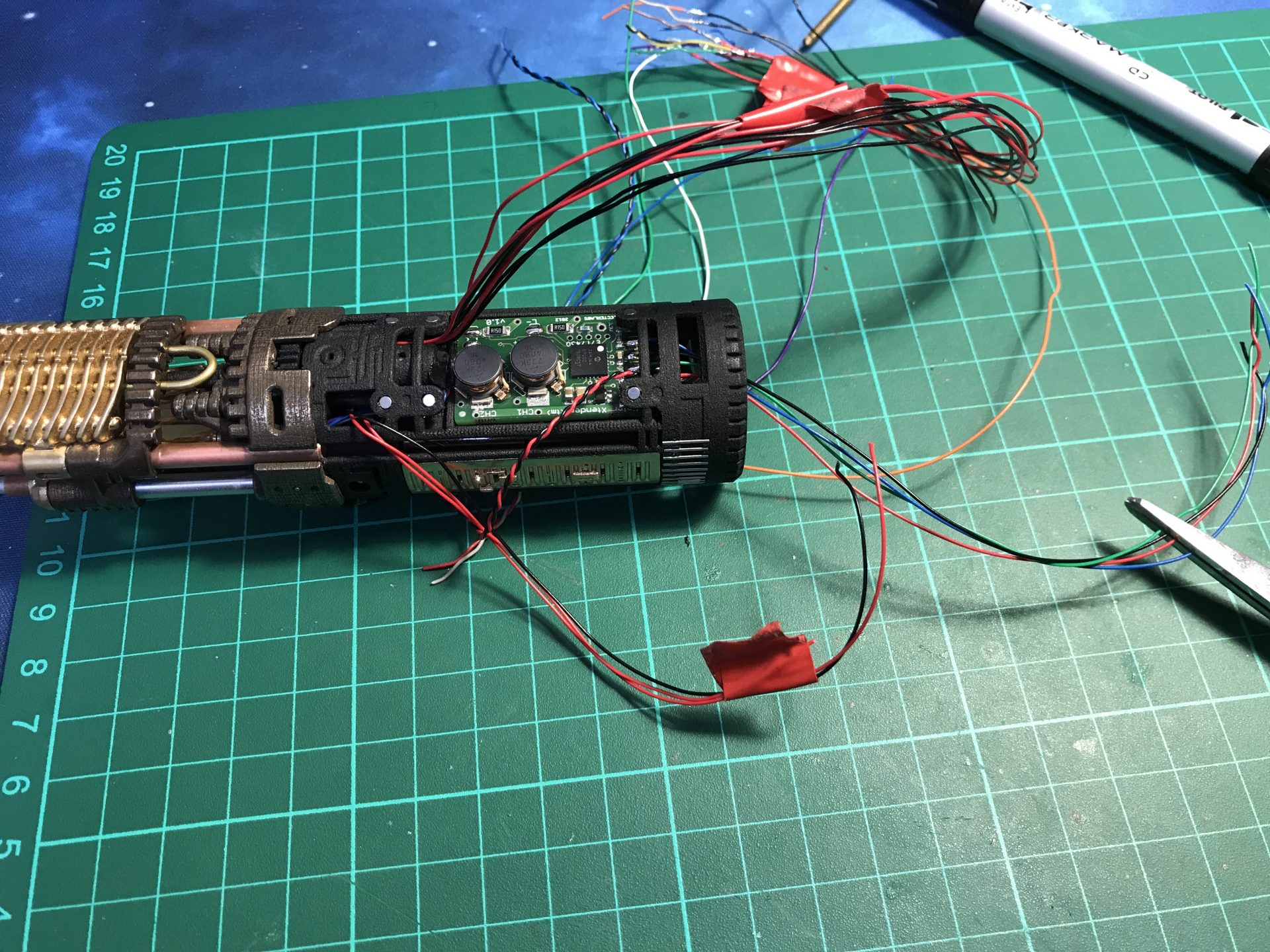
You are free to install your wires as you prefer. To make it look good, we have protected the board with Nitto Tape (heatshink) and passed the wires through a 3mmOD tube as shown below:
Step 41: Add the blue and red 3mm accent leds. You can also add other cosmetics elements to hide the wires, like mesh to close open sections.
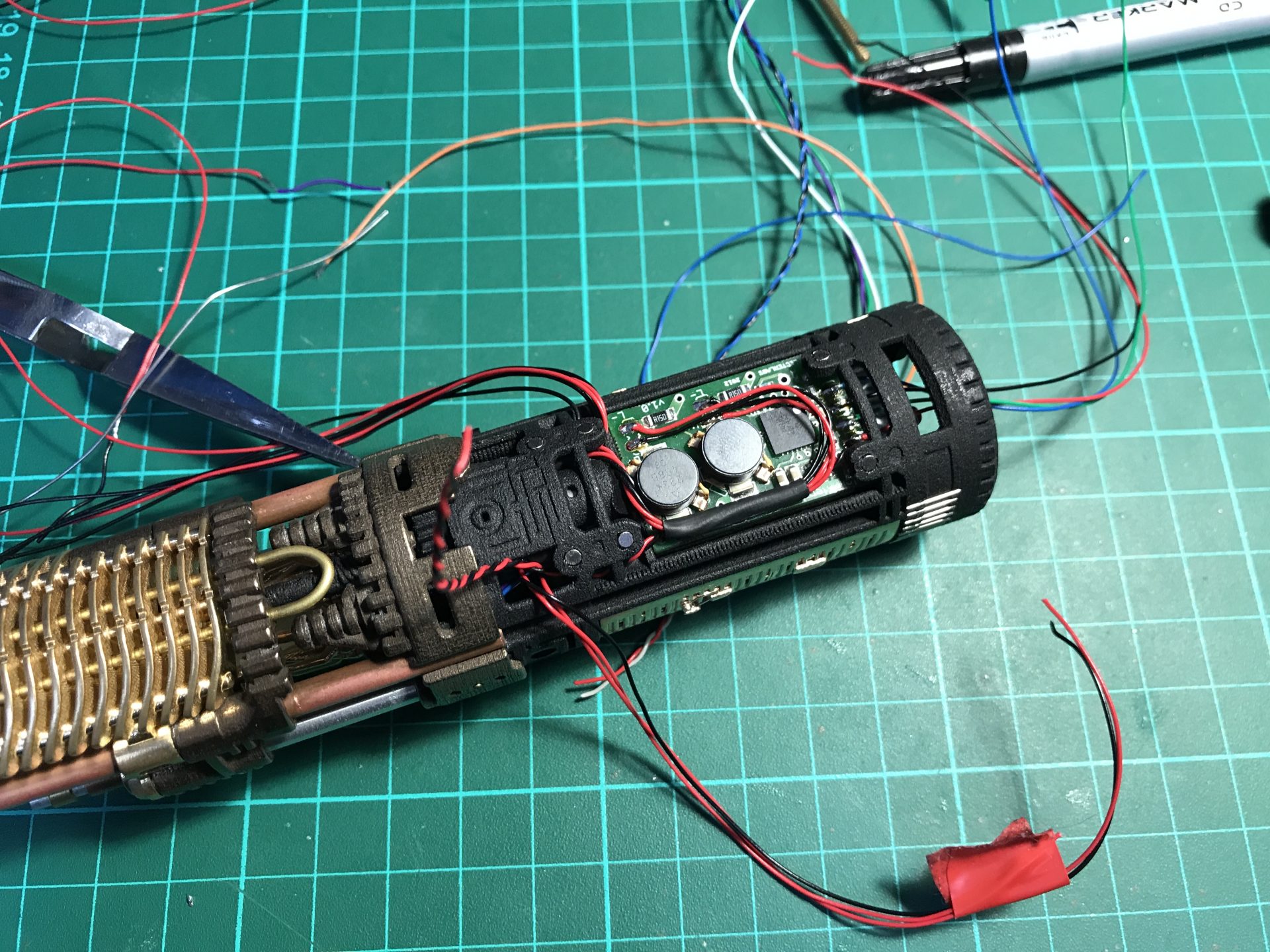
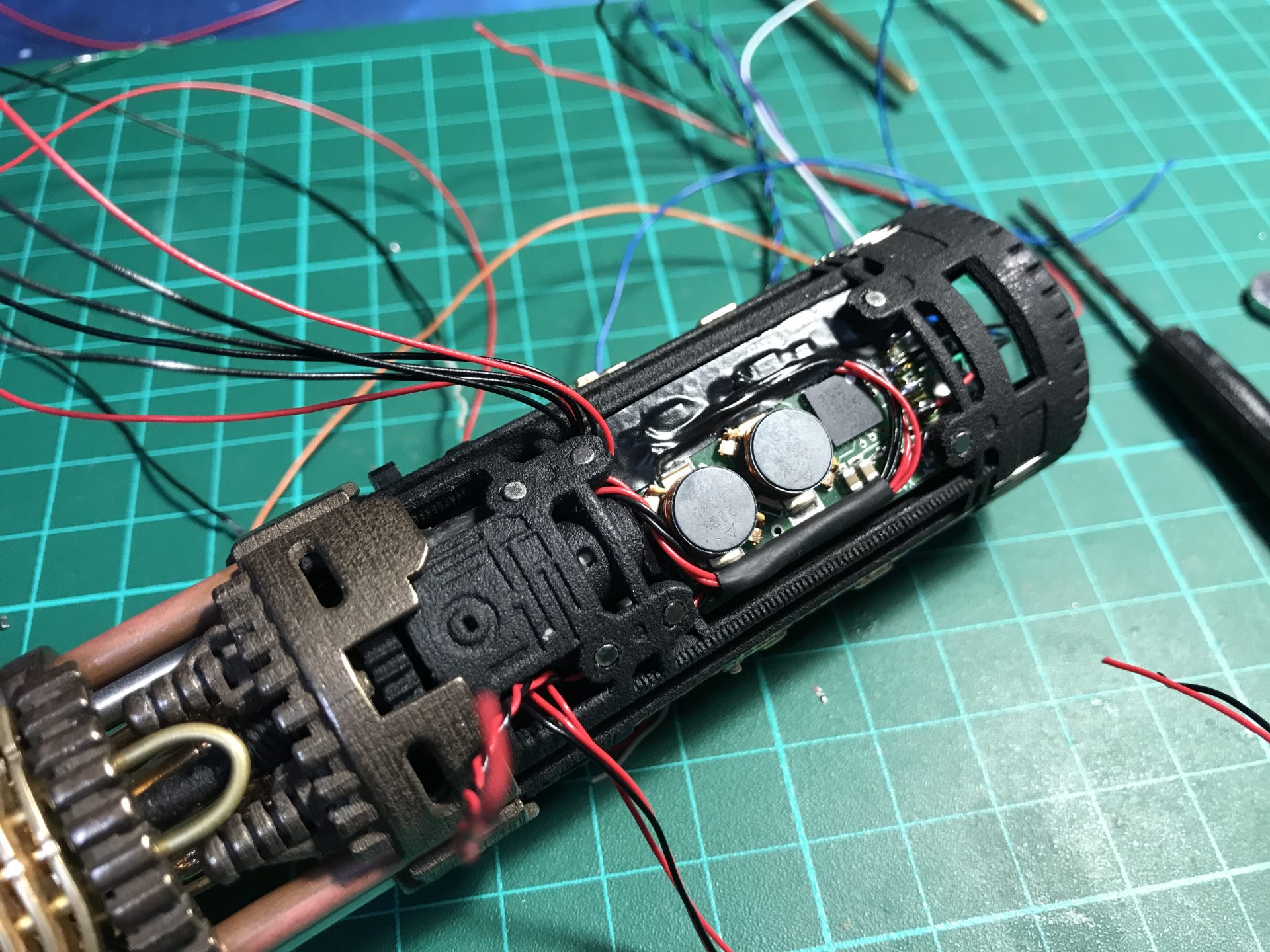
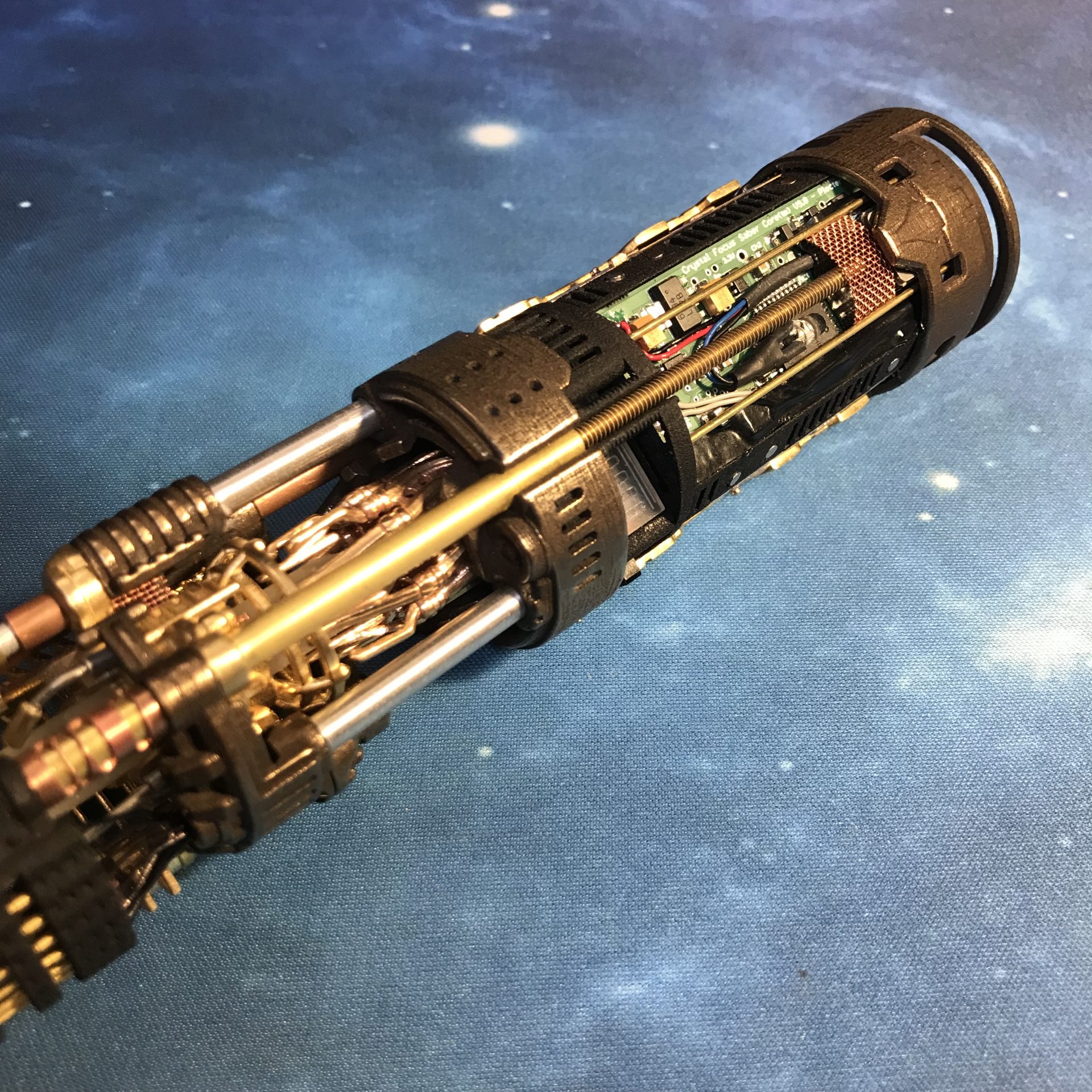
Step 42: Install the CF9 (make sure your accent led pads are prepared with led resistors or bridge – see CF9 manual). First solder the wires on the back.
Then once inserted in the chassis (make sure it stay flat and secured), you can pass the remaining wires on the side of the big led driver.

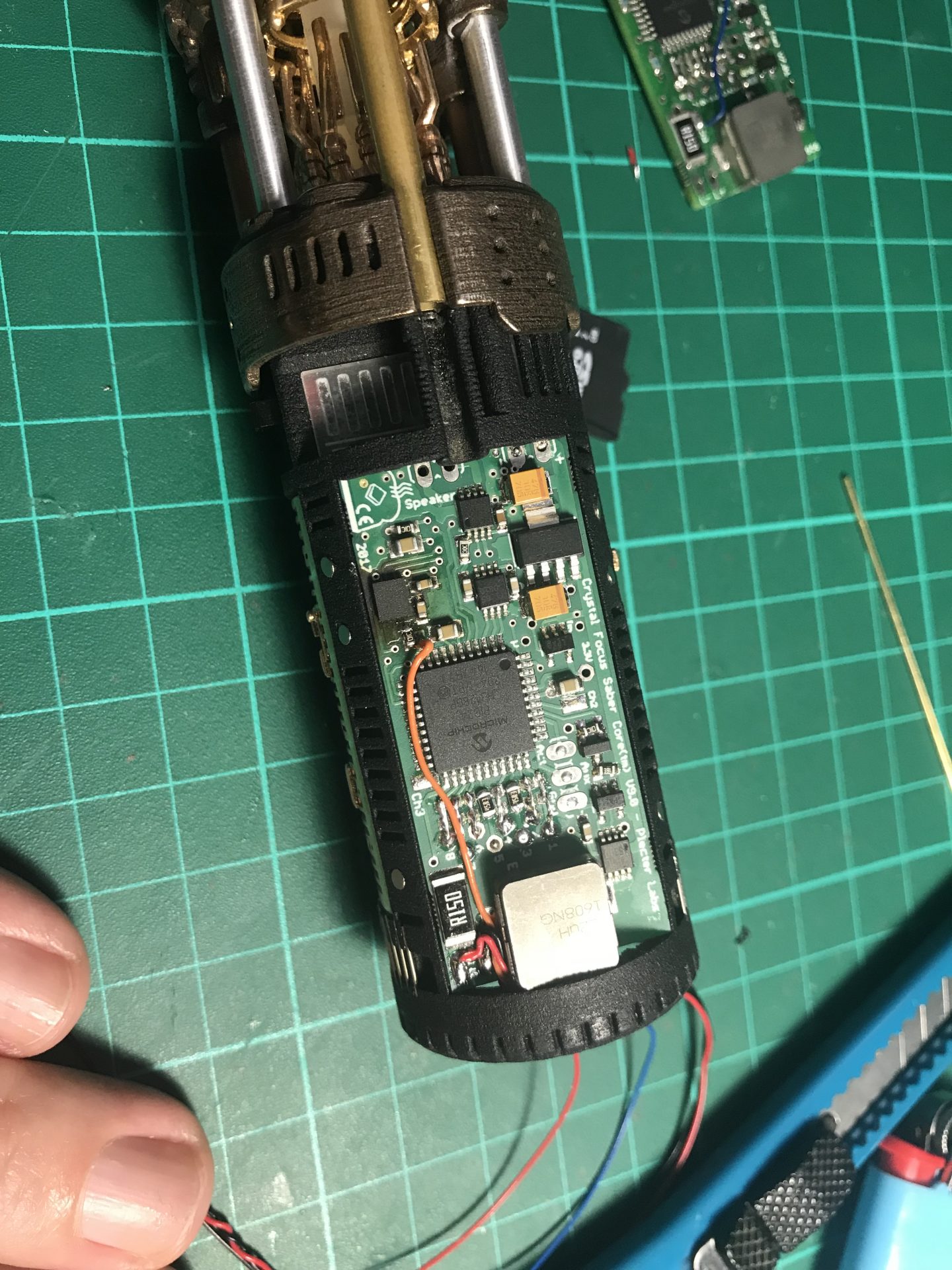
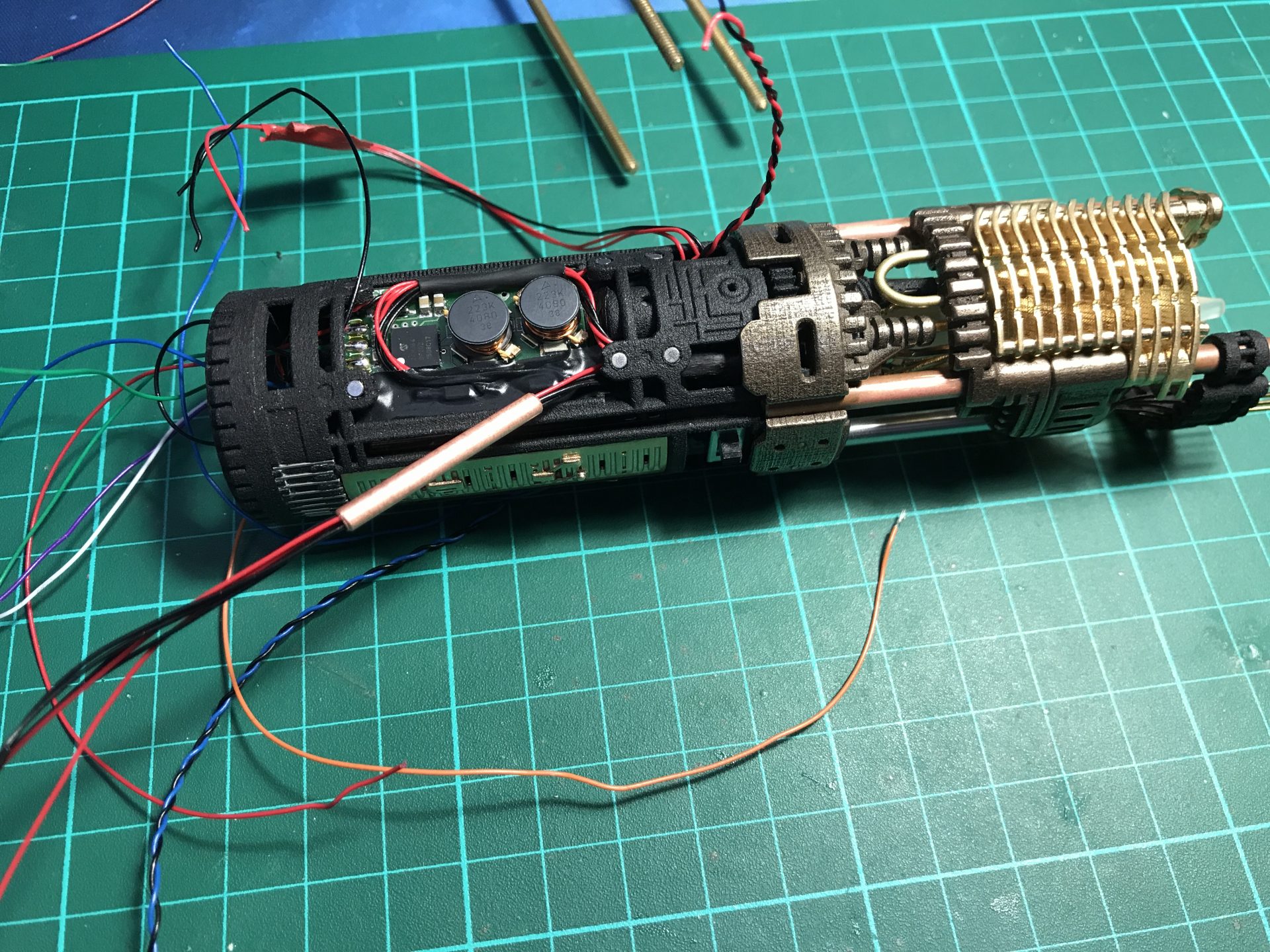
Make sure no wires get in the way of the threaded rod. Then you add two Rods 5) as cosmetic.
Step 43: Install the flat 28mm speaker. Then solder the last accent led to be glued aside of the 4-40 rod.
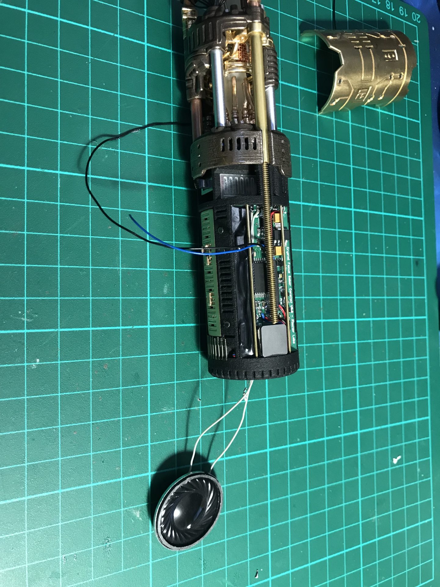
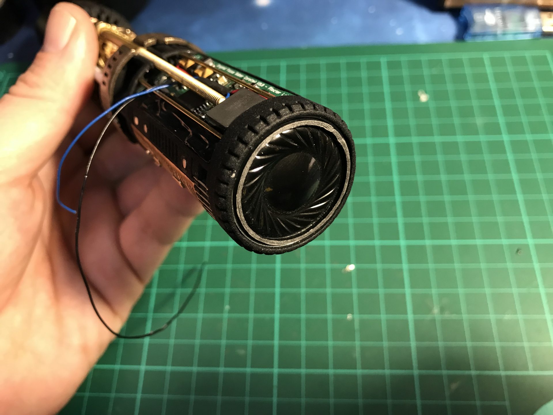
You can also add a mesh to the speaker cap for a better look!
Step 44: Install your grips on the Graflex bottom.
/! Important: no grip screws or rivets can protube inside the bottom tube or it will block the chassis. Wheter you drill or not the tube, make sure the length of you screws/rivets is set accordingly.
(even on a vintage install, we keep the vintage bottom untouched to keep the original flash look, and use a replica bottoms for lightsaber look according to the style chosen ANH, ESB or TFA/TLJ).
Step 45: Add sound and ring holes to you graflex bottom. Then install your D-ring or Kobolt with rivets or screws.

Step 46: Add the chassis spacer ring to the bottom of the graflex tube. This secure the chassis once the graflex is fully assembled (this is just to prevent chassis extension when making very strong swings, so totally optional if the hilt is display only)
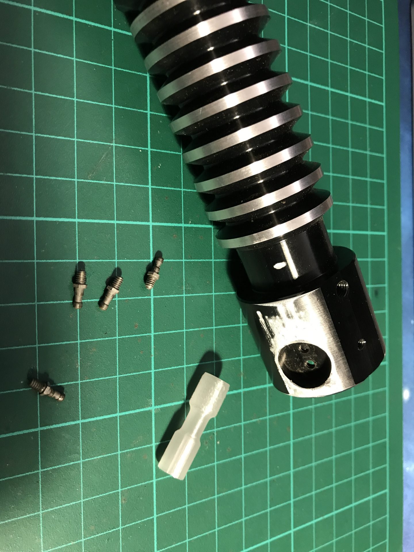
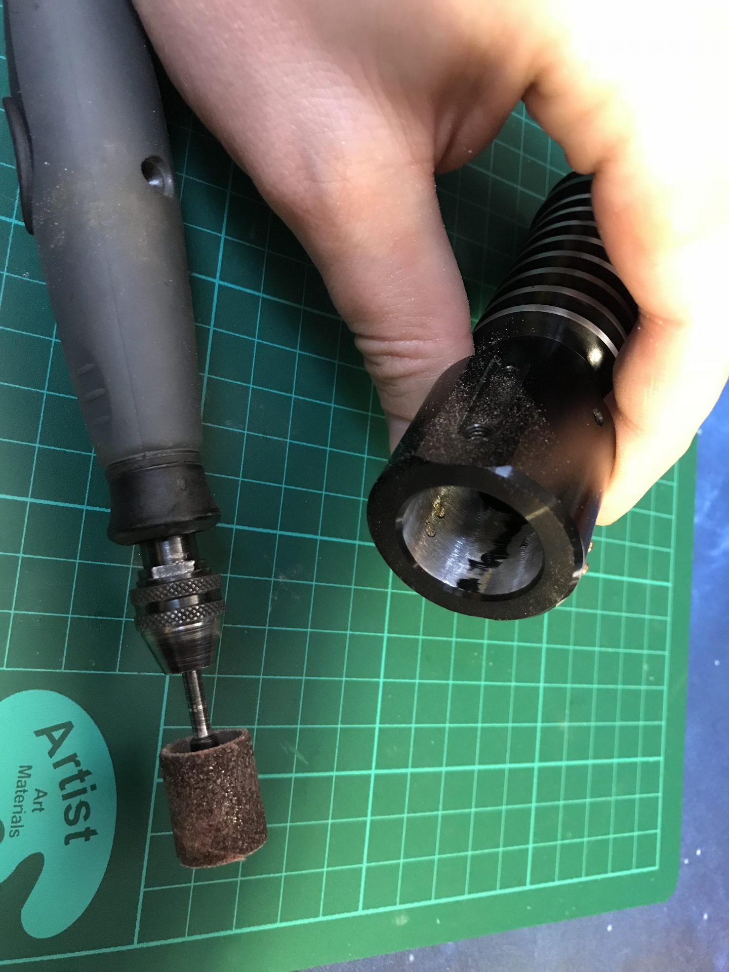
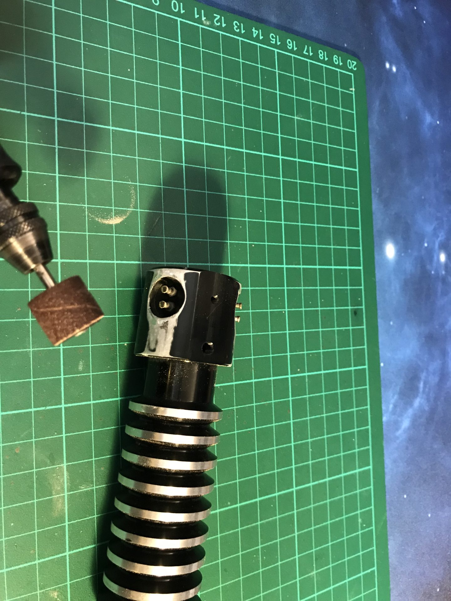
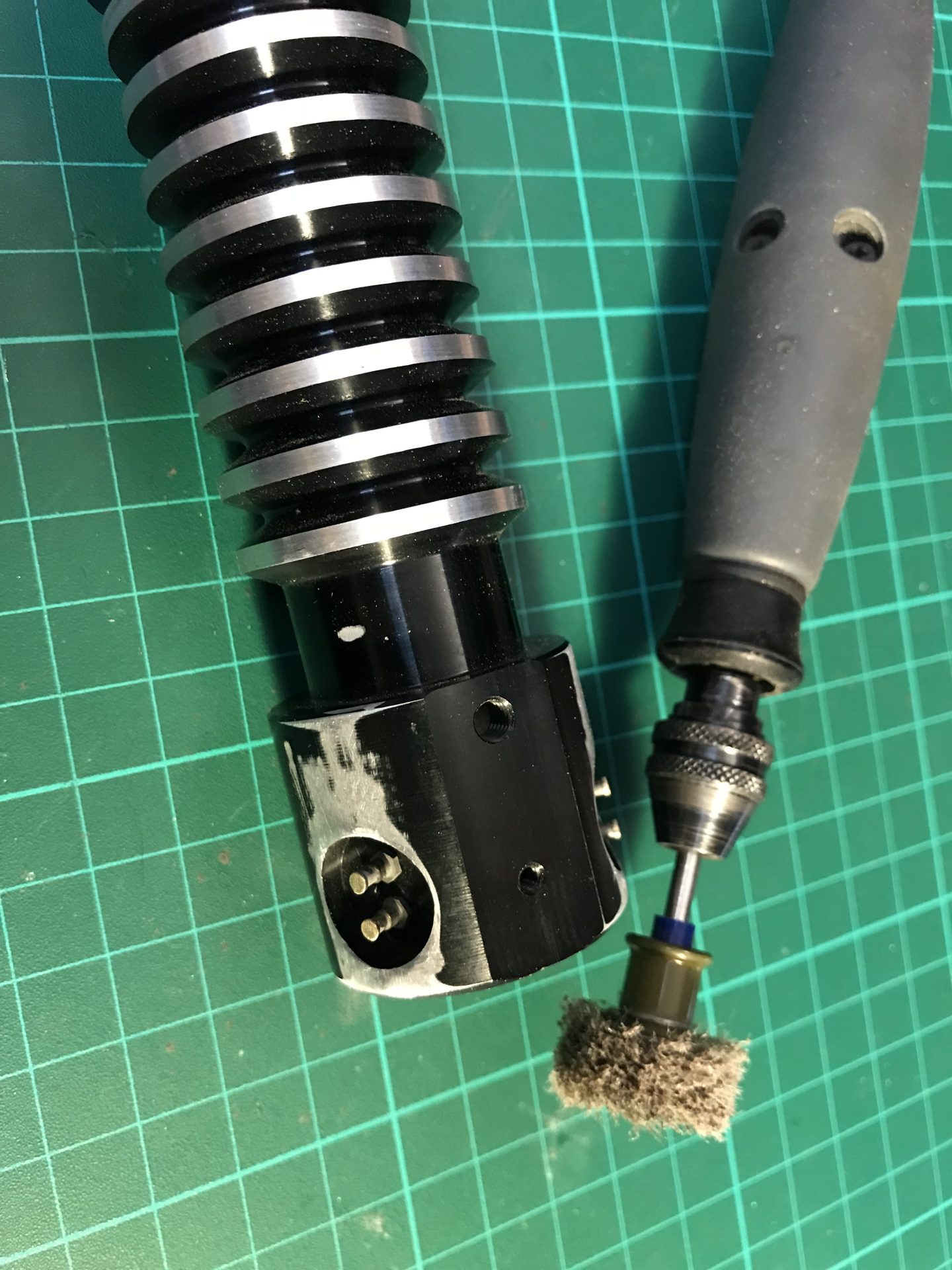
Step 47: (optional) If you want to have a full core reveal (meaning including the blade holder with TGS, KR or NerfworXlab holders, and not just the extendable chassis), you will have to sand down you brass pins. For this we used a Graflex 2.0 spare blade holder and Dremel.
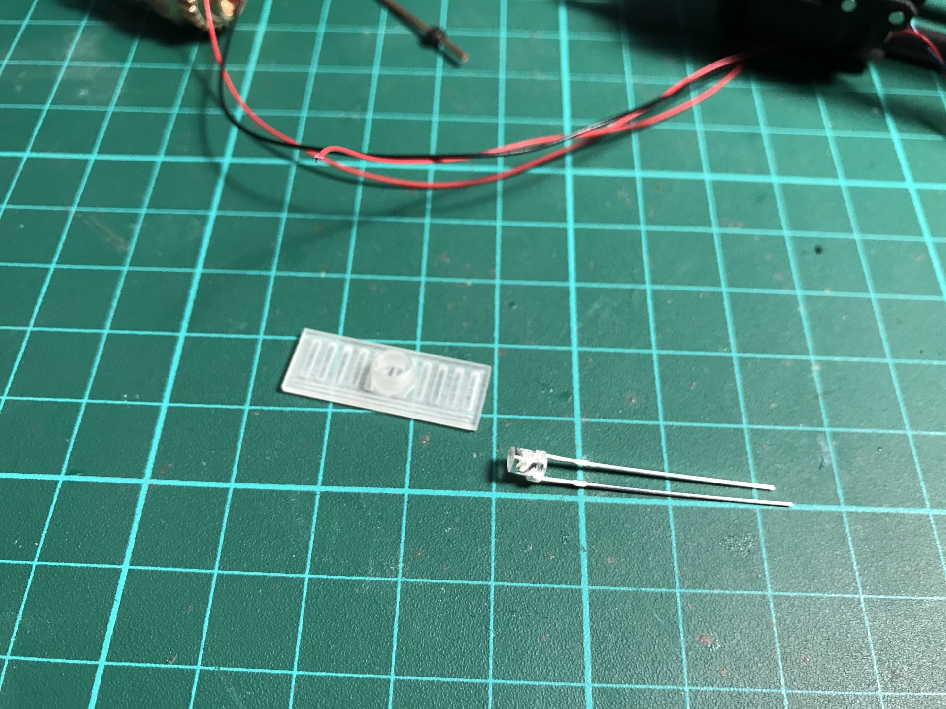
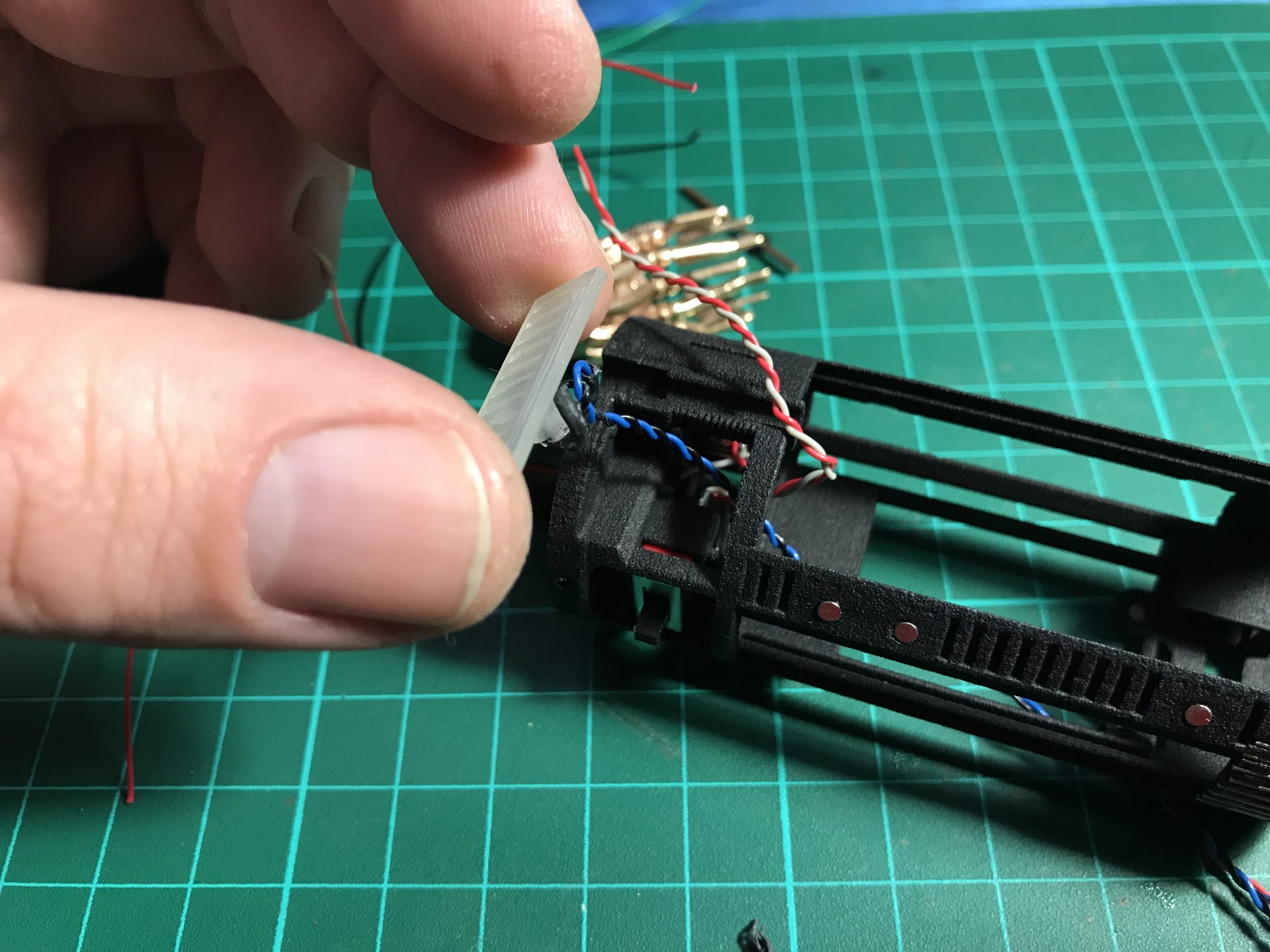
Step 48: Glue a plastic piece under the switch to make it able to activate the main switch on the blade holder.