These designs are no longer supported (FAQ)
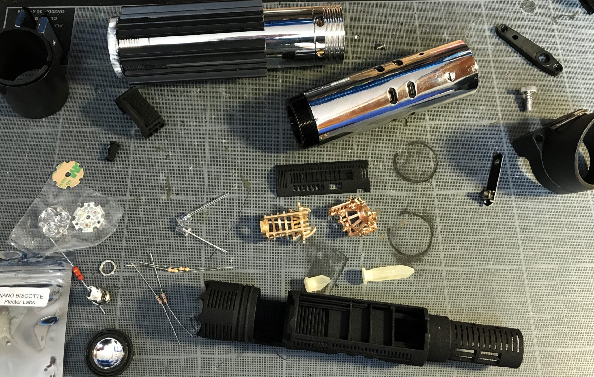
Parts Details:
For Korbanth new MPP2.5 (2019) => go to this page.
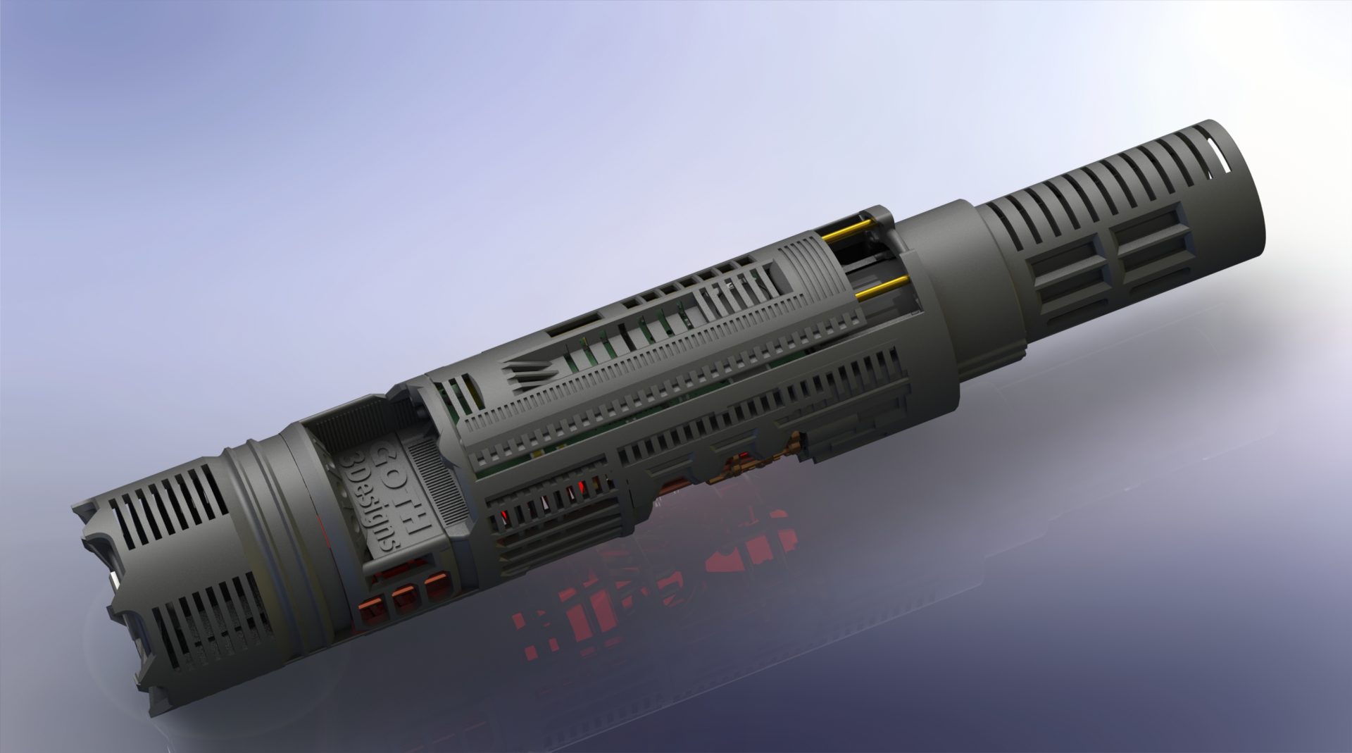
Sith Master Chassis:

⇒ Part 1 – Main chassis – 3 items (Plastic – recommended in Black): mpp2-0-sith-master-chassis-part1-main-chassis
⇒ Part 2 – CC insert 1 (Plastic / Metal – recommended in raw brass/bronze): mpp2-0-sith-master-chassis-part2-ccinsert1
⇒ Part 3 – CC insert 2 (Plastic / Metal – recommended in raw brass/bronze): mpp2-0-sith-master-chassis-part3-ccinsert2
⇒ Part 4 – optional 2 crystals: mpp2-0-sith-master-chassis-part4-crystals
DEMO
DIY INSTRUCTIONS:
Disclainer:
– These instructions will details the install procedure as much as possible. GOTH-3Designs cannot be held responsible for any mistakes made by DIYers.
– Always wear protective gear when working on install (gloves, eye protection, …), GOTH-3Designs cannot be held responsible in case of accident.
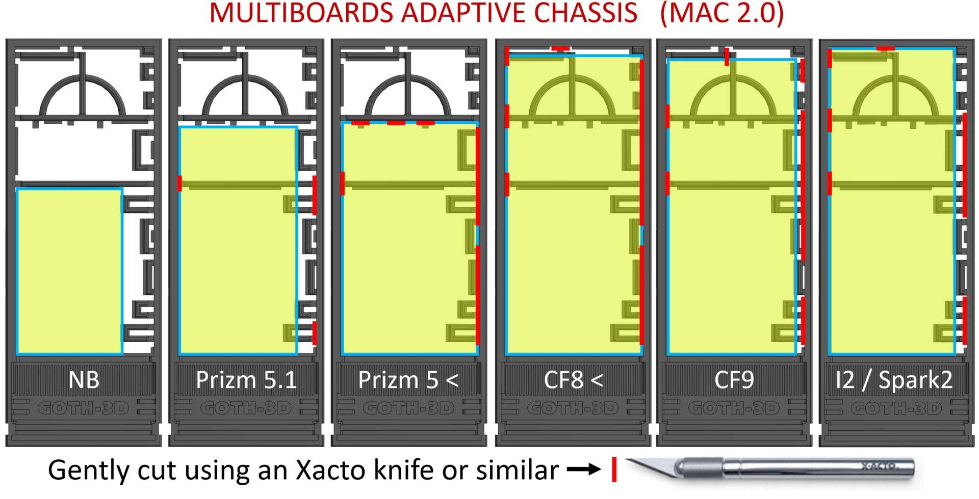
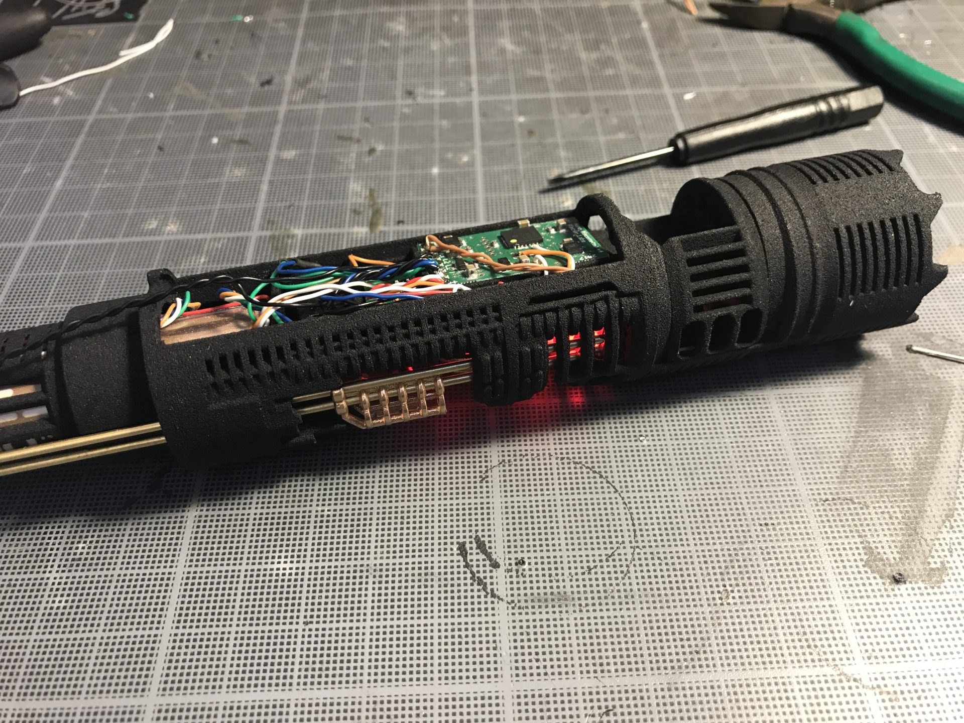
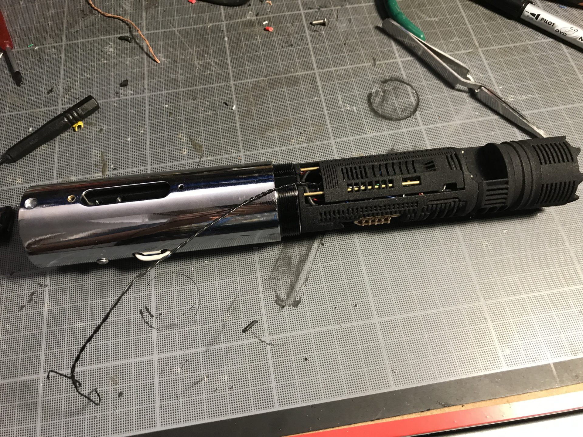
MULTIBOARDS ADAPTIVE CHASSIS
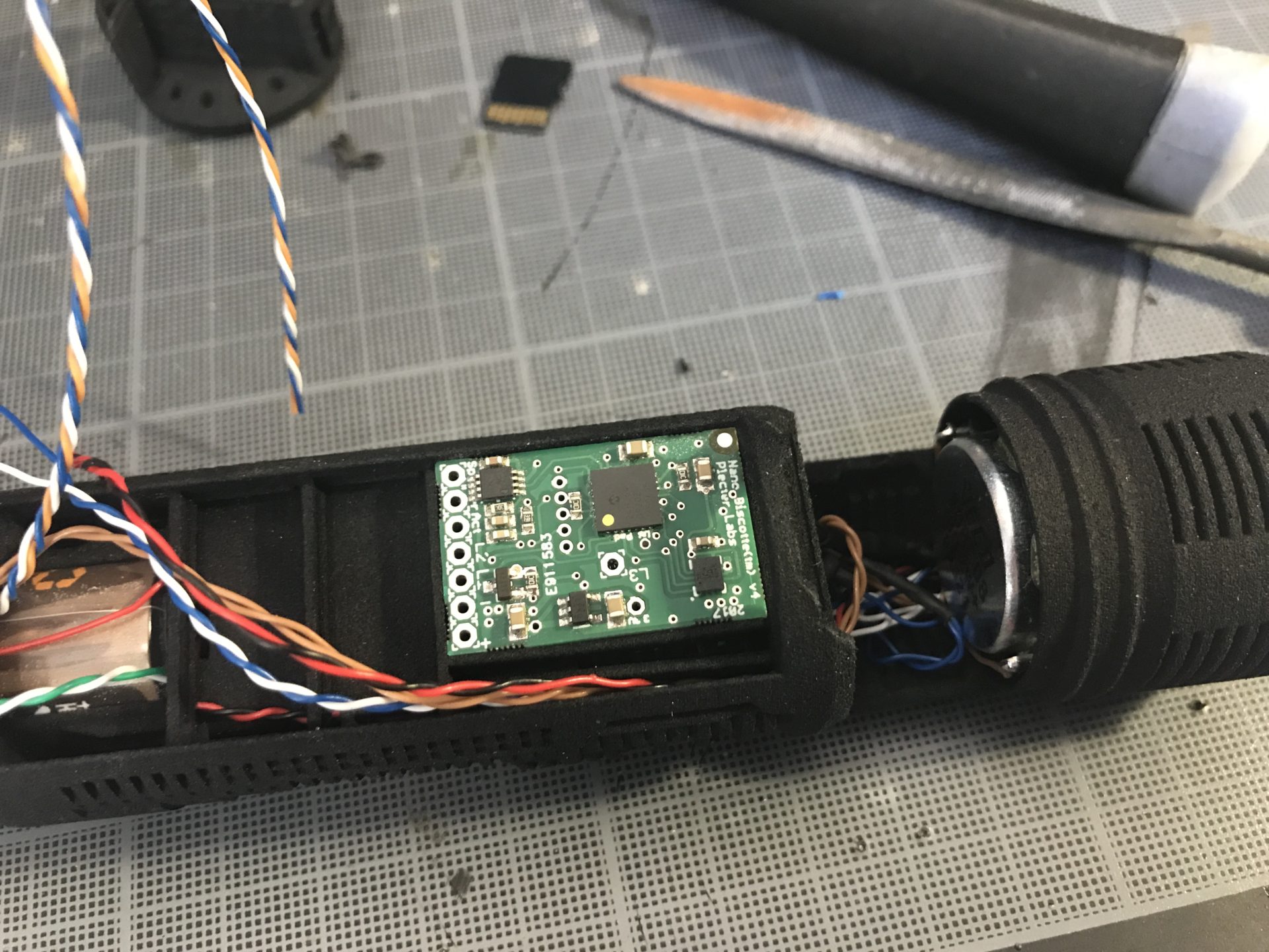
On the Sith Master Chassis, install the soundboard with the SD card on the bottom, facing the pommel. The cut pattern is thus the similar as below, just inverted.
Note 1: Please read these instructions fully before starting.
Note 2: These instruction will cover the Nano Biscotte 4 install, however the MultiBoards Adaptive Chassis will allow other soundboards to be installed. We do not cover wiring instructions tho, please read your soundboard manual before starting the install.
Note 3: 30awg wires and smaller are mandatory for this install (30awg for main wires and 32awg for accent leds and switches are highly recommended).
Note 4: These instructions will details the install as much as possible. GOTH-3Designs cannot be held responsible for any mistakes made by DIYers tho. Thanks to read the full instructions before starting your install. Commission an installer to build the hilt for you, if you feel unsure about what to do.
Note 5: You can always make your chassis original by painting it or adding metal mesh.
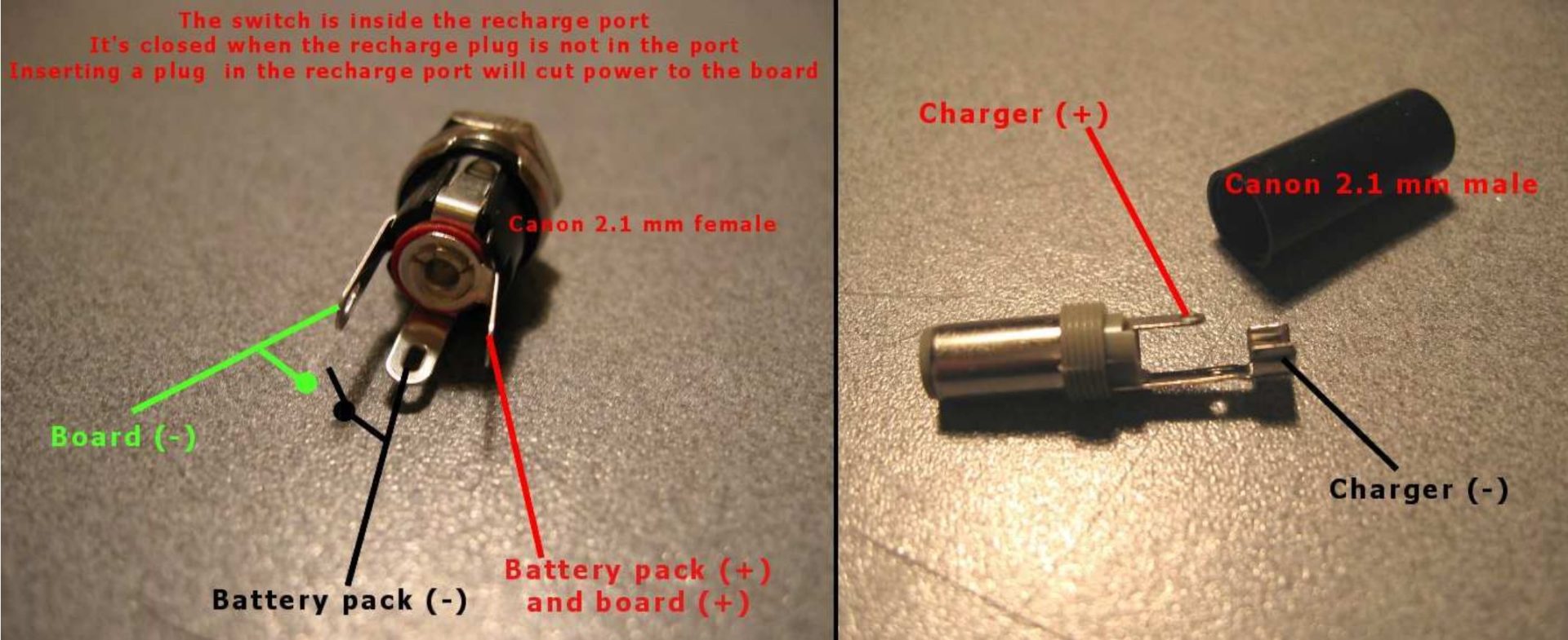
Note 6: Recharge Port wiring reminder
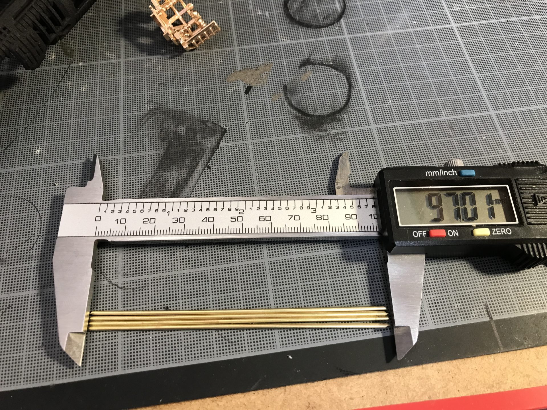
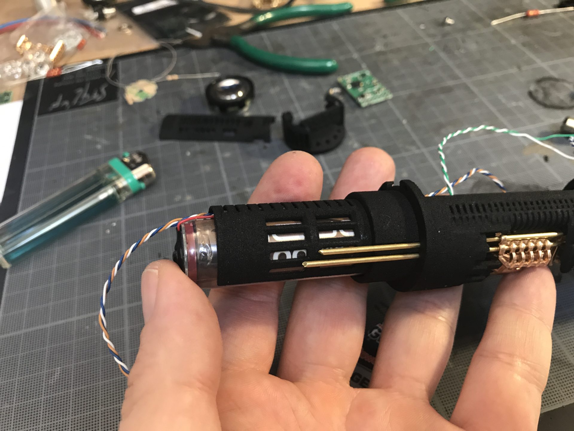
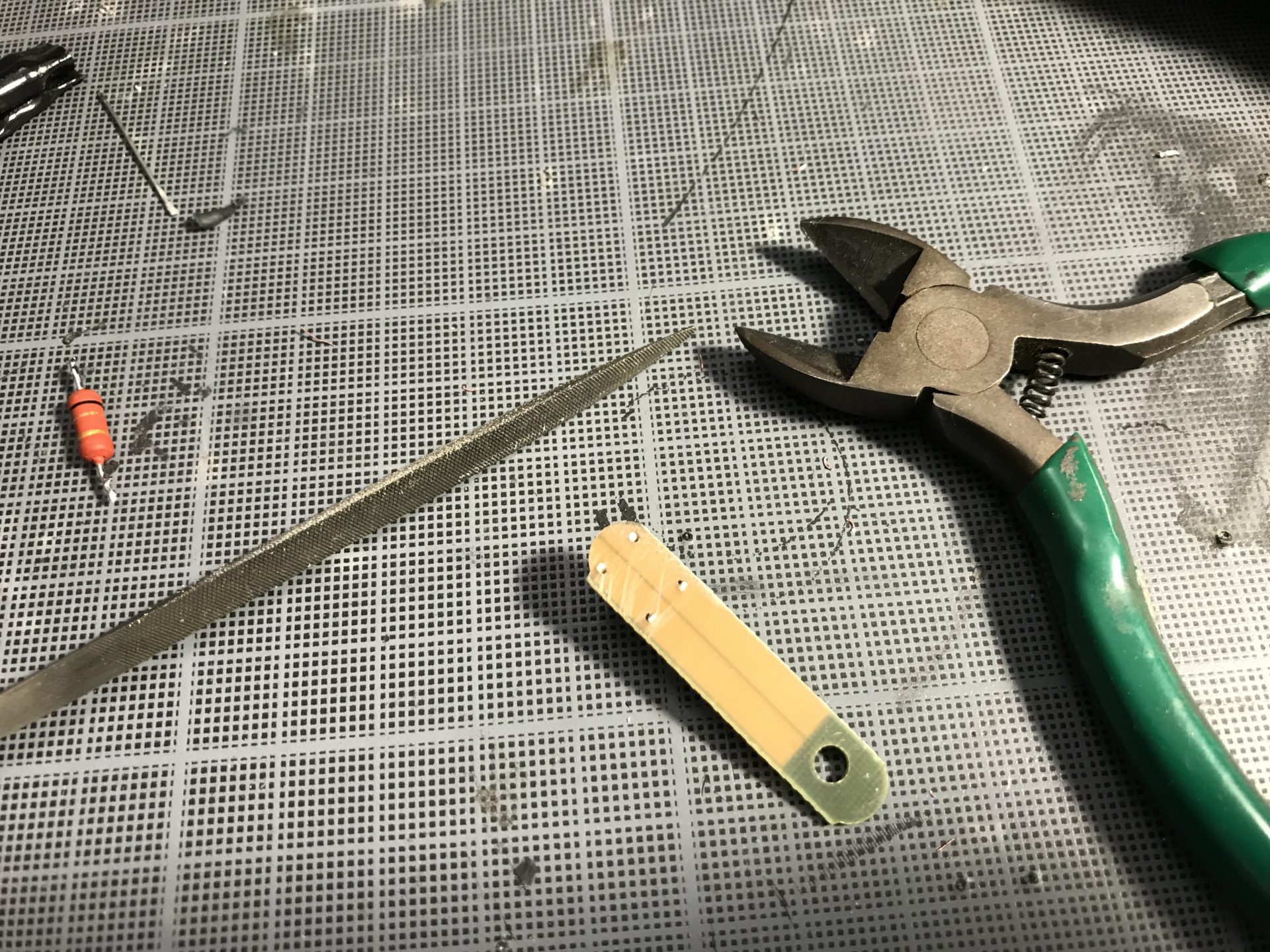
Step 1: Cut the 1.5mm OD rods (4) to the right length (approx 96mm is fine), they will support the crystal chamber inserts
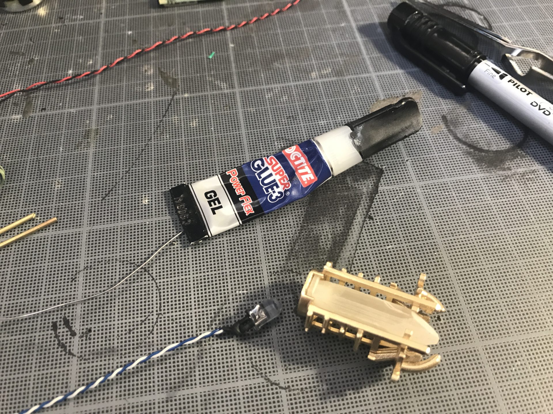
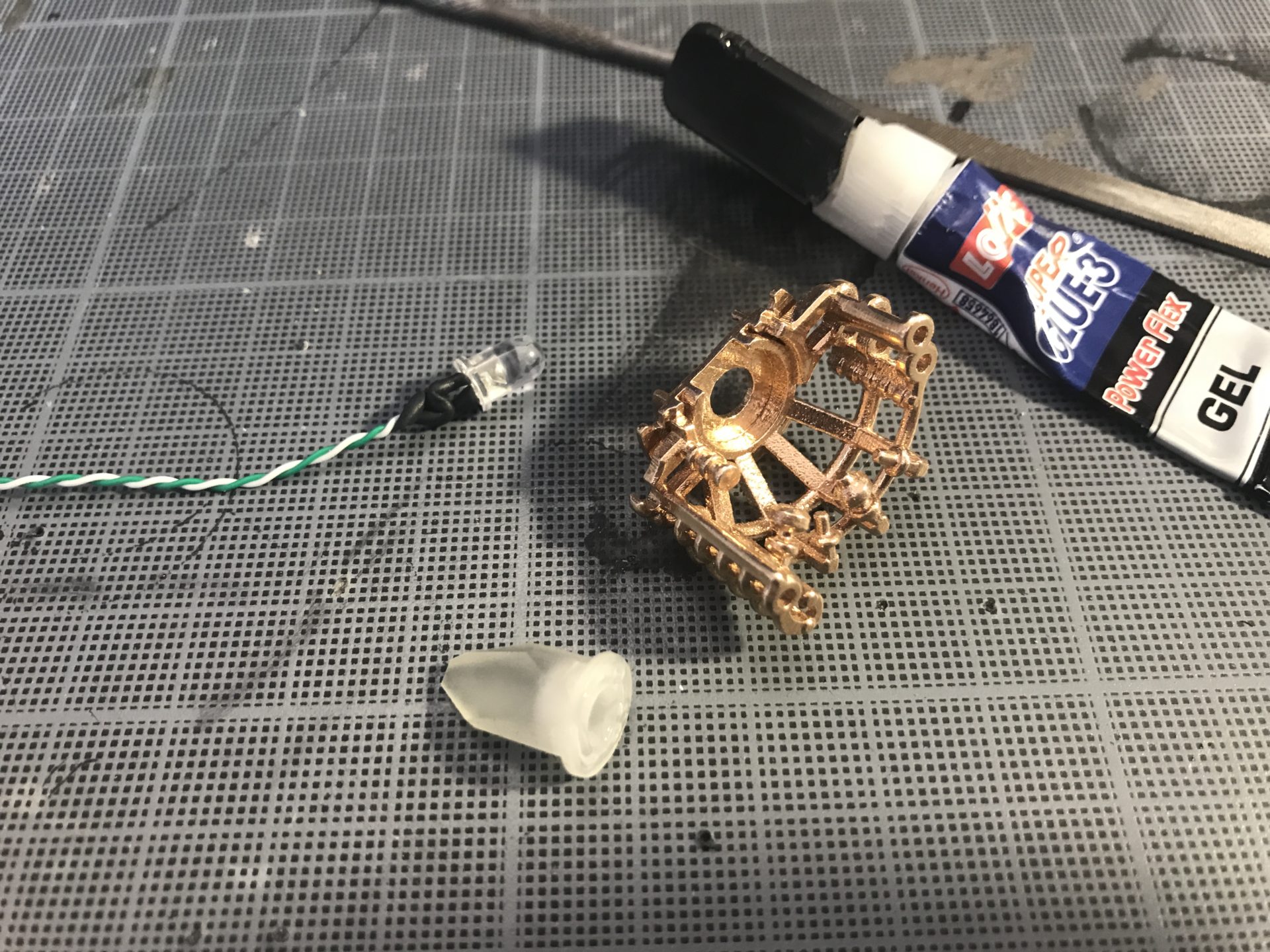
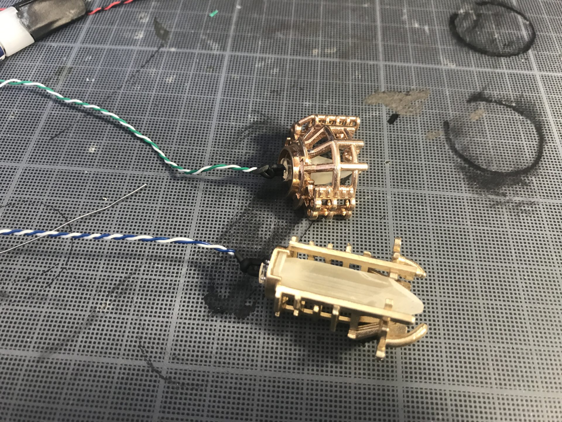
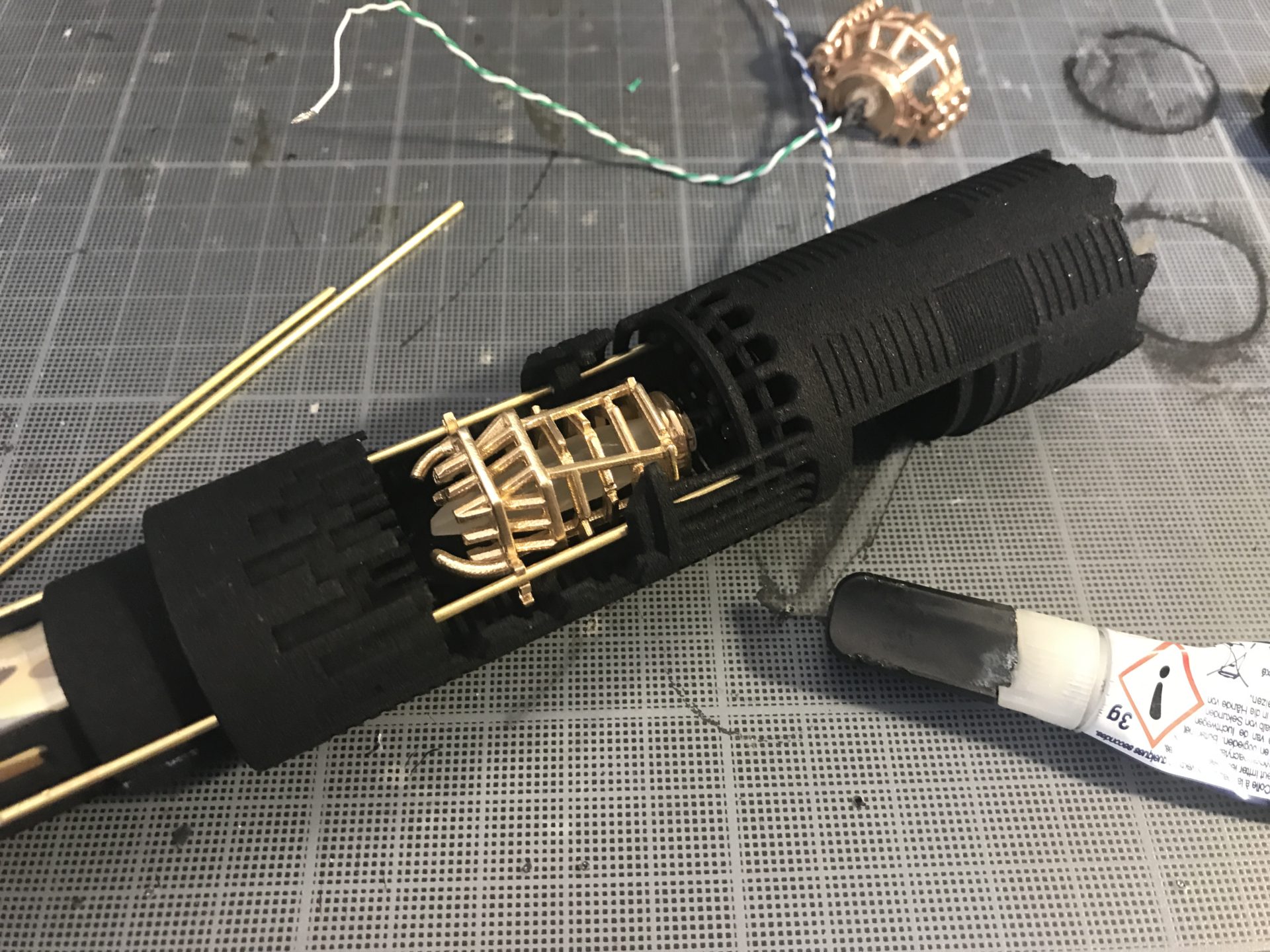
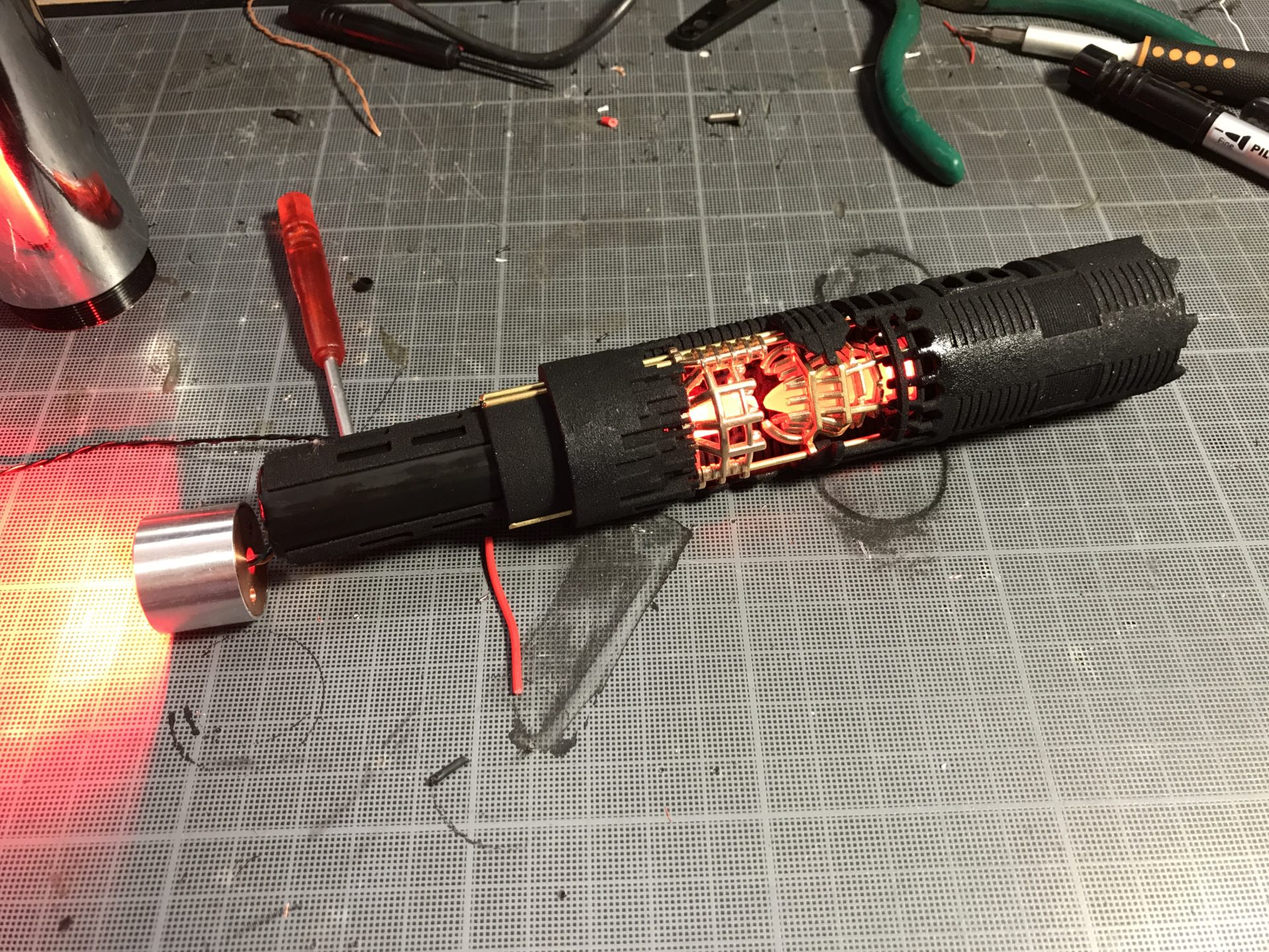
Step 2: Prepare you crystal chamber inserts 1 and 2, with there 5mm accent leds. If using the 3D printed optional crystal, they should press fit into the CC insert (some light sanding of the round base might be required). It is better to glue the crystal with a bit of super glue to secure them on the CC inserts. The 5mm led doesn’t need to be glued however as it will insert and stay fit in the crystal.
Step 3: CC insert 2 must de place first into the chassis. Then use the 1.5mm as guide to glue it (glue the round part on the back of the insert with a bit of super glue, then hold in place until it is secured. You can remove the rods.
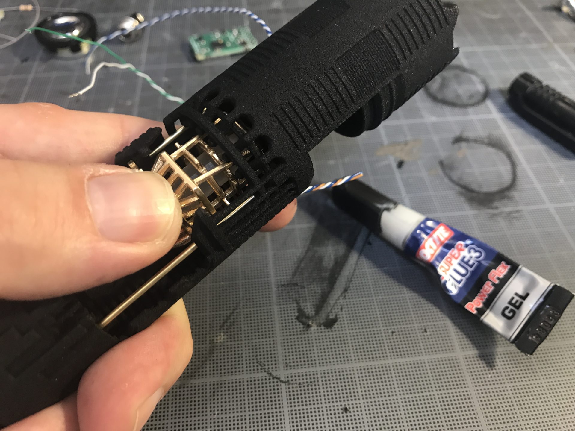
Notes: While it shouldn’t be required, test if your rods slide properly in the chassis first before the assembly. If it is getting hard to insert, cleaning the holes off printing dust might be required (which can be done using a drill bit with pliers, or using a 1.5mm OD rods with pliers, to force the residue out of the holes).
Step 4: Place CC insert 1 into the chassis, same as before, use a bit of super glue on the back fins to block the insert after inserting the 4 rods partially to guide it.
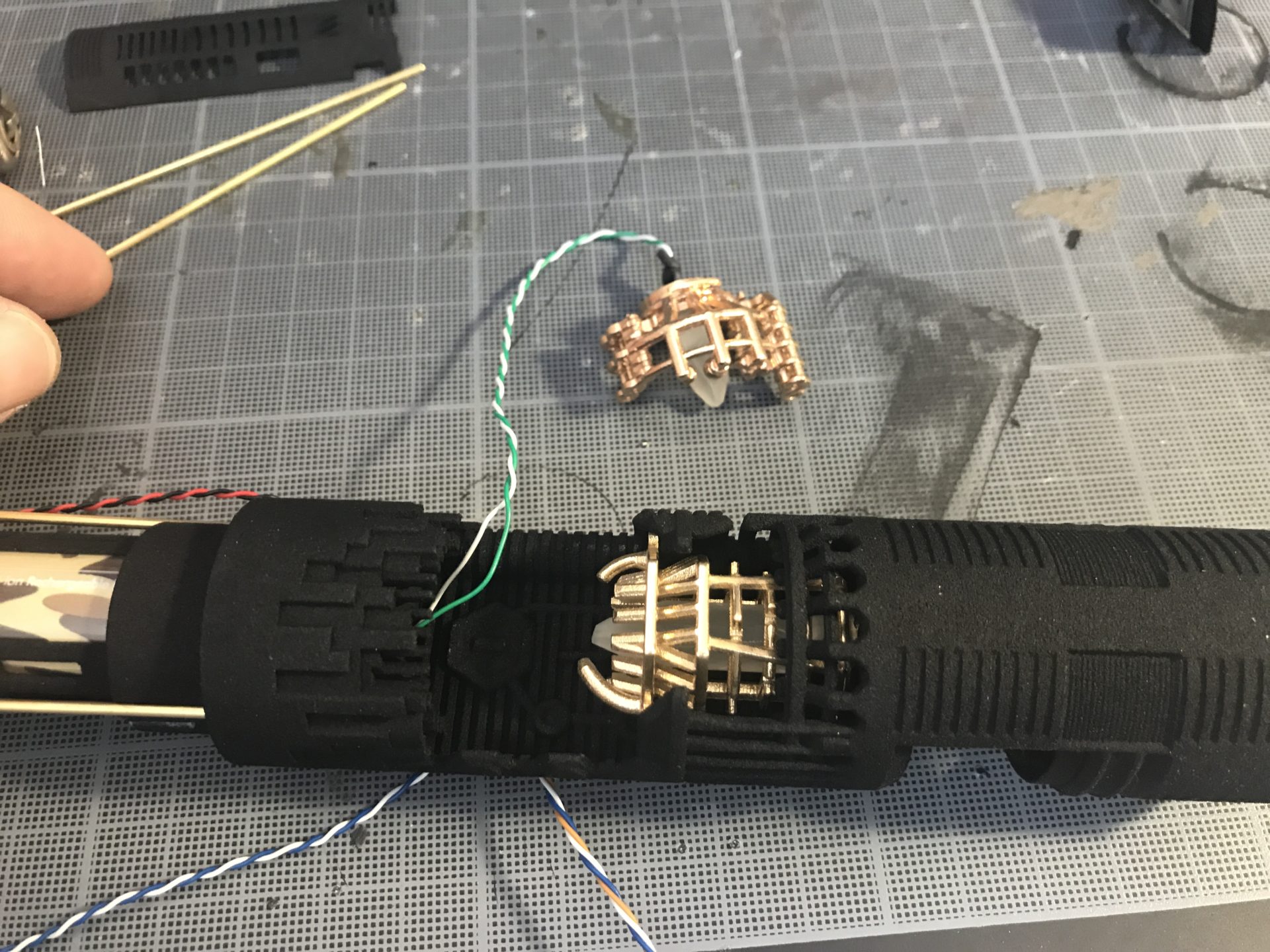

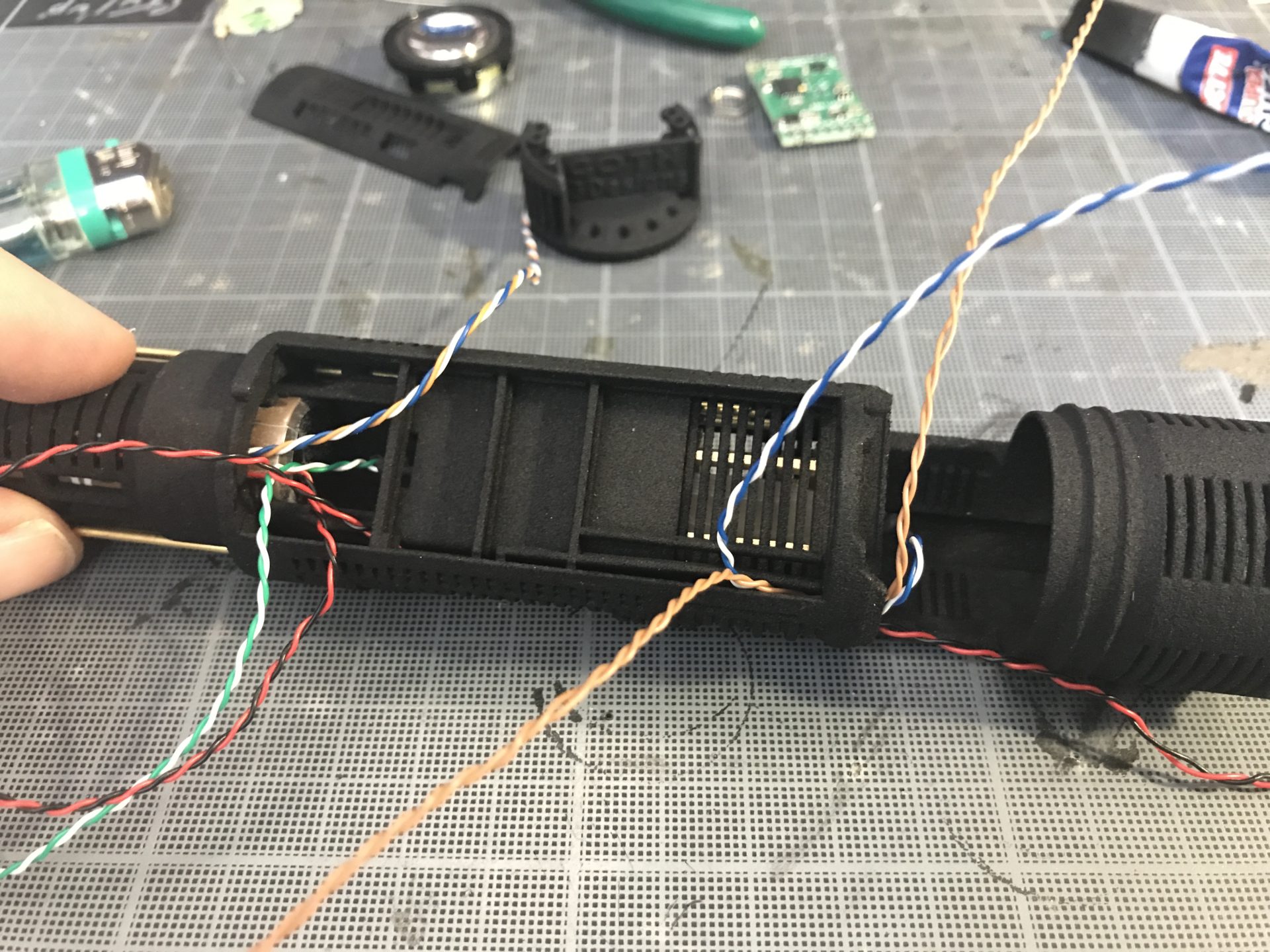
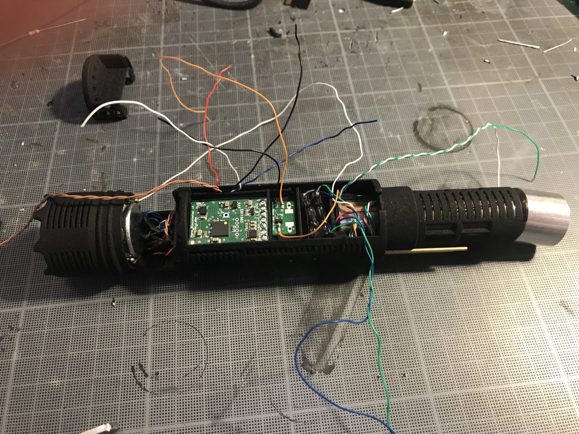
Step 5: Prepare the main led as we as the main switch wires (plan enough length). Then insert the battery into the chassis with the wires passing into the dedicated channel (the wires must be allowed to slide back and forth even with the battery in). You can secure the battery in place using tiny drops of super glue.
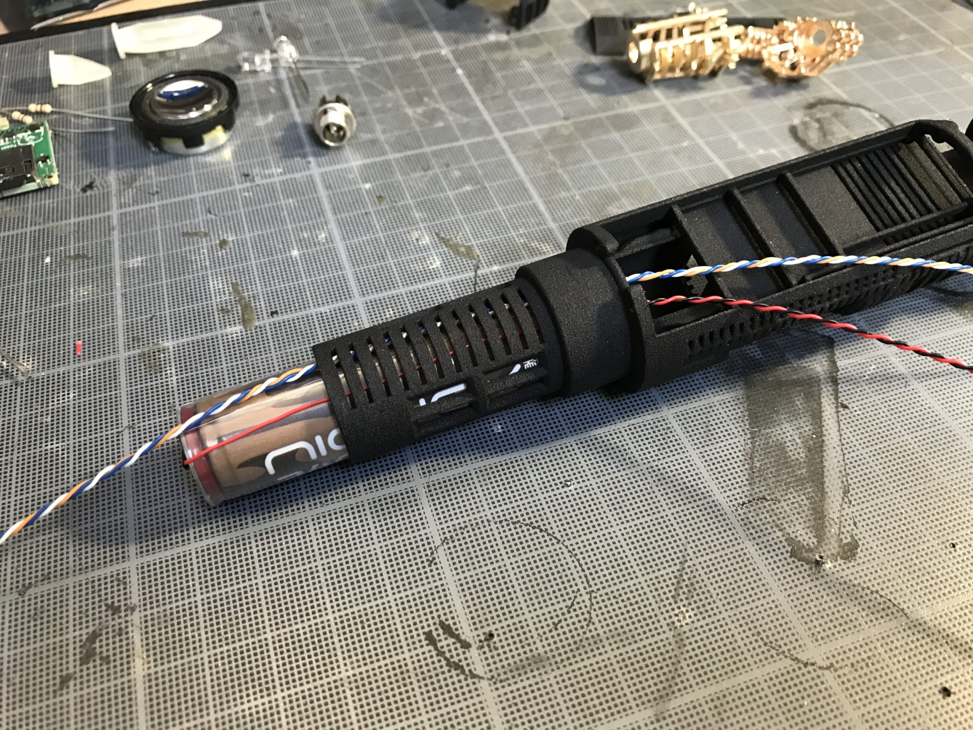
Step 6: There is a small round channel on the right of the chassis to pass the battery wires (and the speaker wires, accents led 2 wires, …). The battery wires going to the recharge port must then pass in a dedicated channel as shown below in order to avoid wires touching the speaker.
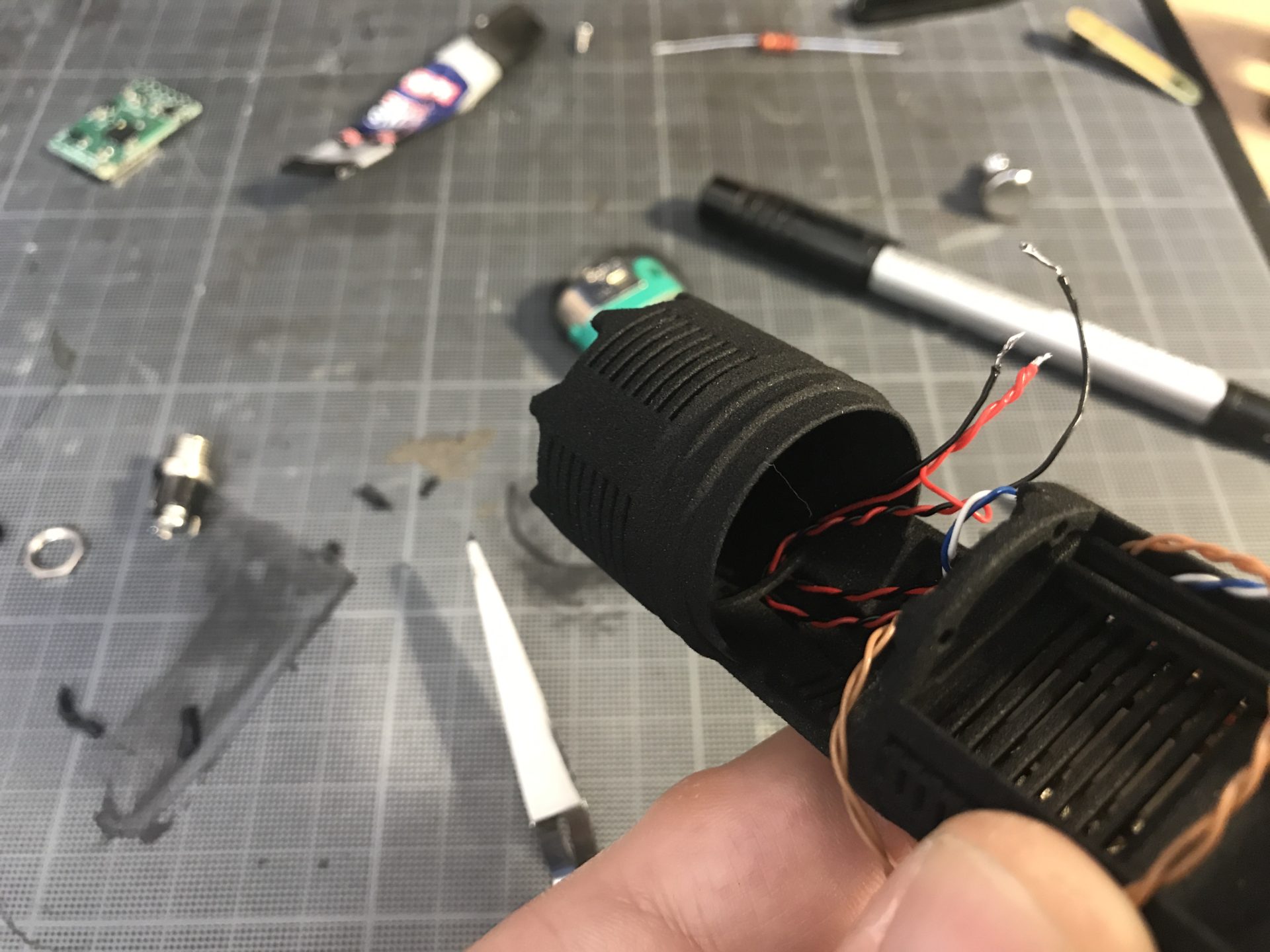
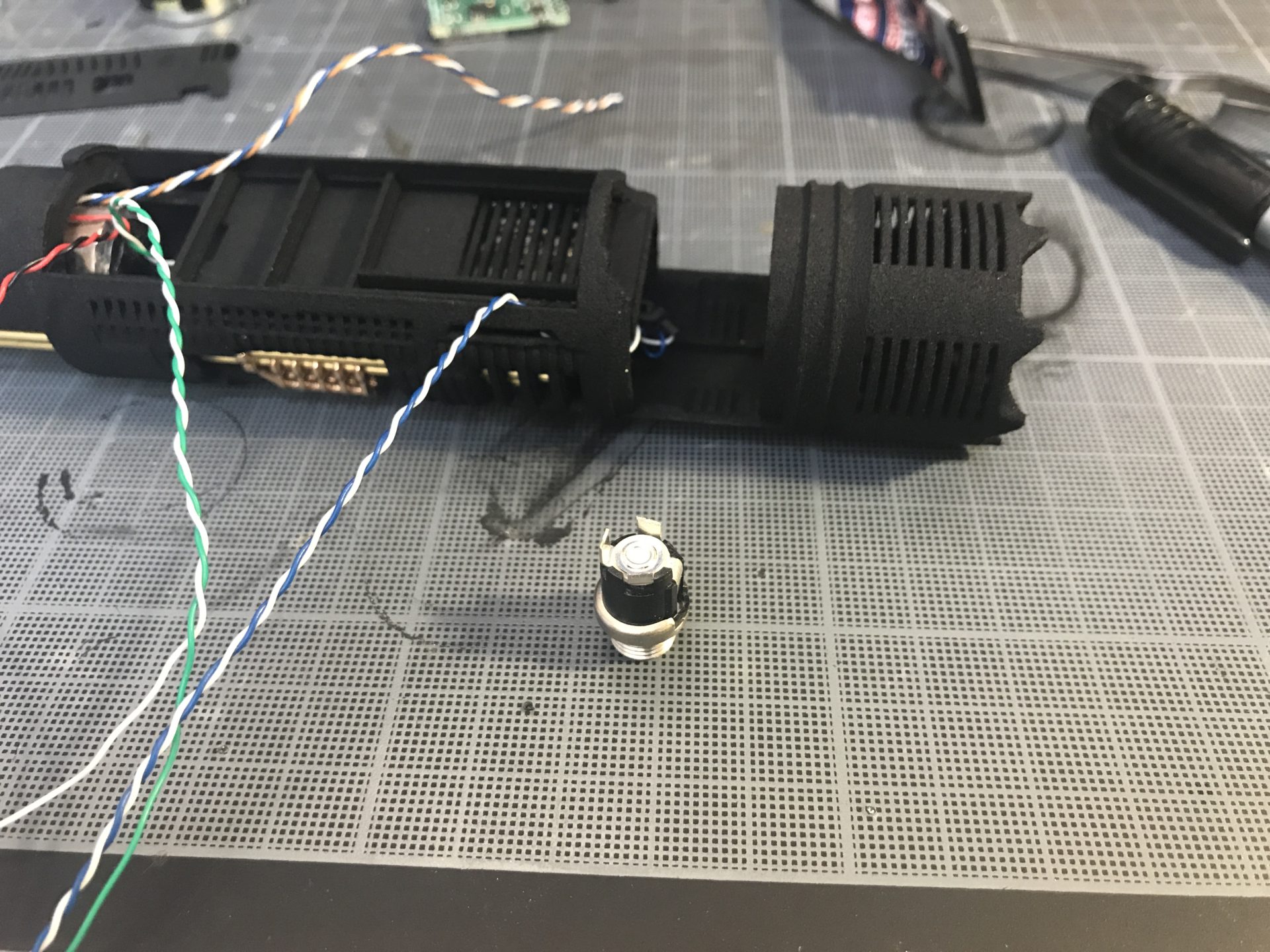
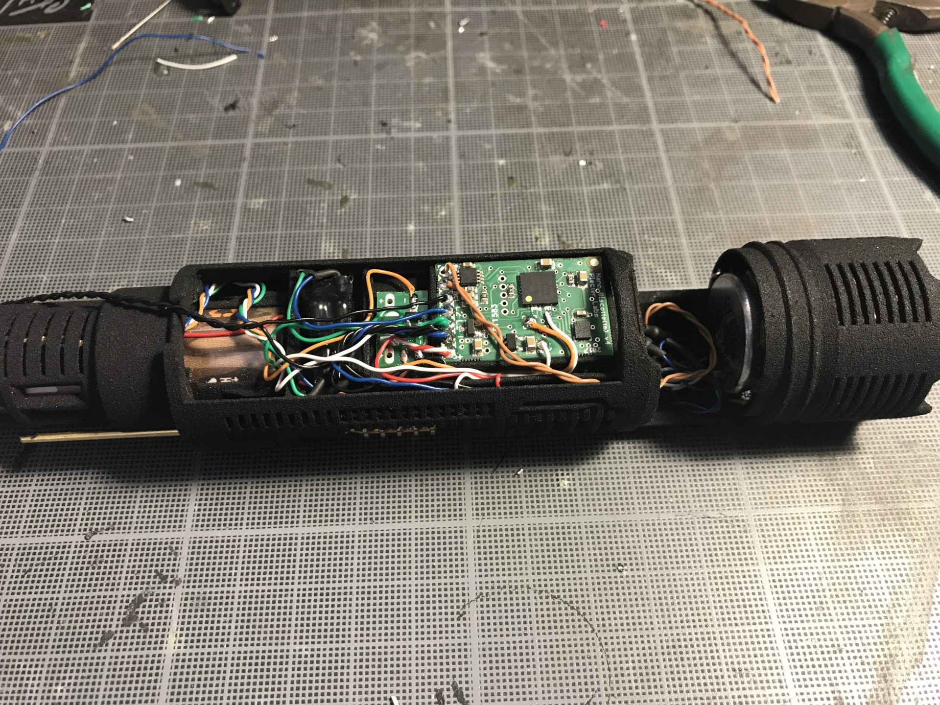
Step 7: Wire the recharge port. The leads have to be cut to the minimum length, and the wires have to exit flat / on the side, again to avoid touching the speaker). Then insert your recharge port and secure it with its associated hex nut.
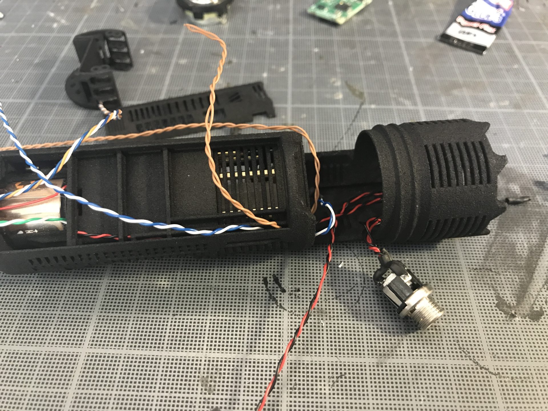
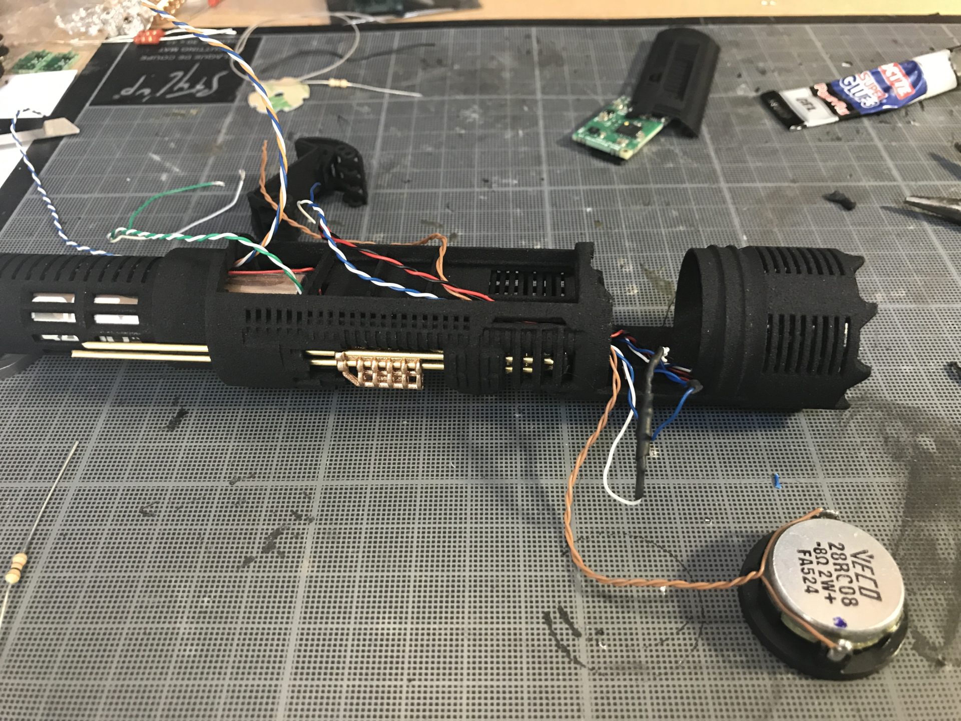
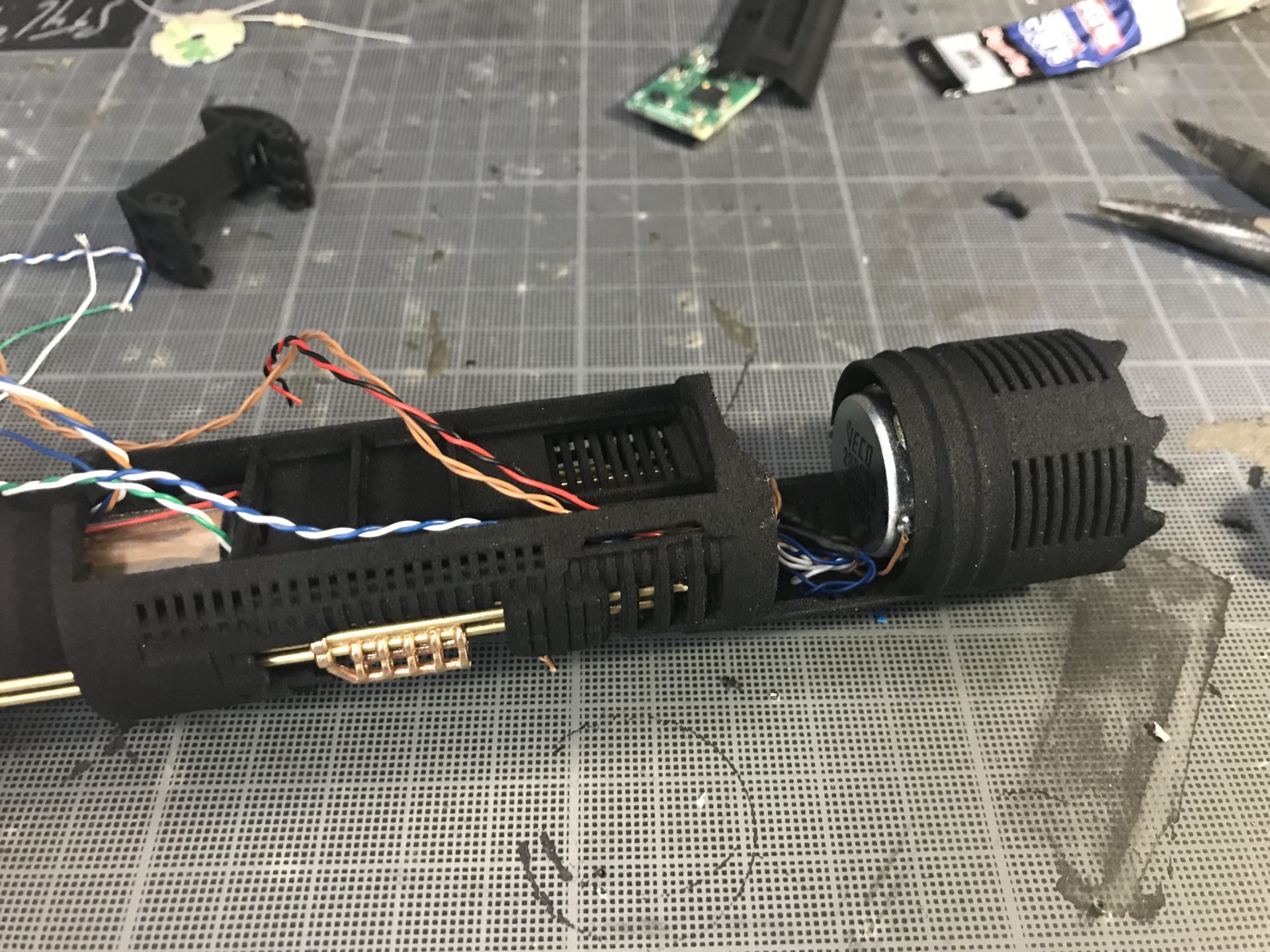
Step 8: Wire the speaker and insert it in the holder. You can secure it with a tiny bit of sure glue (but better test everything before).
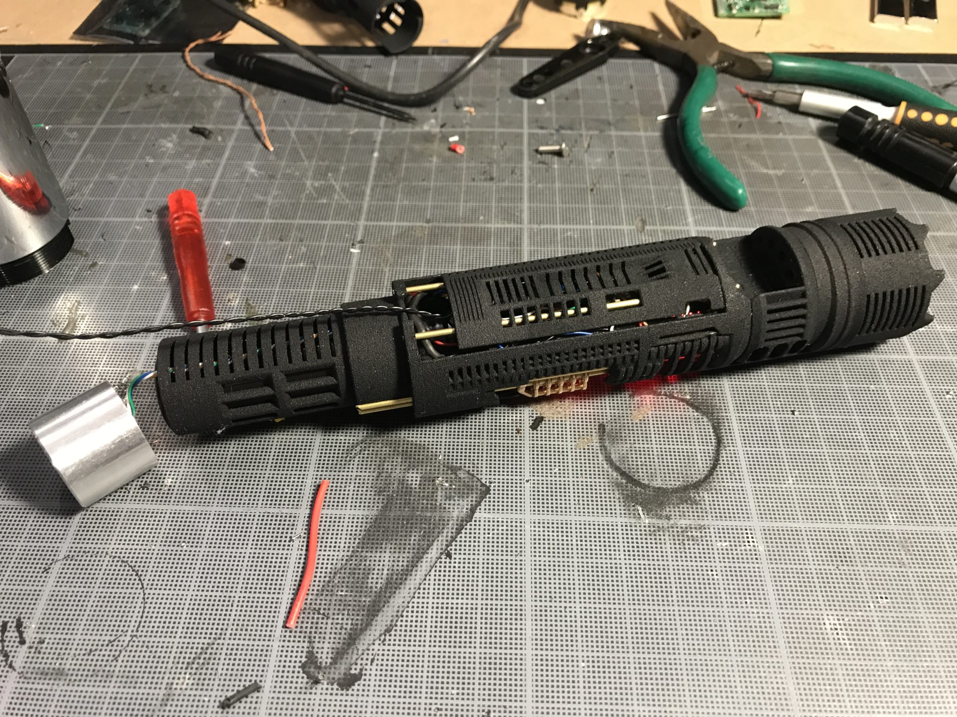
Step 9: Wire your main LED, and install into it’s dedicated 7/8 heatsink.
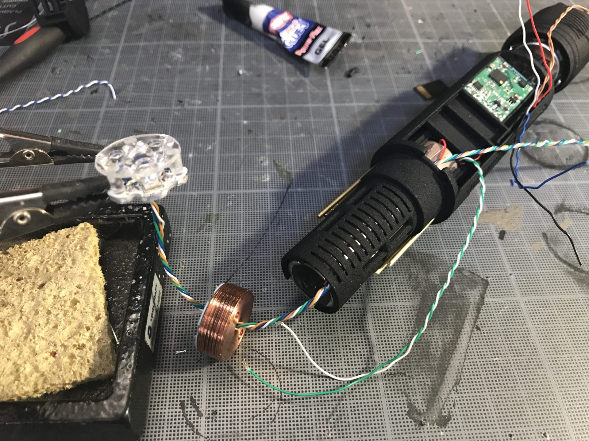
Step 10: Wire your soundboard.
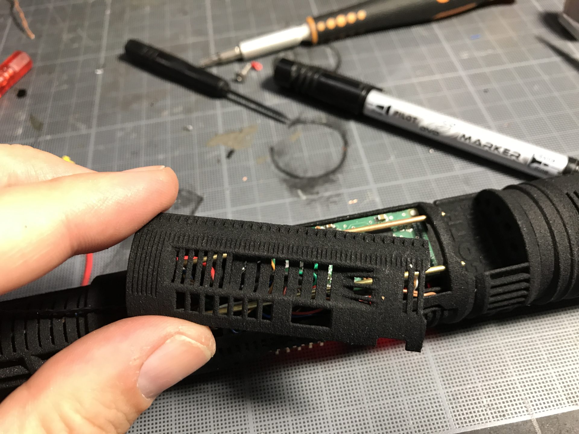
Step 11: Make sure to test everything. Then you can place the part to cover the speaker and recharge port wires. Time to push the rods entirely in.
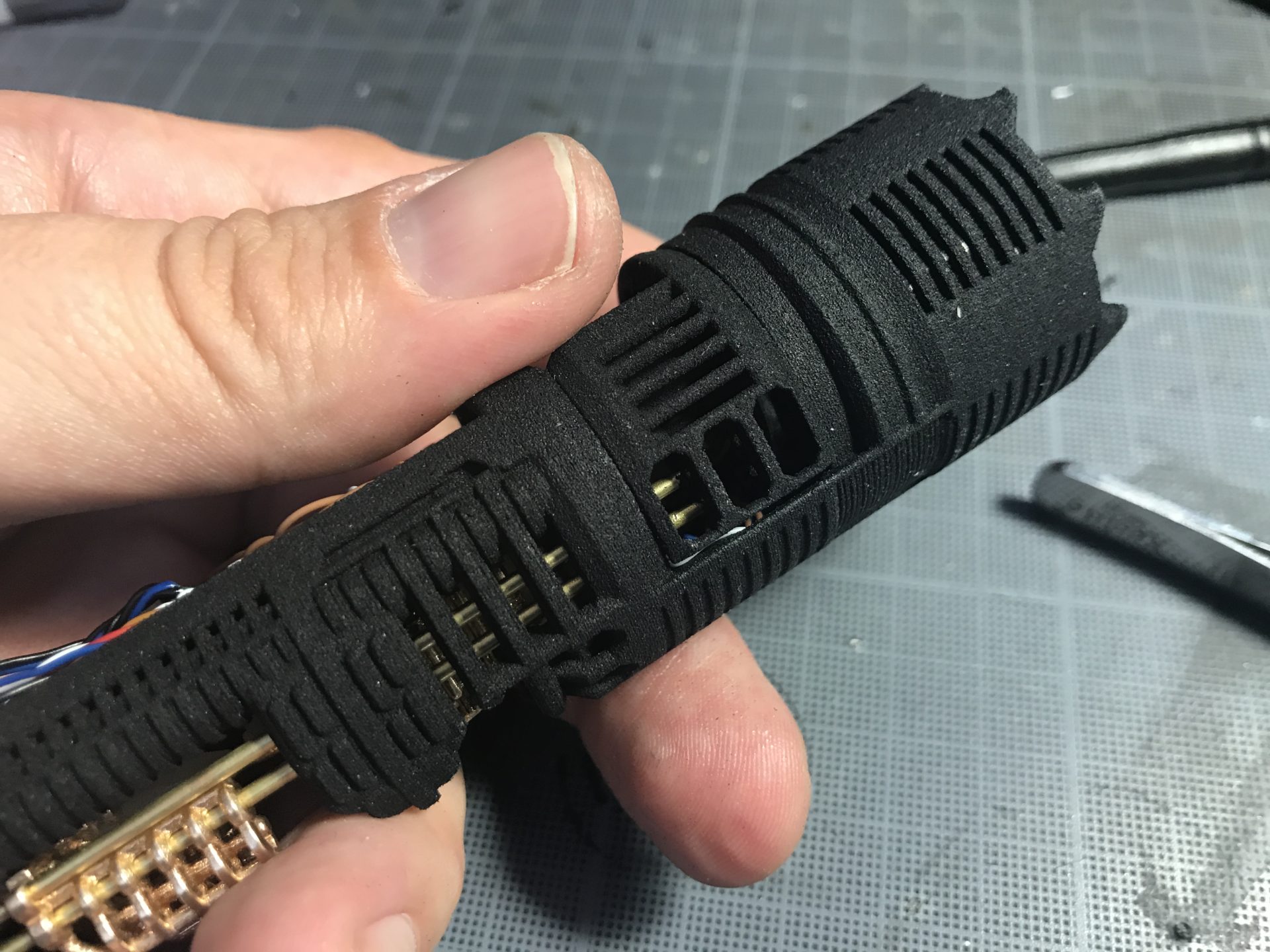
Step 12: Cut the soundboard cover rods to the right length (insert one and mark where to cut), then clip the cover on the rods.
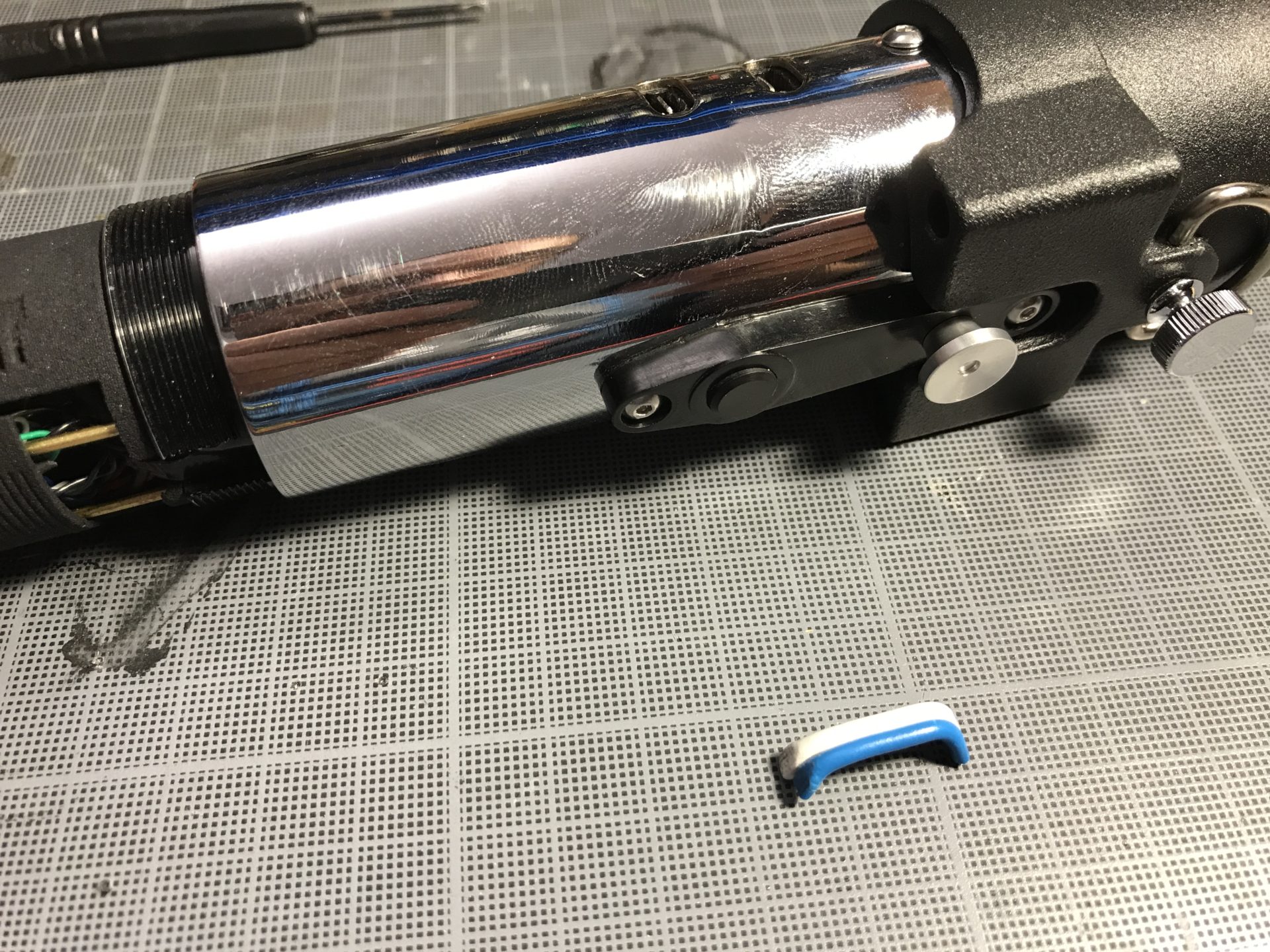
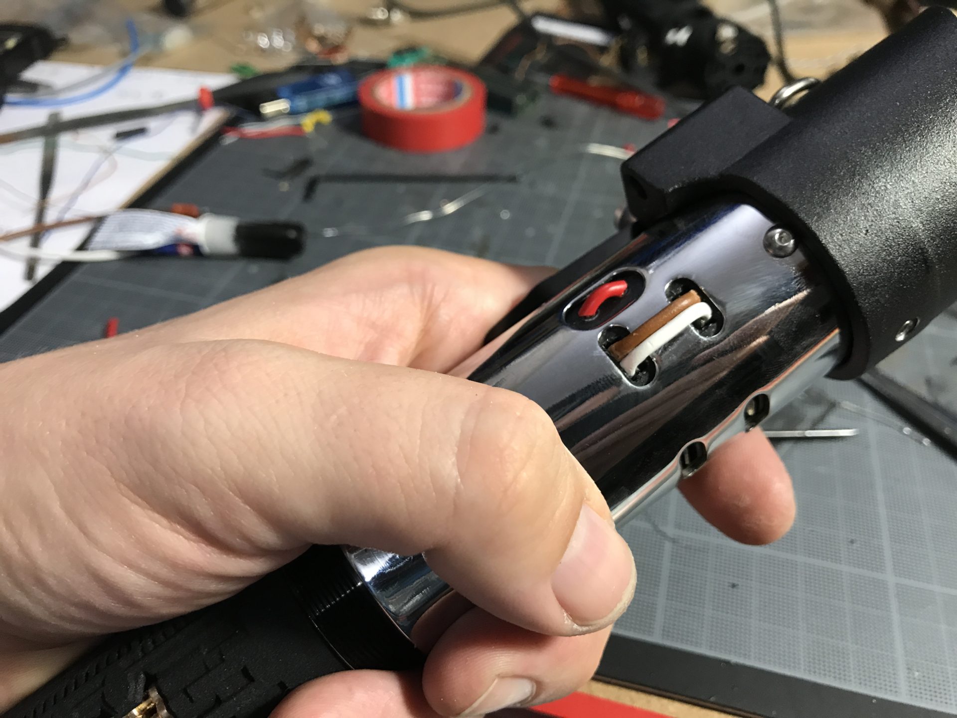
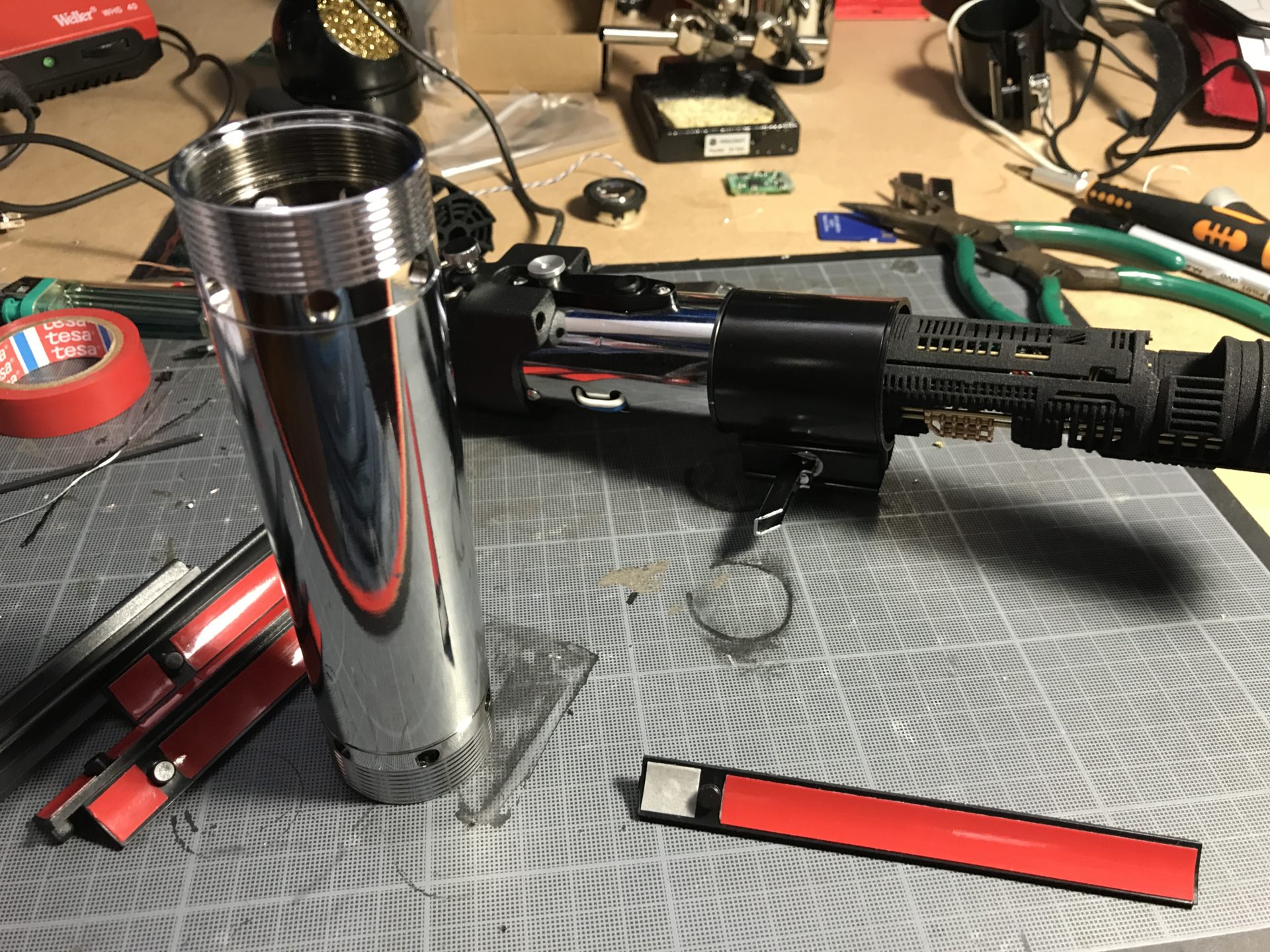
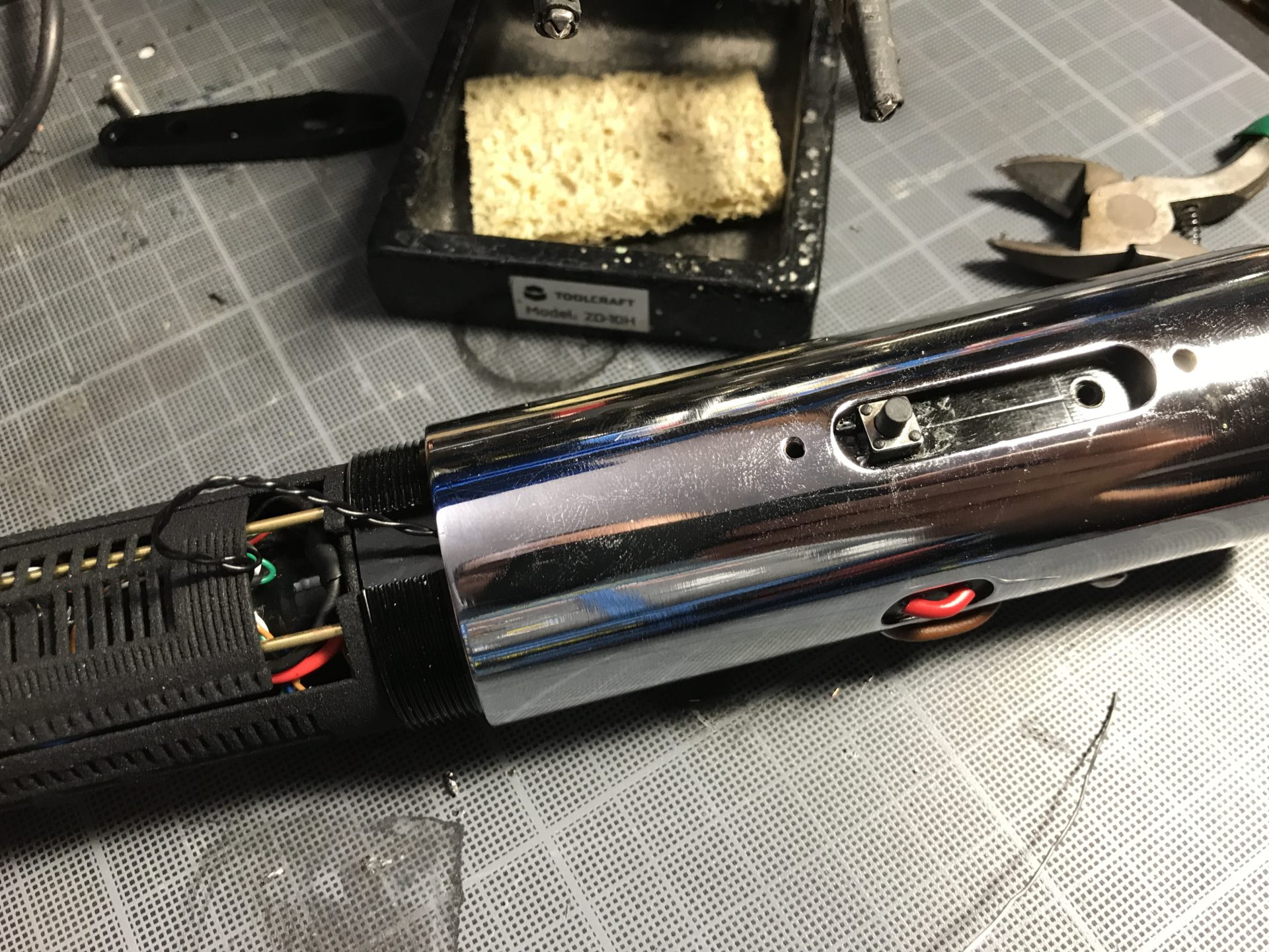
Step 13: place the chassis in the main hilt section. The main switch wires (and eventually Aux switch in the clamp) do not go inside the 7/8″ID tube.
Step 14: Regarding the main switch provided with the hilt, we recommend sanding everything on the bottom and protect it with electrical tape. Then solder the wires as shown below. To do so, pass the main switch wires in the dedicated channel over the main body and under the chromed shroud, the solder them on the switch top side. Inset your switch into the slot (sanding might be required for the PCB to fit properly), and pull the wires back to be hosted over the battery.

Step 15: Finish assembling your hilt (eventual ESB wires and grips).