NWL Rebel Orphan (2018) Master Chassis

These designs are no longer supported (FAQ)
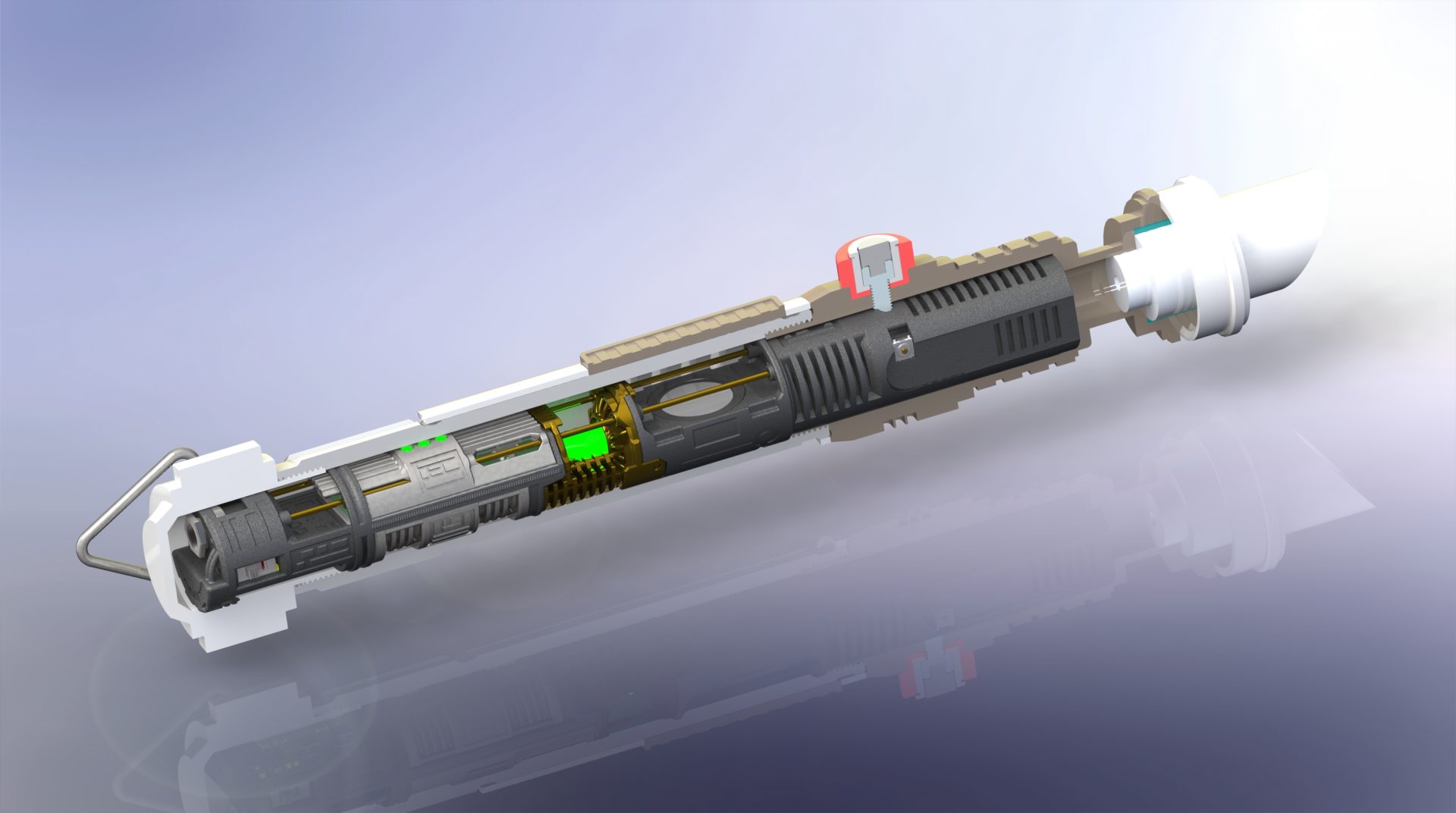
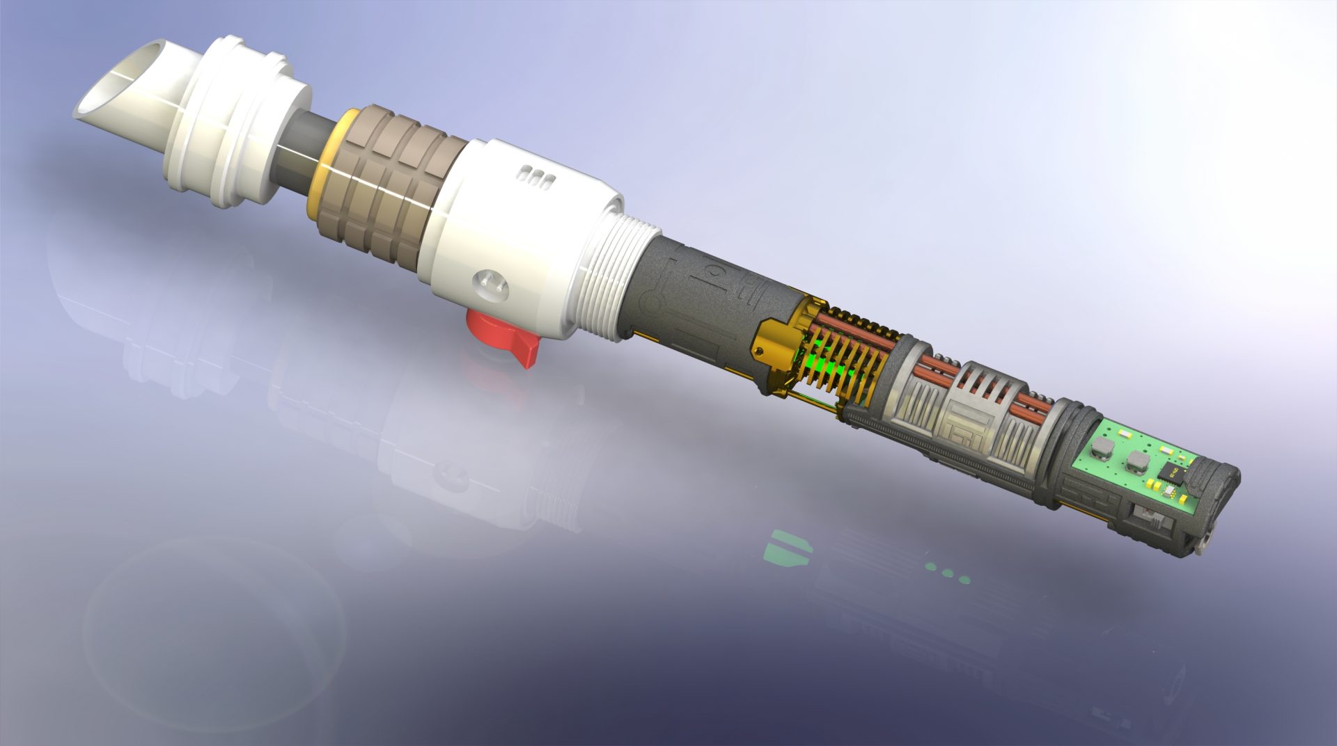
Master Chassis:
Multi-parts chassis assembly with metal elements.

⇒ Part 1 – Main Chassis: nwl-ezra-master-part1-lightsaber-chassis
⇒ Part 2 – Crystal Chamber: nwl-ezra-master-part2-lightsaber-chassis
⇒ Part 3 – Shell1: nwl-ezra-master-part3-lightsaber-chassis
⇒ Part 4 – Shell2; nwl-ezra-master-part4-lightsaber-chassis
⇒ Part 5 – Optional Crystal: nwl-ezra-master-part5-lightsaber-chassis
Padawan Chassis:
All-in-1 chassis for simple install.


⇒ All.In.One nwl-ezra-padawan-lightsaber-chassis
Additional chassis parts:
Here is a list of parts needed to install the Master chassis:
⇒ 1.5mmOD rods x3
⇒ 3mmOD tubes x2
DEMO
Quick Install Guide:
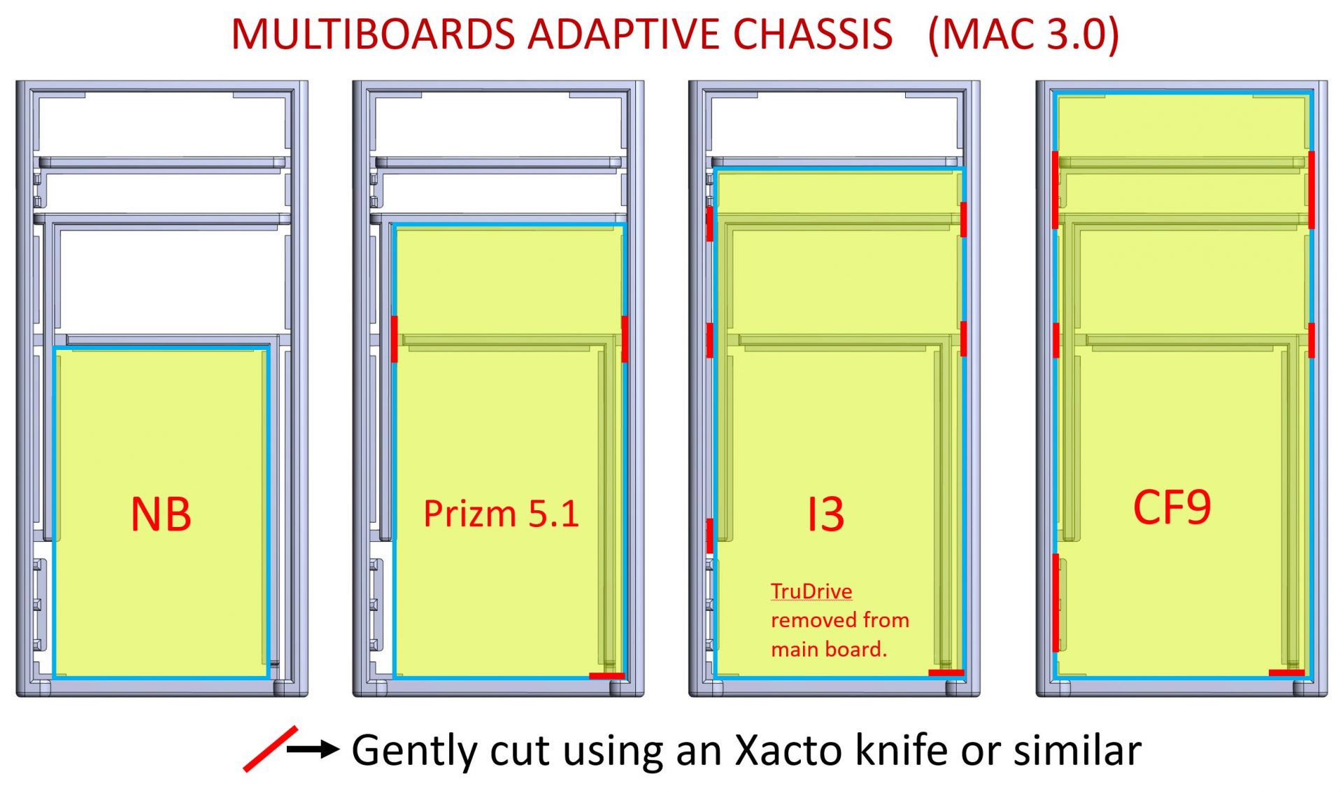
MULTIBOARDS ADAPTIVE CHASSIS
Install the soundboard with the SD card on top, facing the pommel.
Follow this pattern to install the soundboard of your choice:
Disclainer:
– These instructions will details the install procedure as much as possible. GOTH-3Designs cannot be held responsible for any mistakes made by DIYers.
– Always wear protective gear when working on install (gloves, eye protection, …), GOTH-3Designs cannot be held responsible in case of accident.
Note 1: The picture below are taken from a prototype chassis. Some small design changes occurred in the final version.
Note 2: We do not cover wiring instructions, please read your soundboard manual before starting the install.
Note 3: 30awg wires and smaller are mandatory for this install (30awg for main wires and 32awg for accent leds and switches are mandatory).
Note 4: Thanks to read the full instructions before starting your install. Commission an installer to build the hilt for you, if you feel unsure about what to do.
Note 5: Always test your install along the way and make sure everything works. It takes time, but better safe than sorry later when it is more difficult to come back.
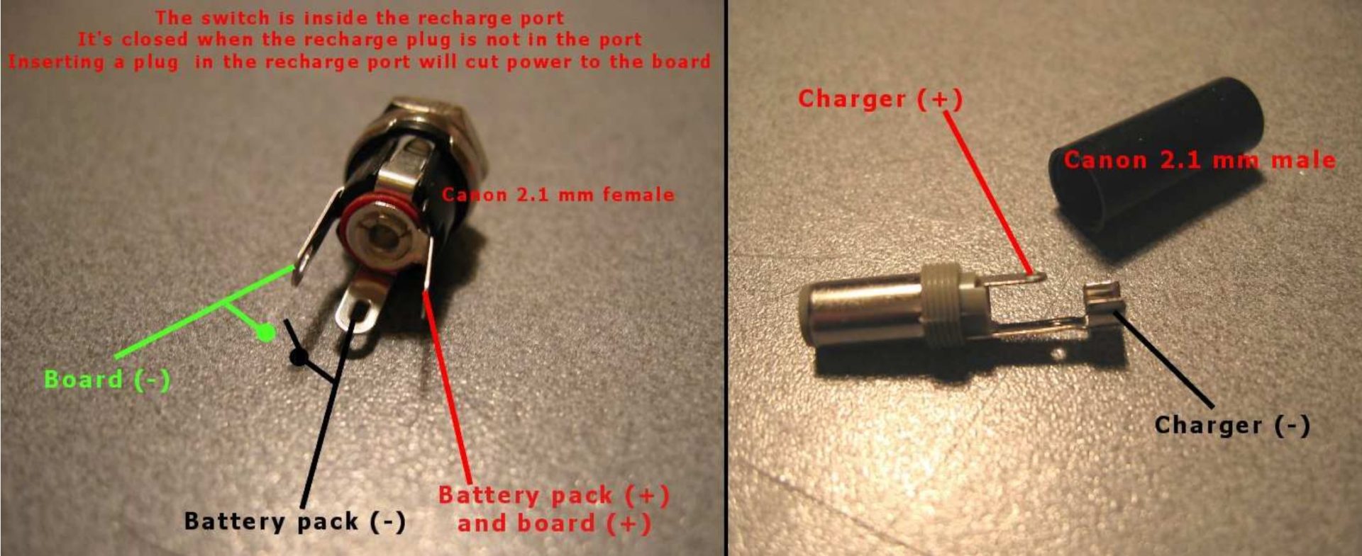
Note 6: Recharge port wiring reminder:
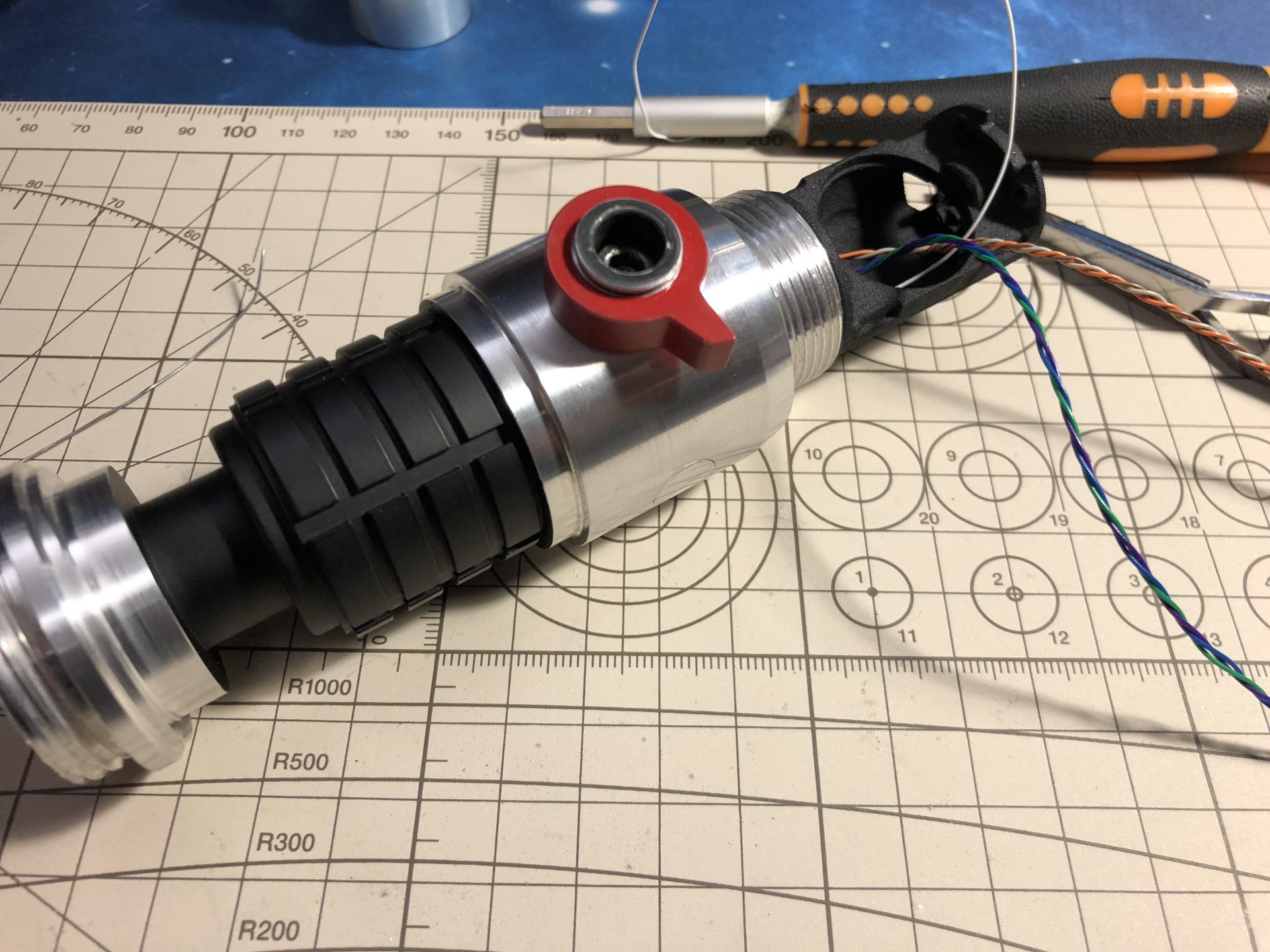
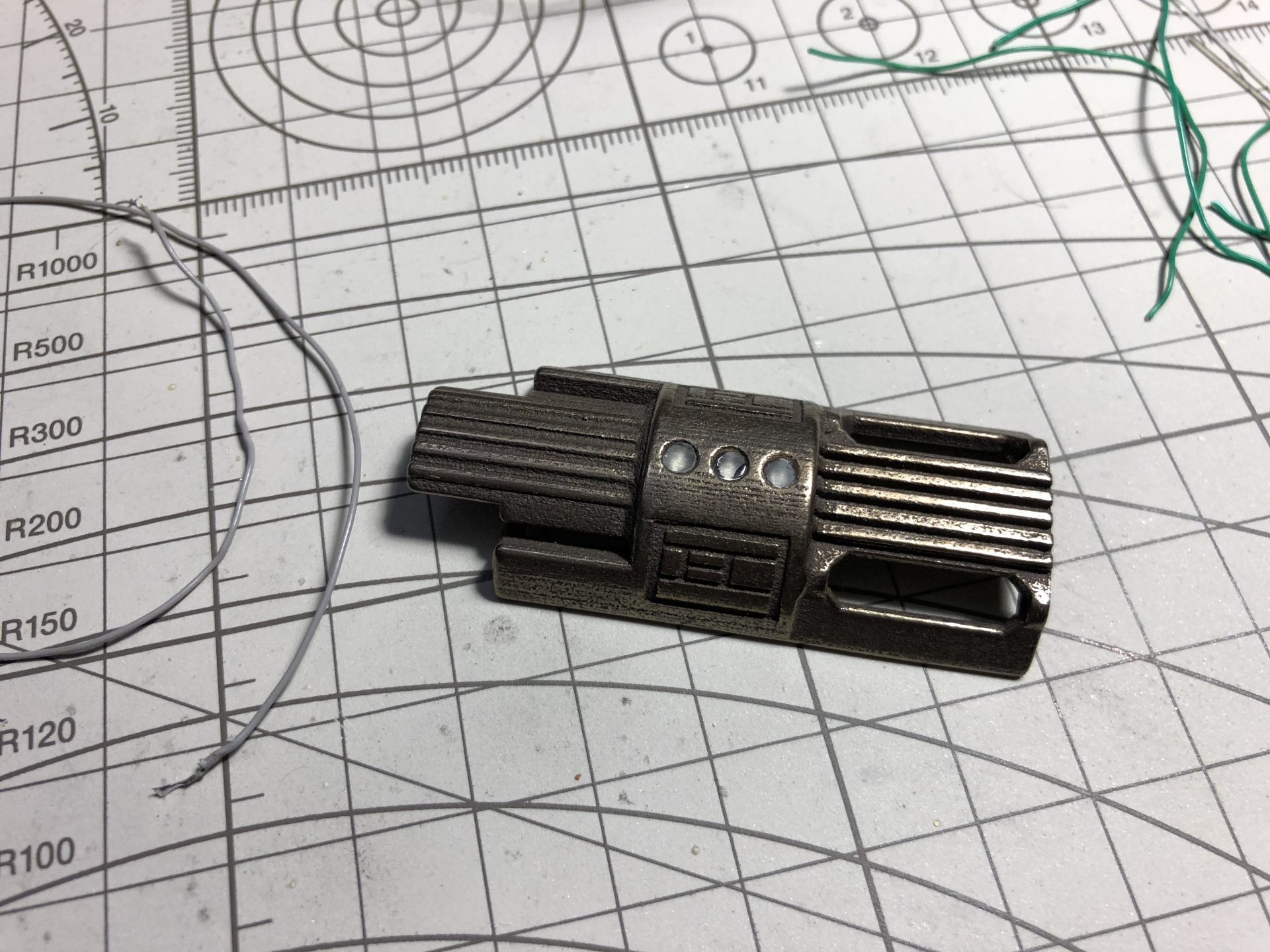
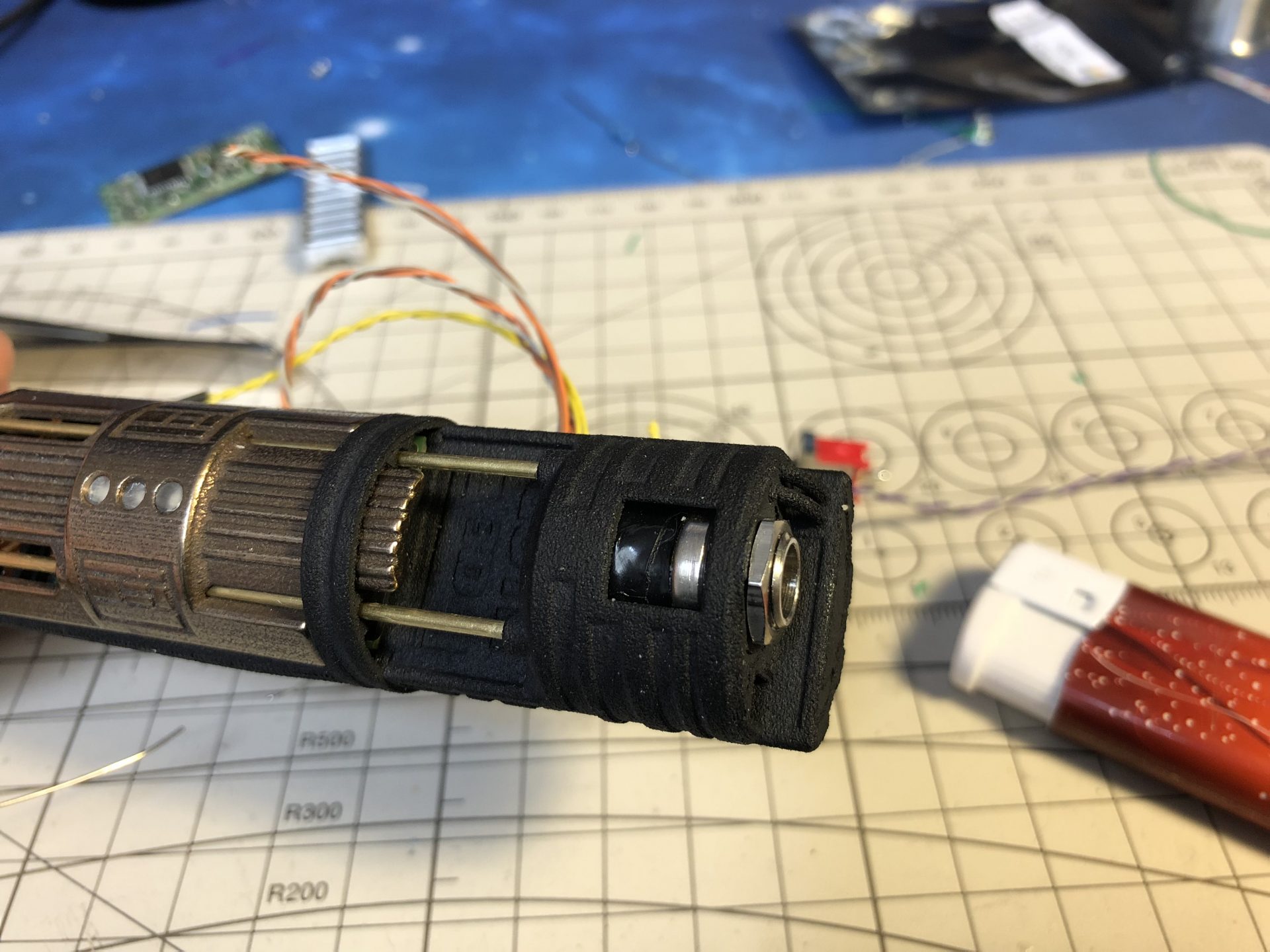
Step 1: Switches and battery install
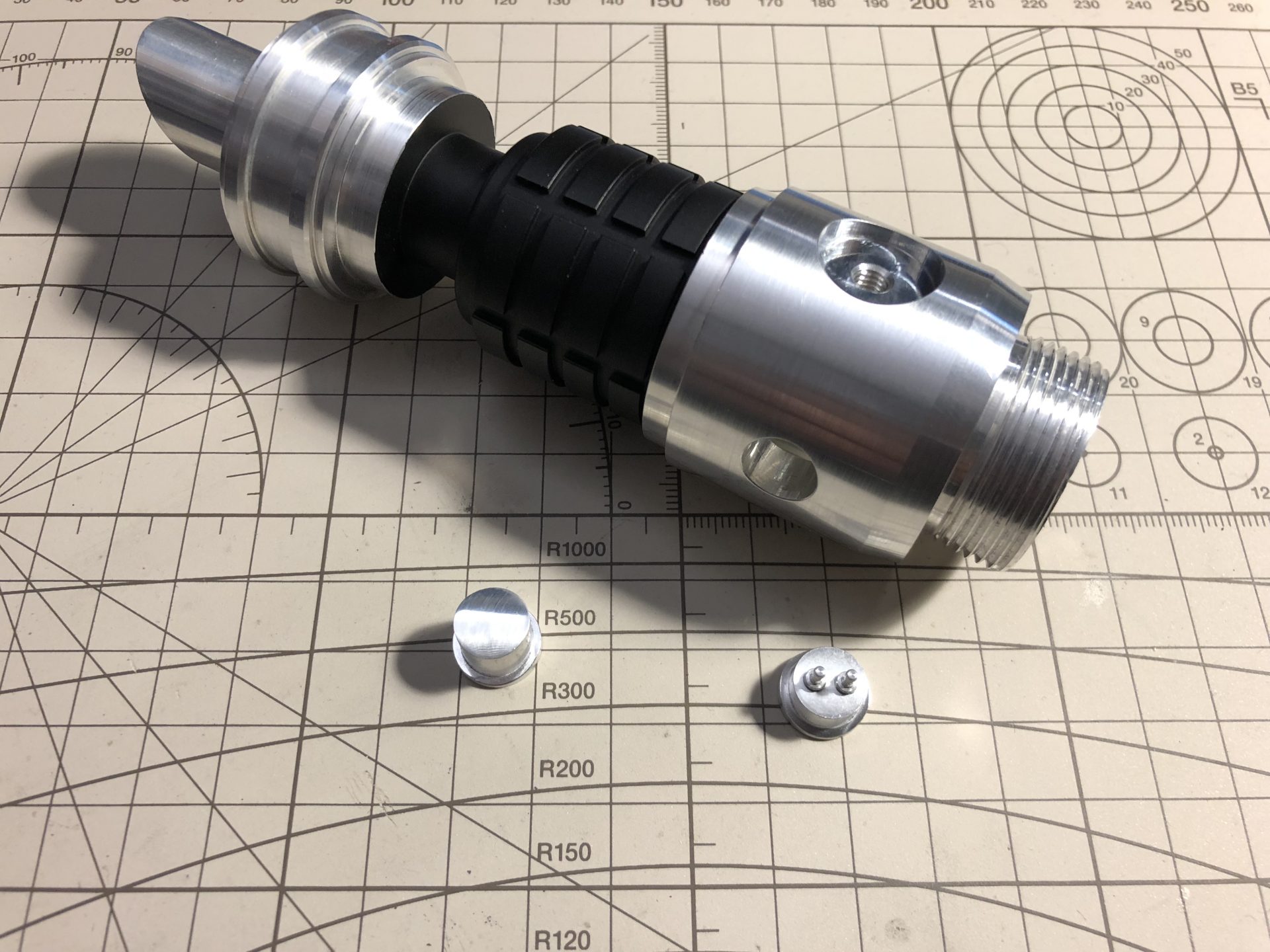
The hilt comes with 2 plungers, one plain and one with pins.
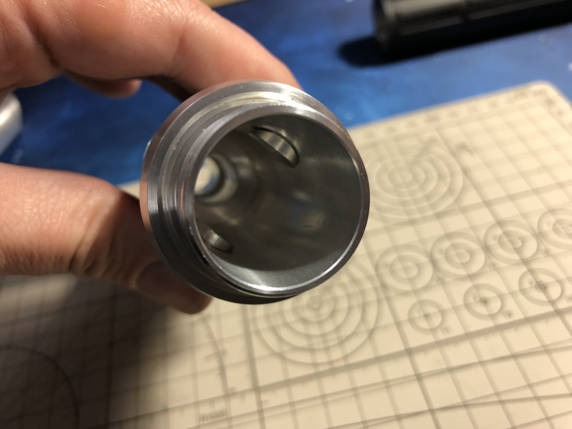
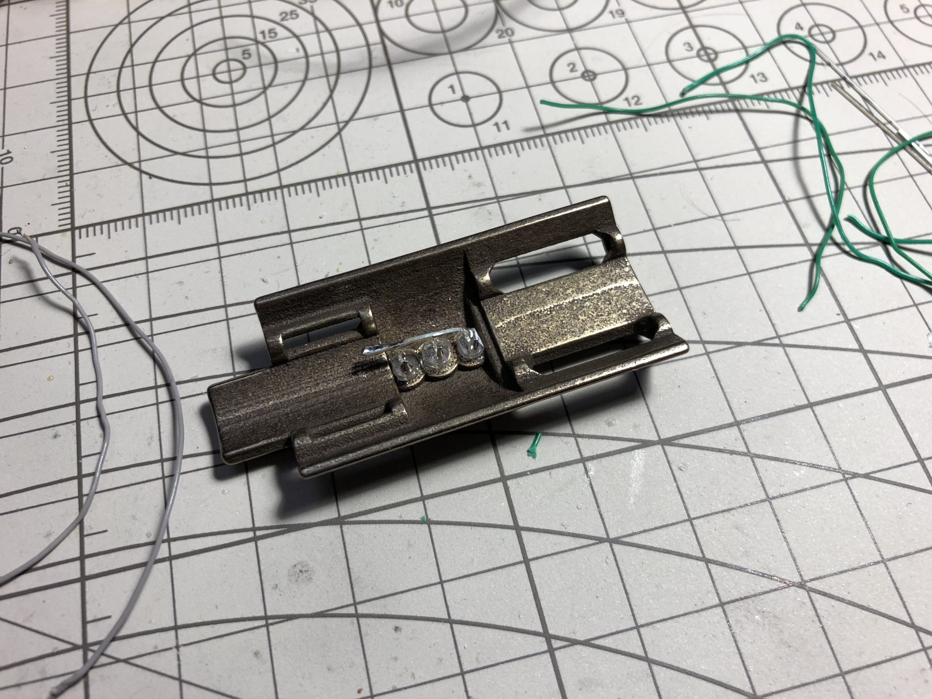
Glue the pins, and optionally polish the plain plunger, then add the plain on the left and the pins plunger on the right of the hilt emitter part as shown below (make sure they slide in easily).
Add enough length of wires for the main led and switches wires, to be passed through the dedicated channel over the battery holder.
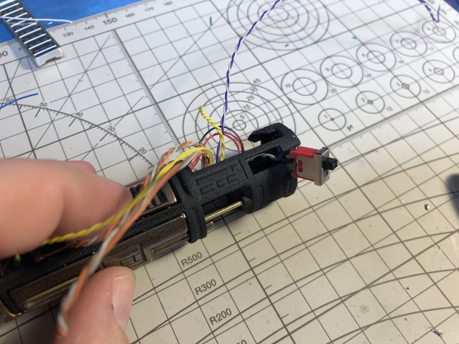
Then make the switch wires exist on each side of the chassis as shown below.
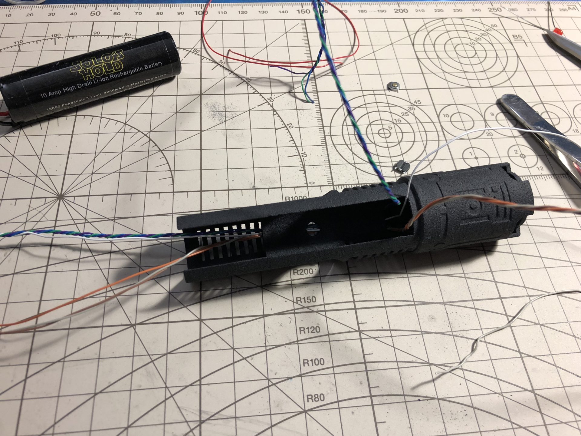
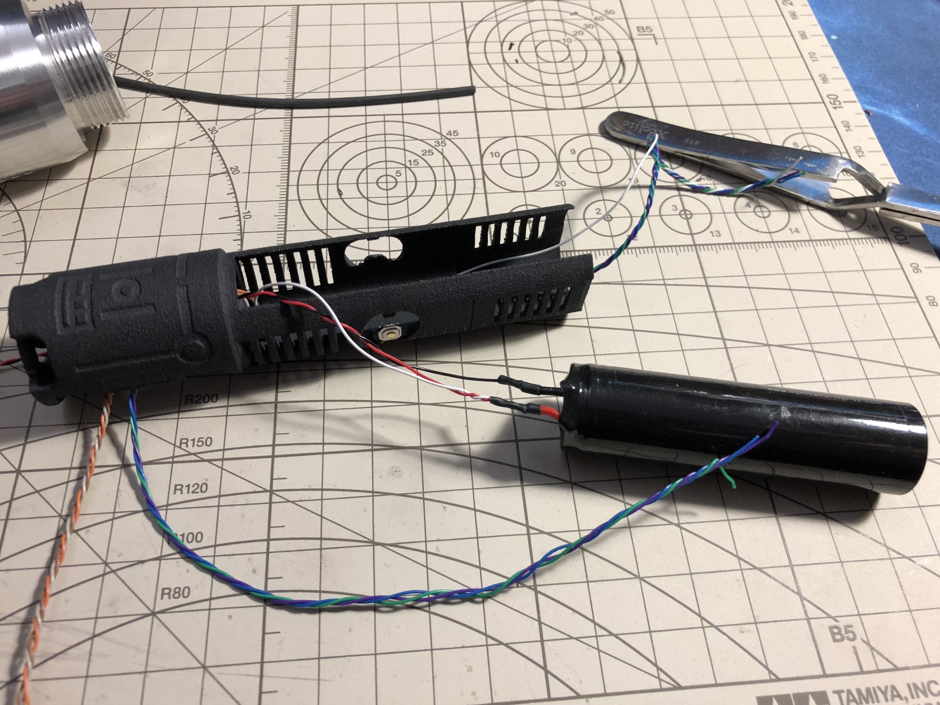
Solder the 1.5mm brass switches
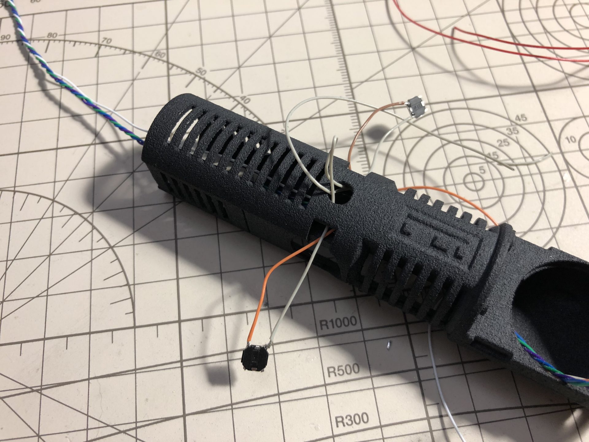
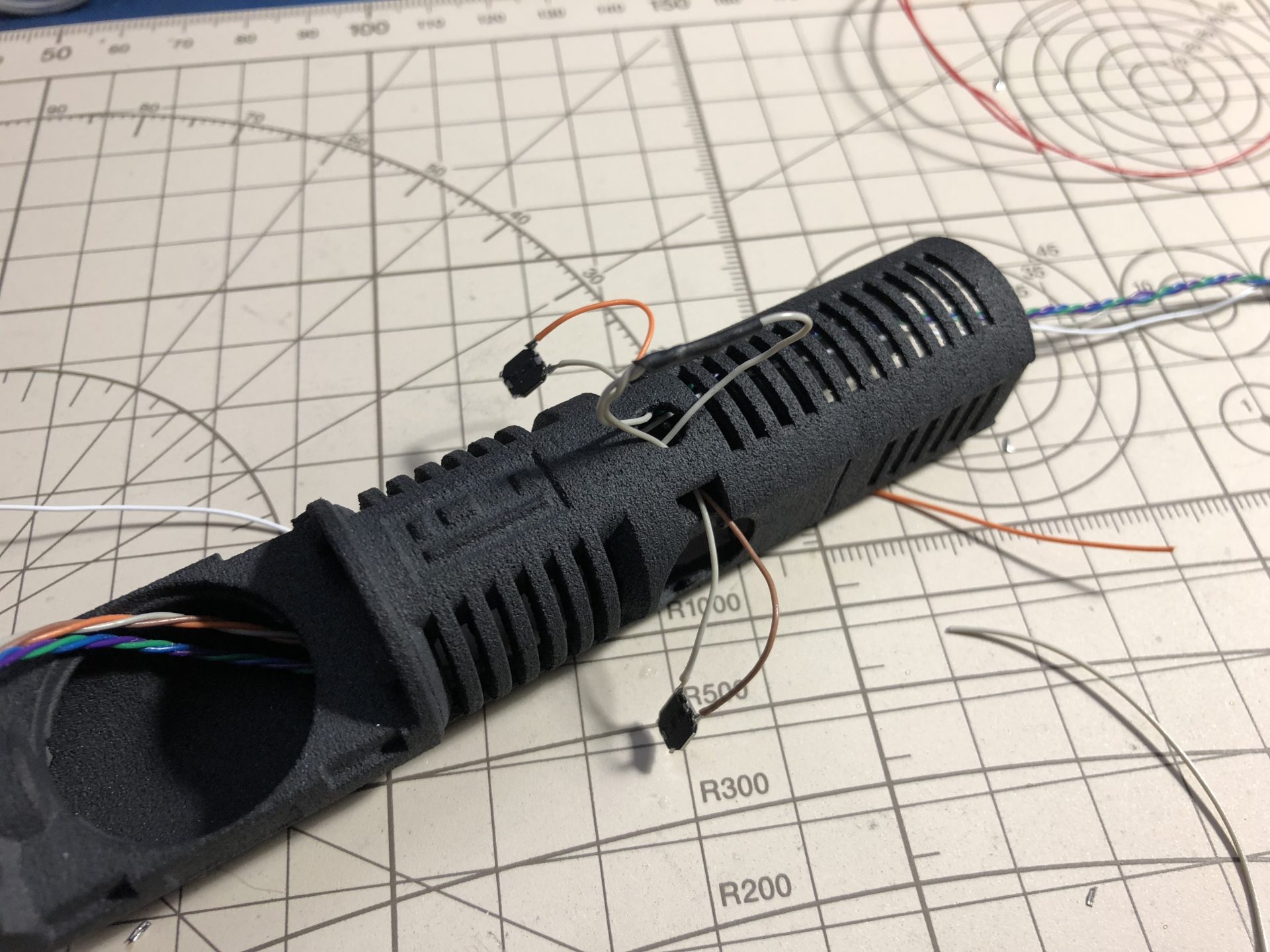
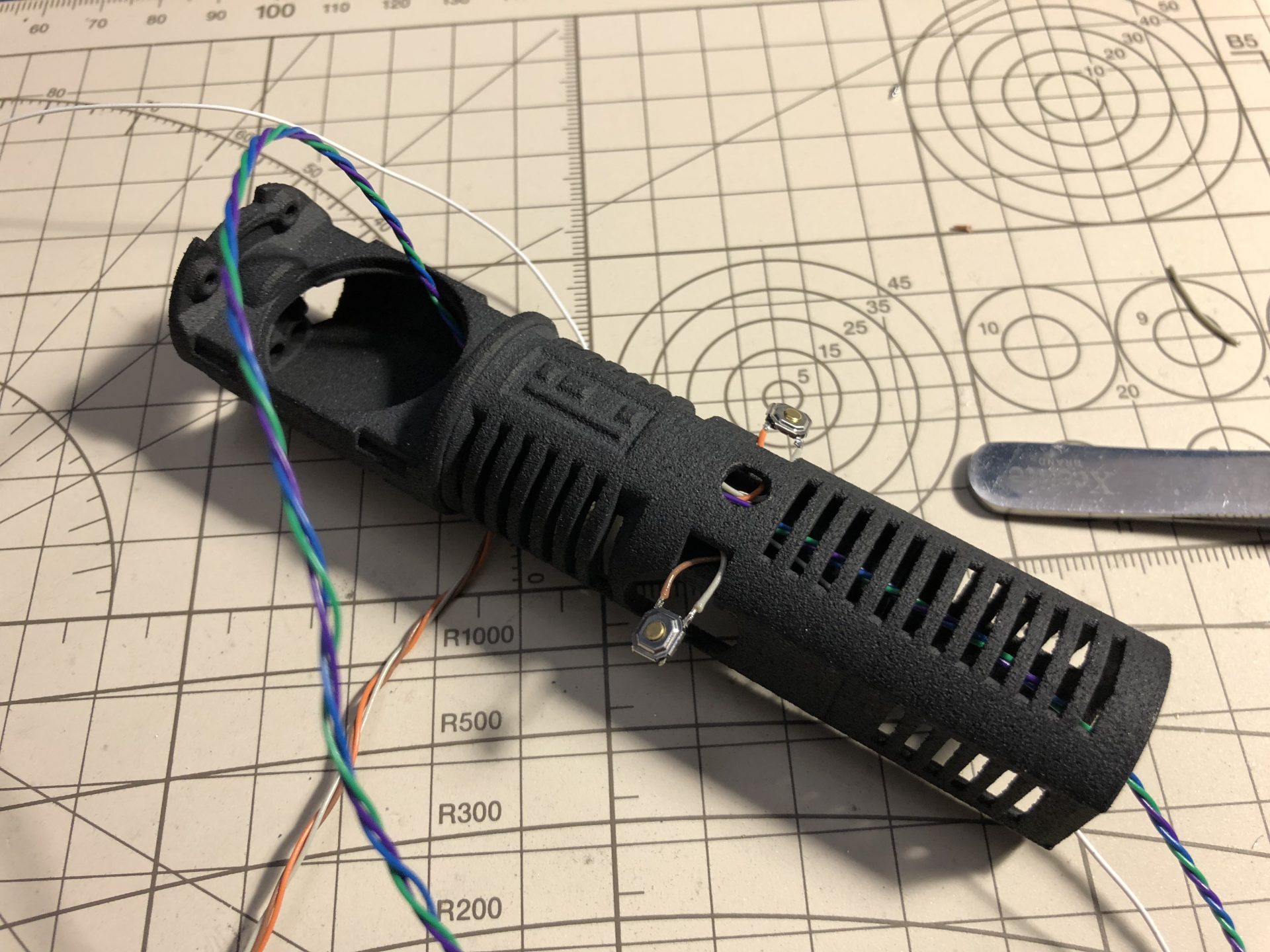
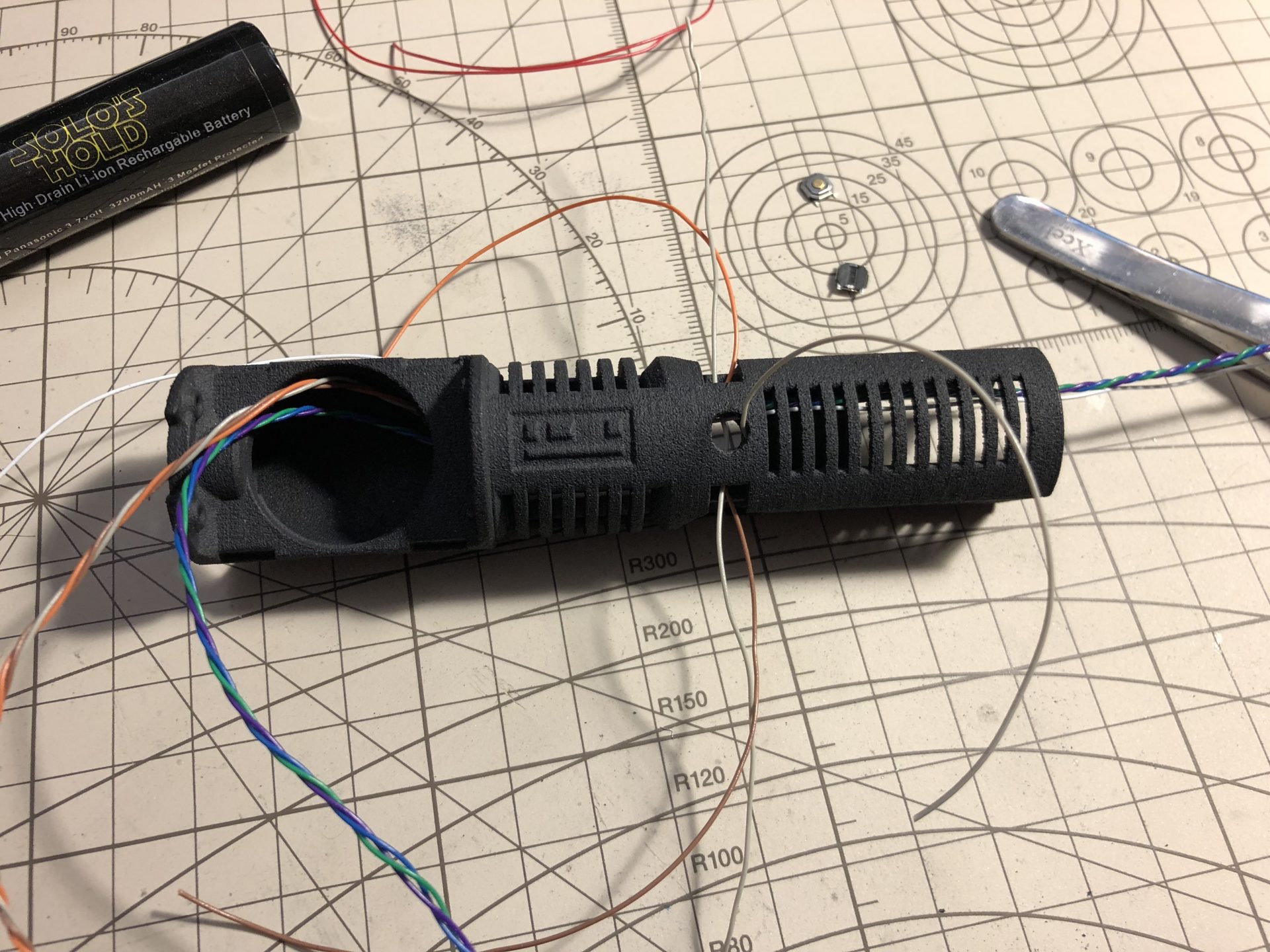
The switches have to be glued on the chassis, they rest half on the chassis, half on the battery (glue only on the chassis).
Insert the battery to place the switch properly, glue them and pull the wires in.
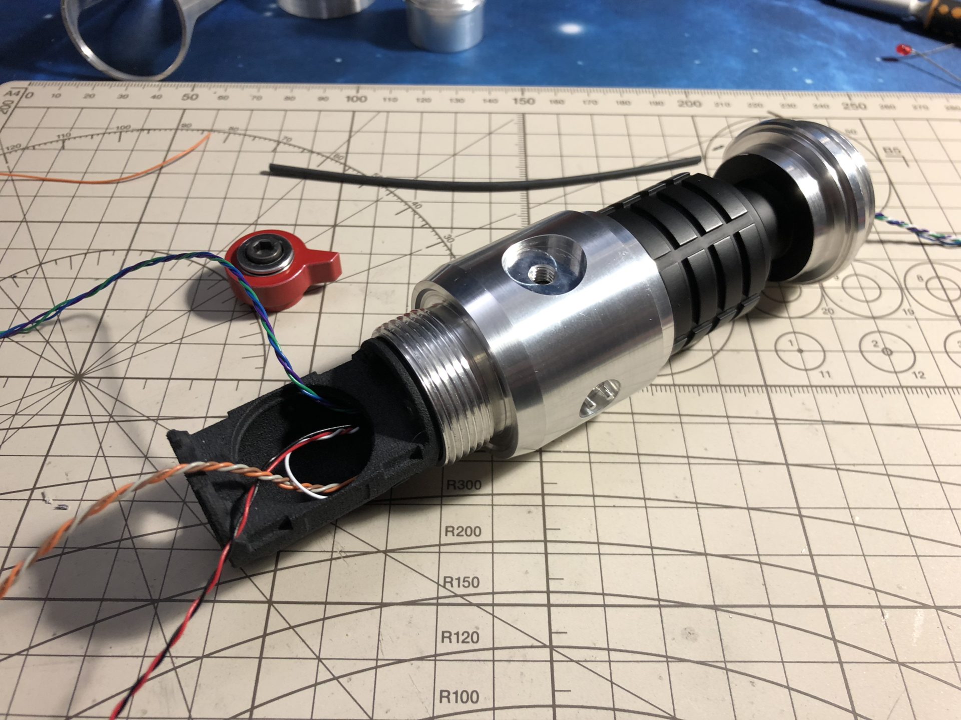
It is then mandatory to insert the chassis into the upper hilt part to test the switches work fine. The red lever screw is used to lock the chassis in.
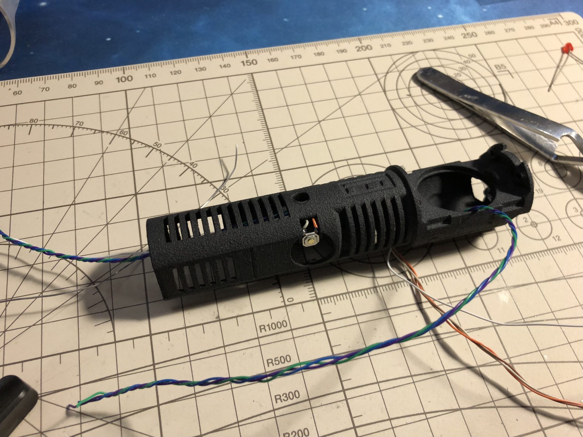
Once the switches install test, finish the upper chassis by adding the battery (tiny bits of super glue are used to secured the battery in place).
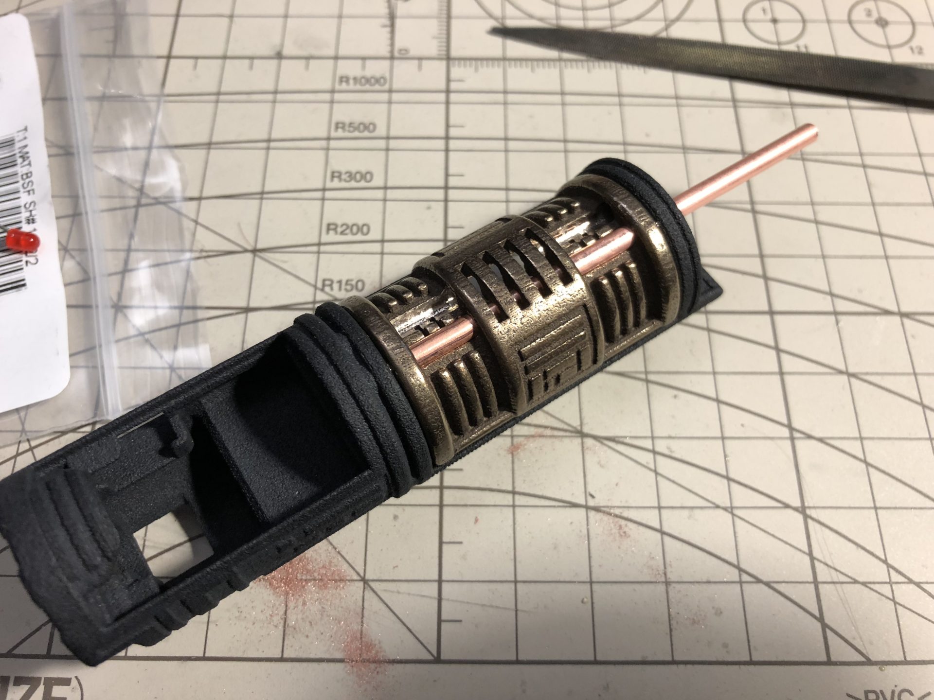
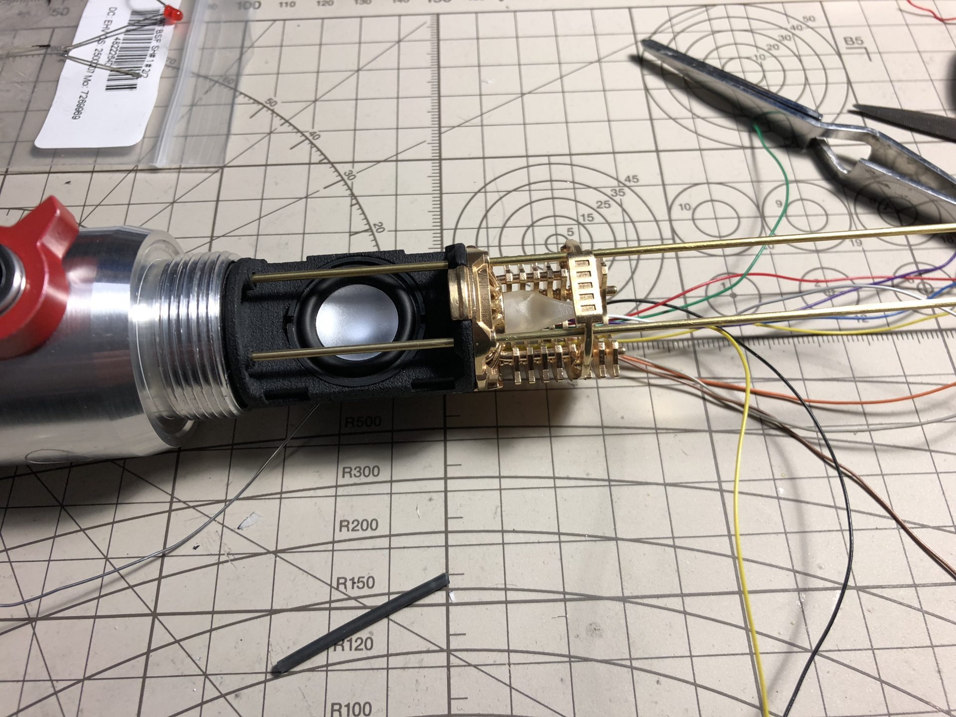
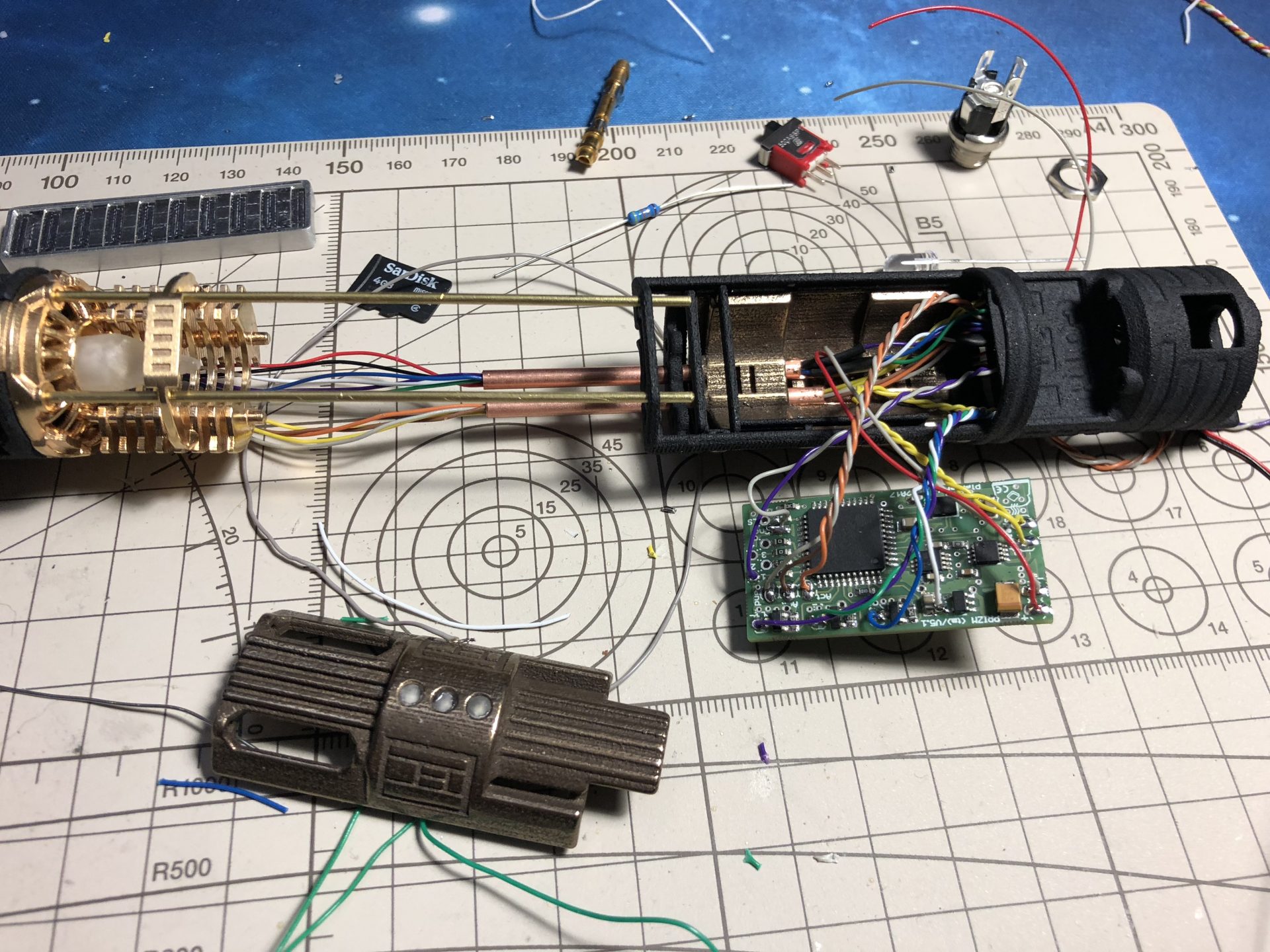
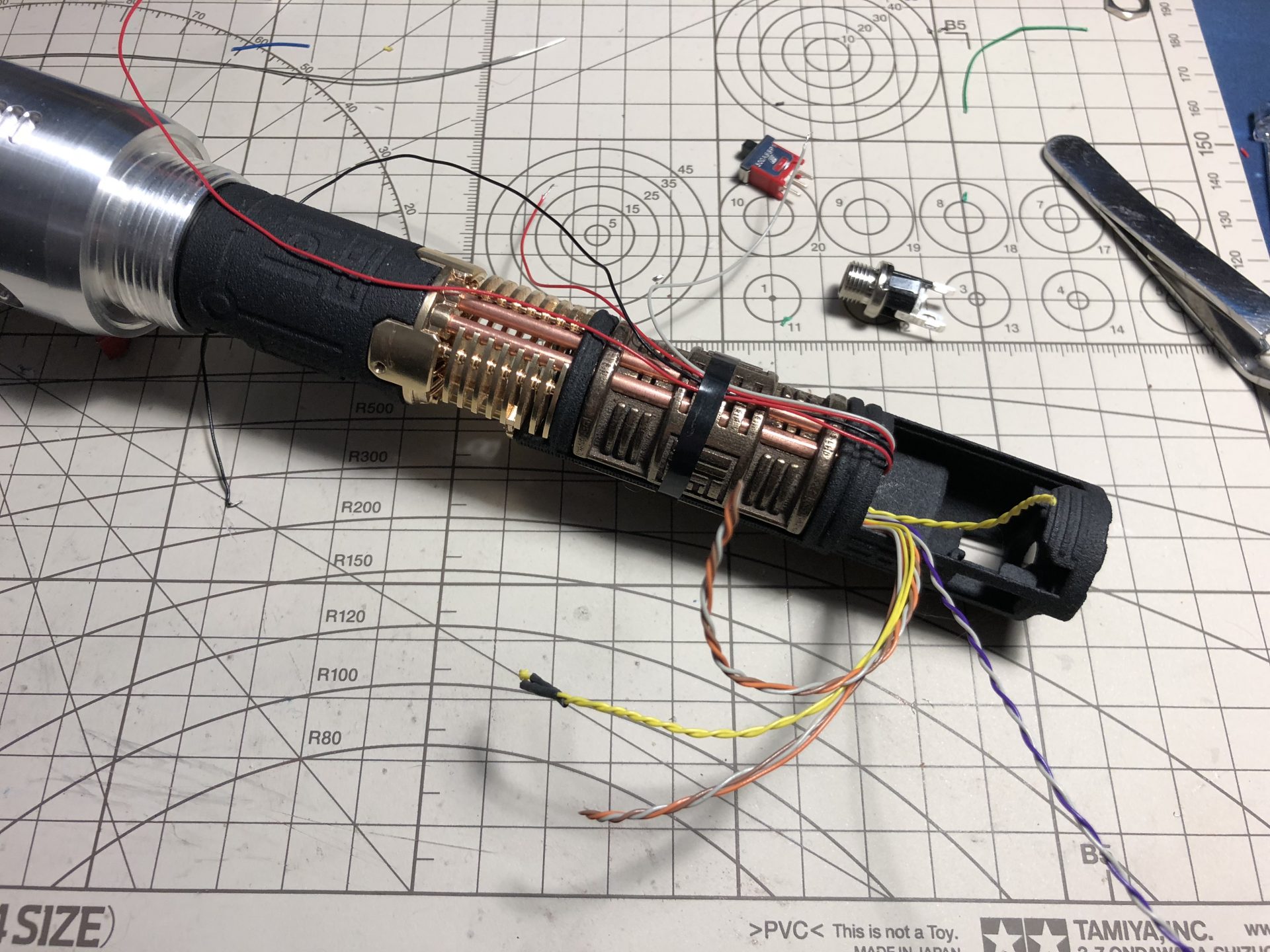
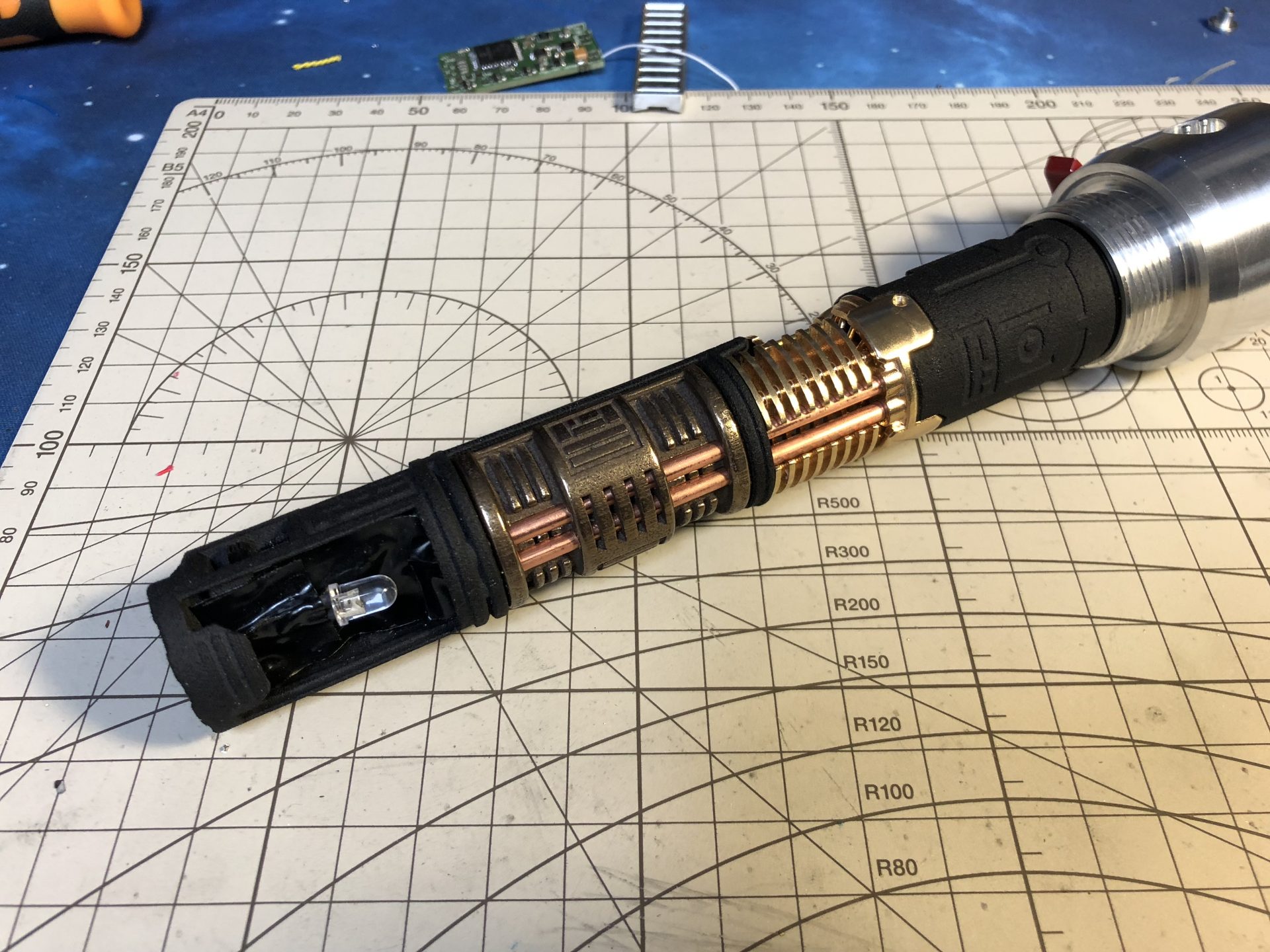
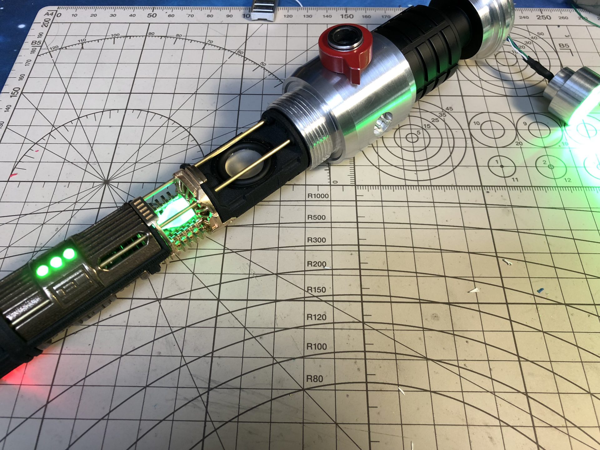
Step 2: Crystal Chamber install
Cut the 1.5mmOD rods and 3mmOD Tube to the right length.
If the cover are printed in steel, some sanding and hole cleaning might be required. Then install the 2 tubes and the bottom cover as shown below.

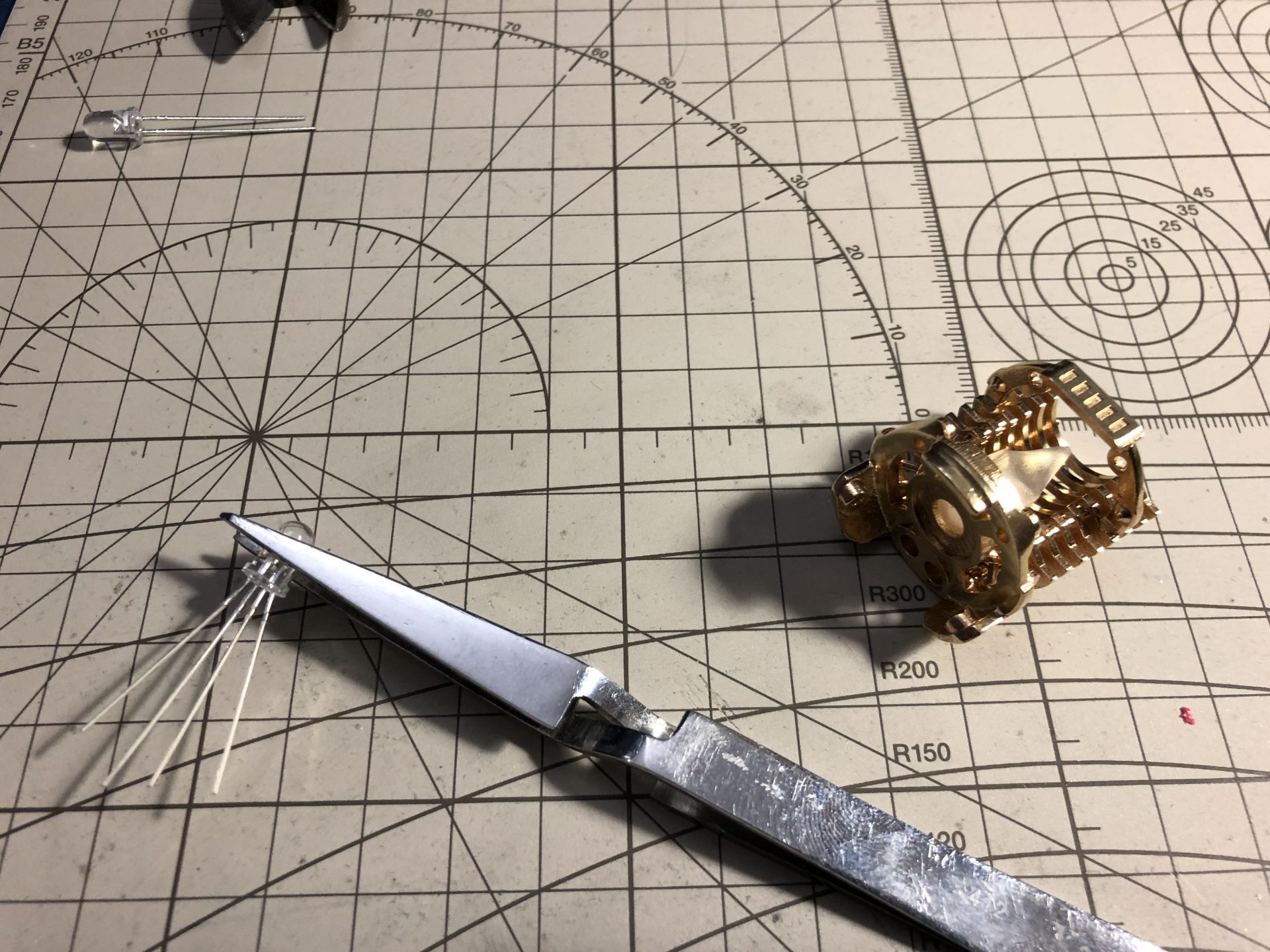
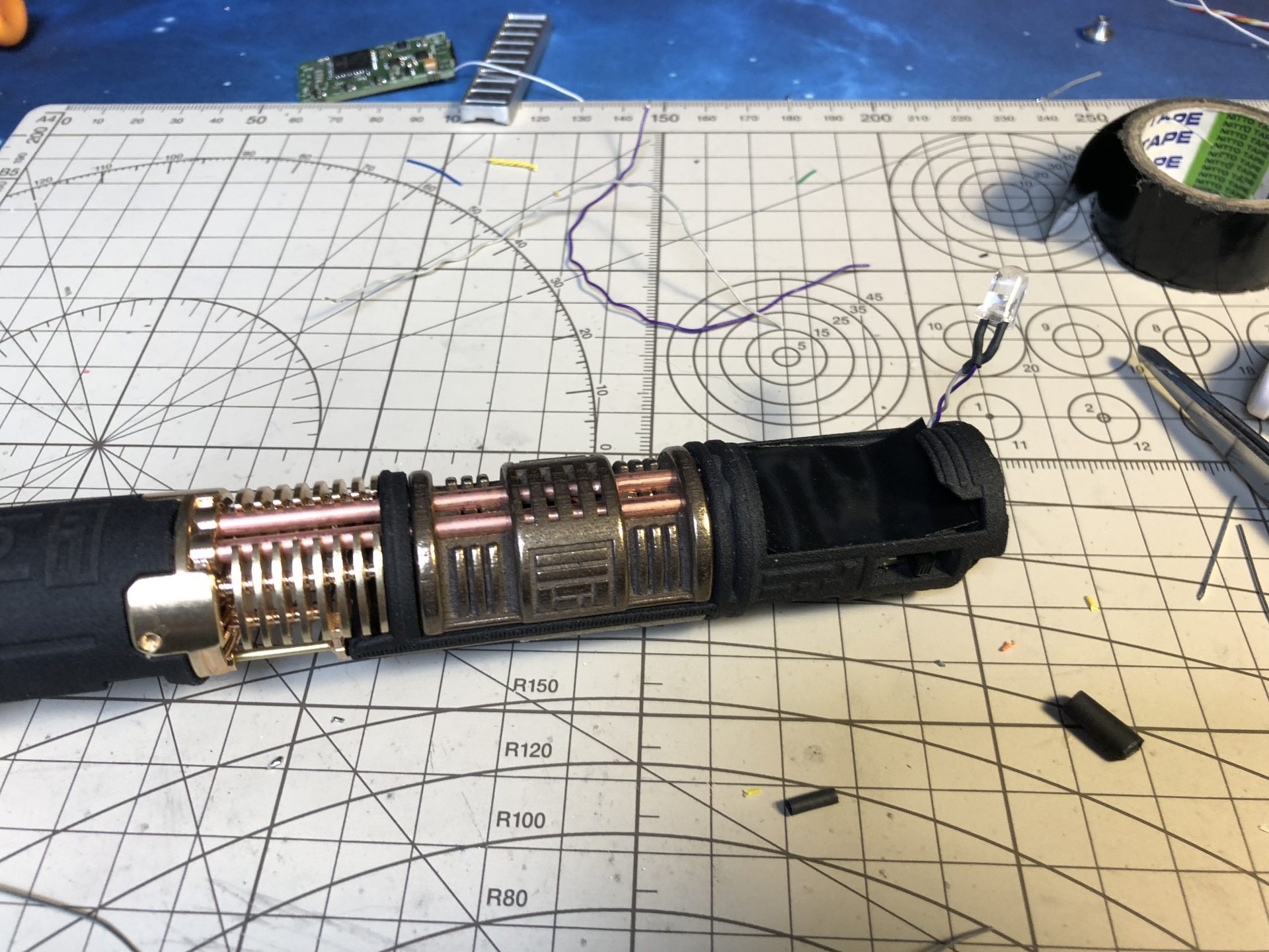
Wire and install the 5mm Crystal accent led and its crystal into the Crystal Chamber part.
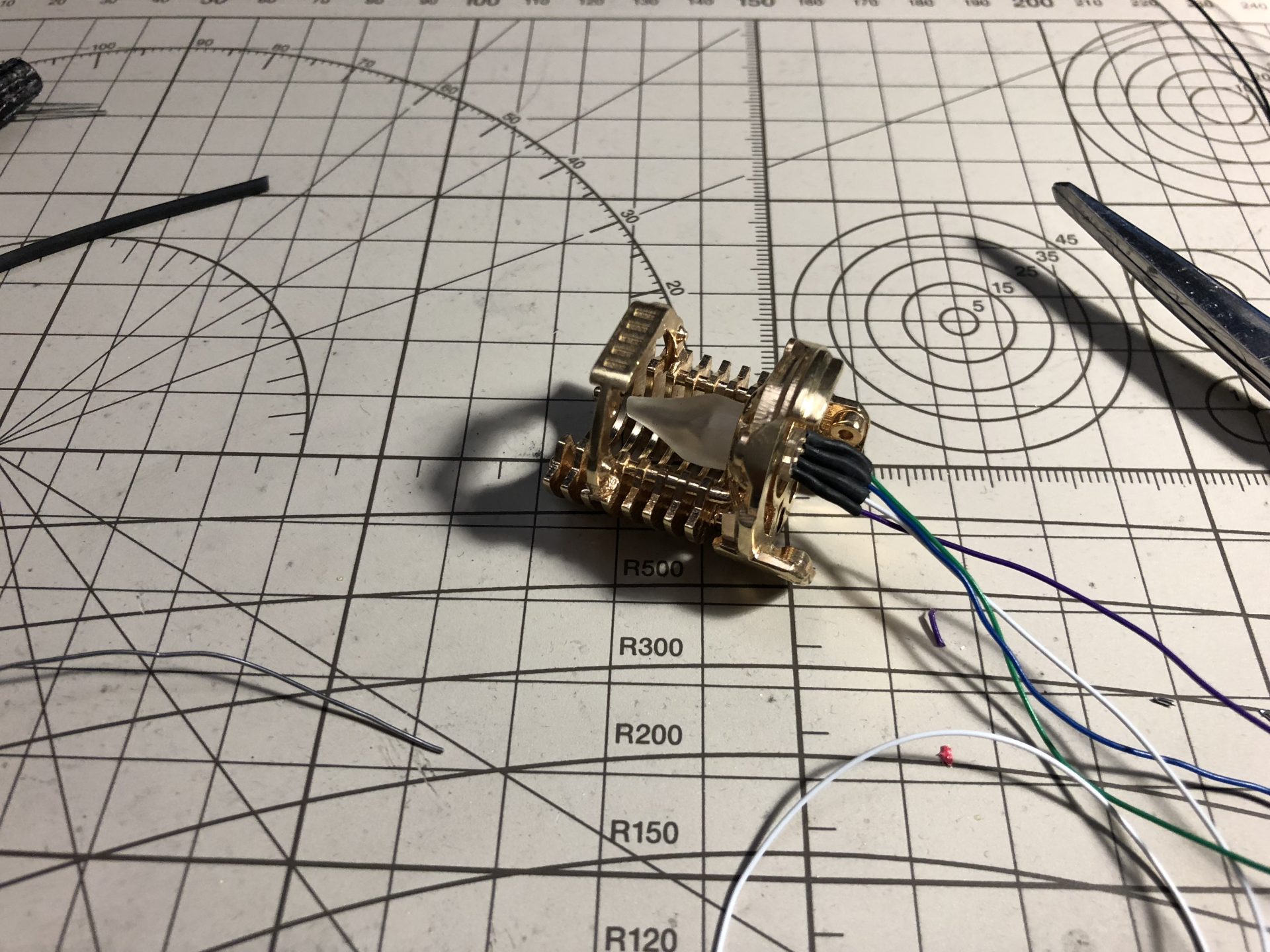
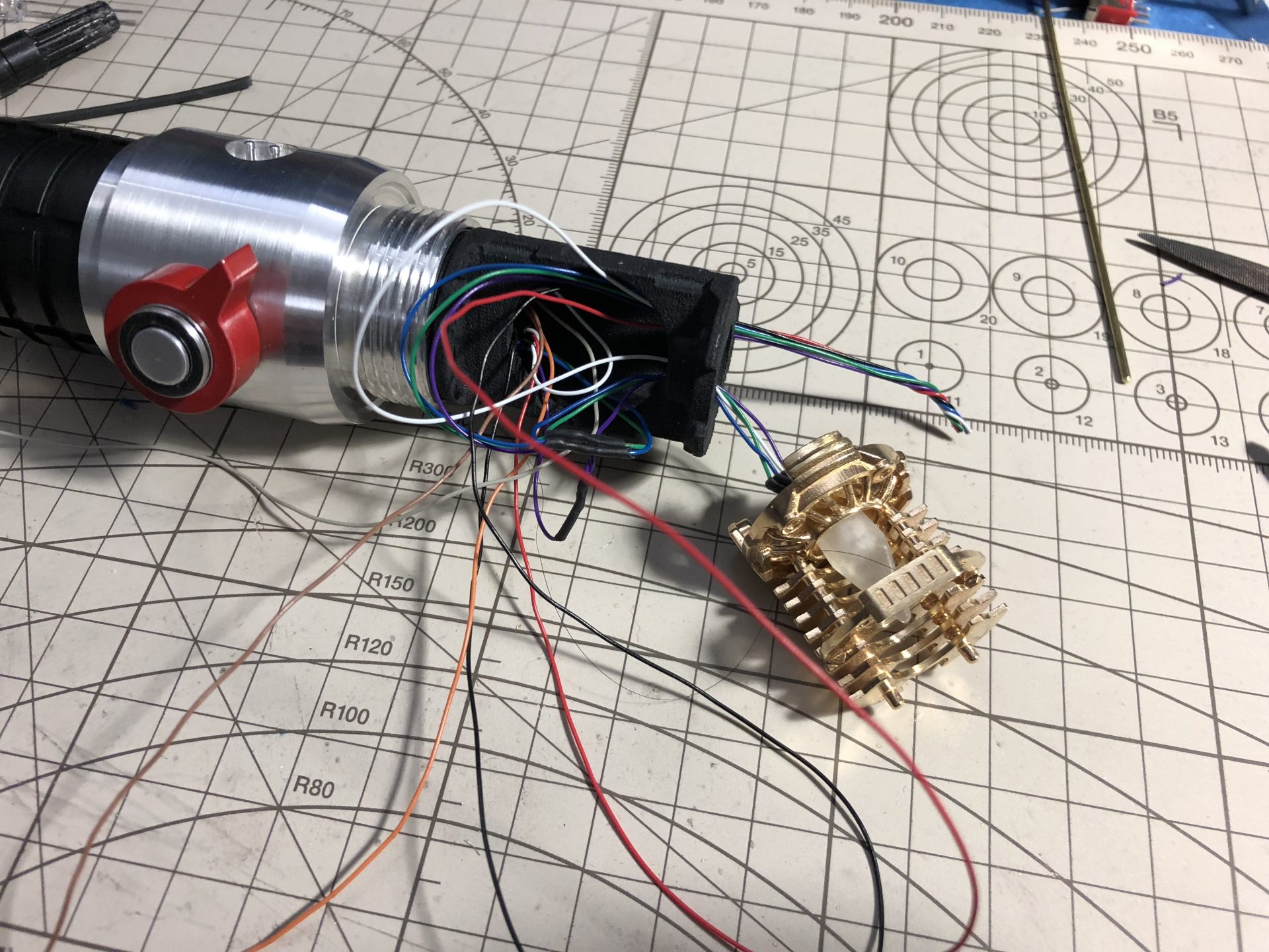
Attach the Crystal Chamber part to the upper chassis.
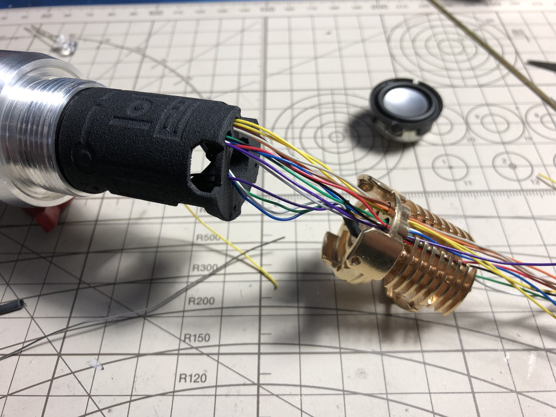
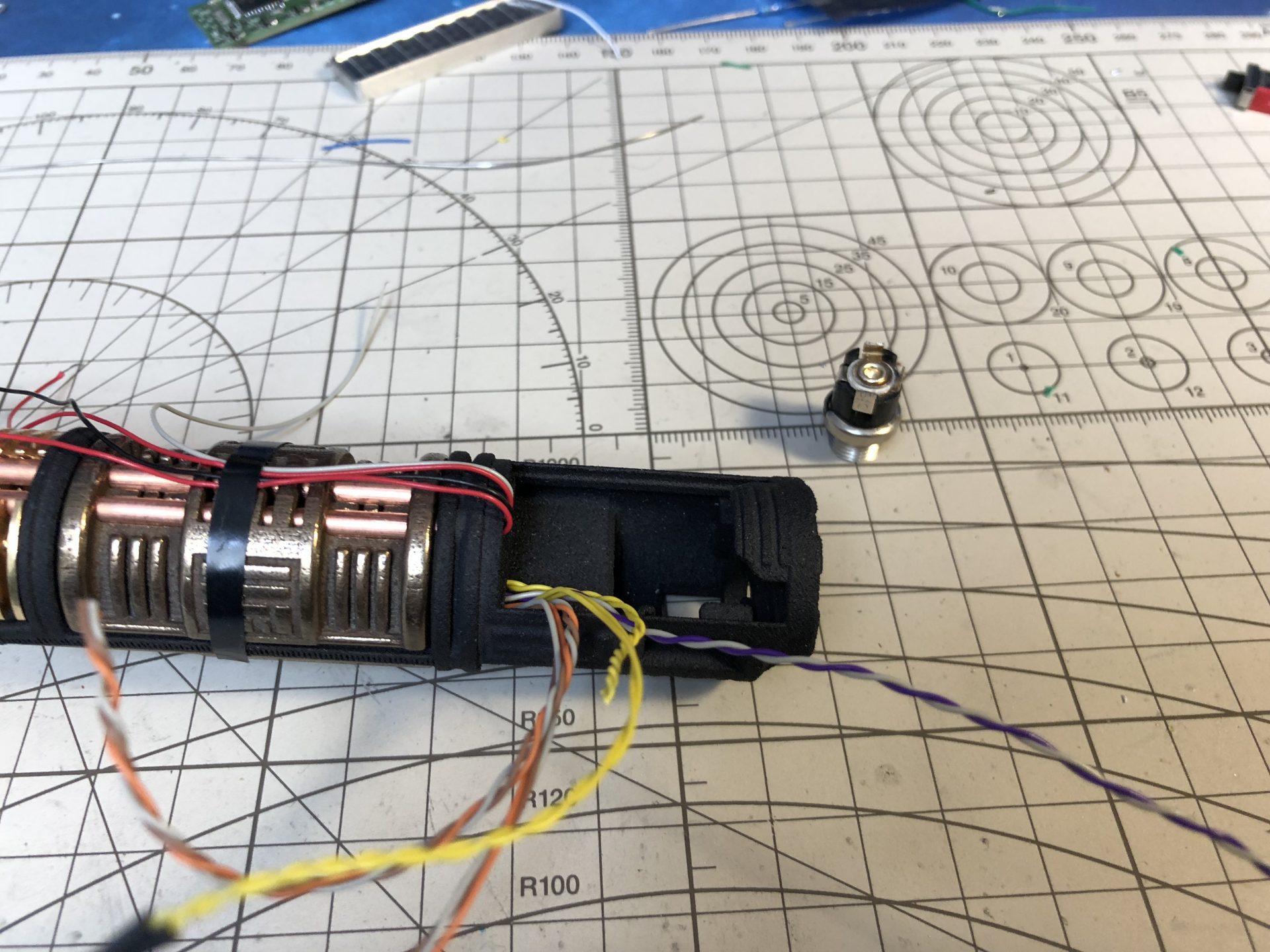
Note that the wires must go through the two 3mm Tubes, so it is mandatory to distribute them evenly and ensure they will slide in without blocking (don’t forget the speaker wires and do not twist the wires to save space).
To limit the number of wires going through the tubes, the crystal chamber LED wires are wired in parallel of the main led under the speaker.
(If there isn’t enough space, the chassis parts can be modded for a bigger wire hole and wire sleeves could be used instead of tubes).
The Crystal Chamber par can be glued to the upper chassis for extra security. A 1.5mmOD rod can also be optionally added sideways to lock both part together.
Once attached together, make room for the speaker / secure the wires.
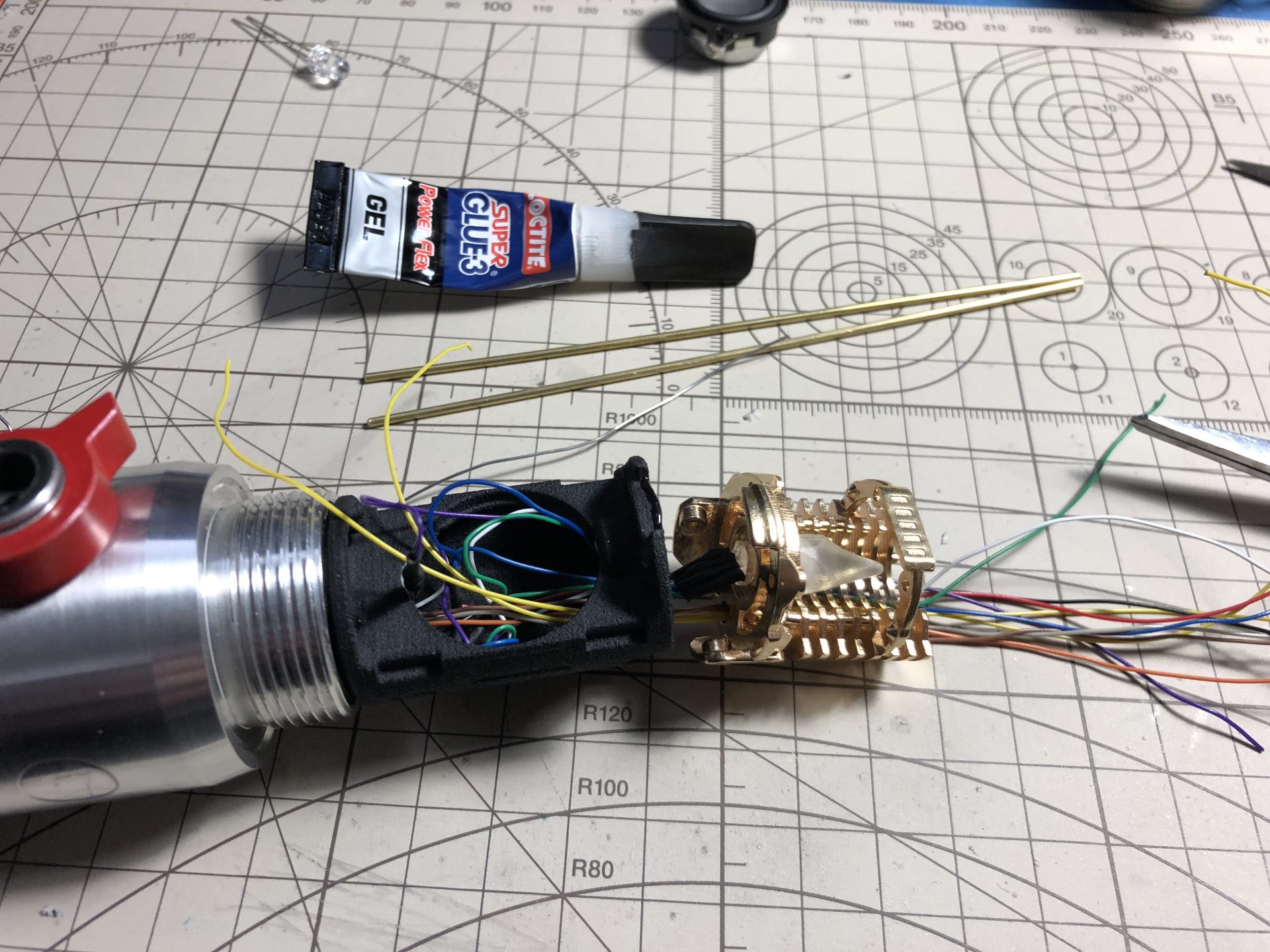
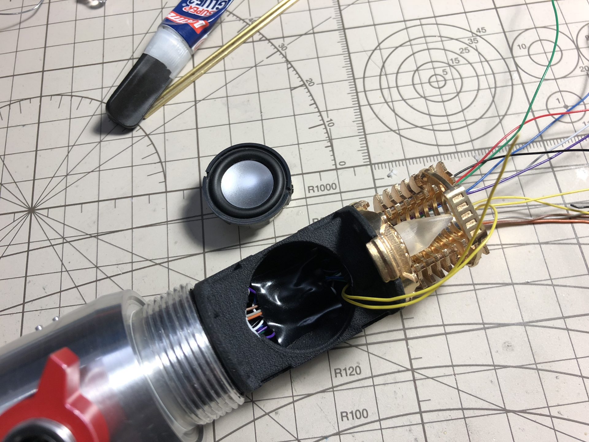
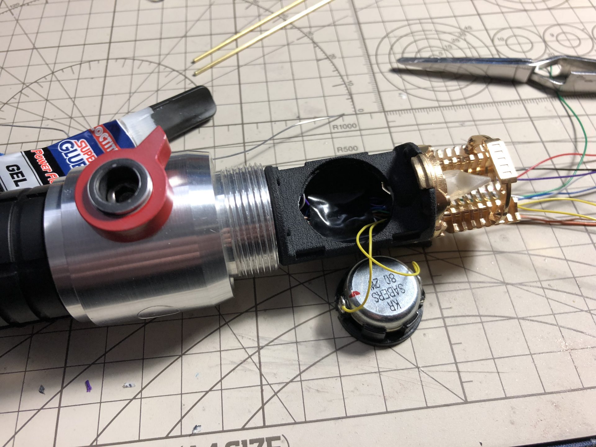
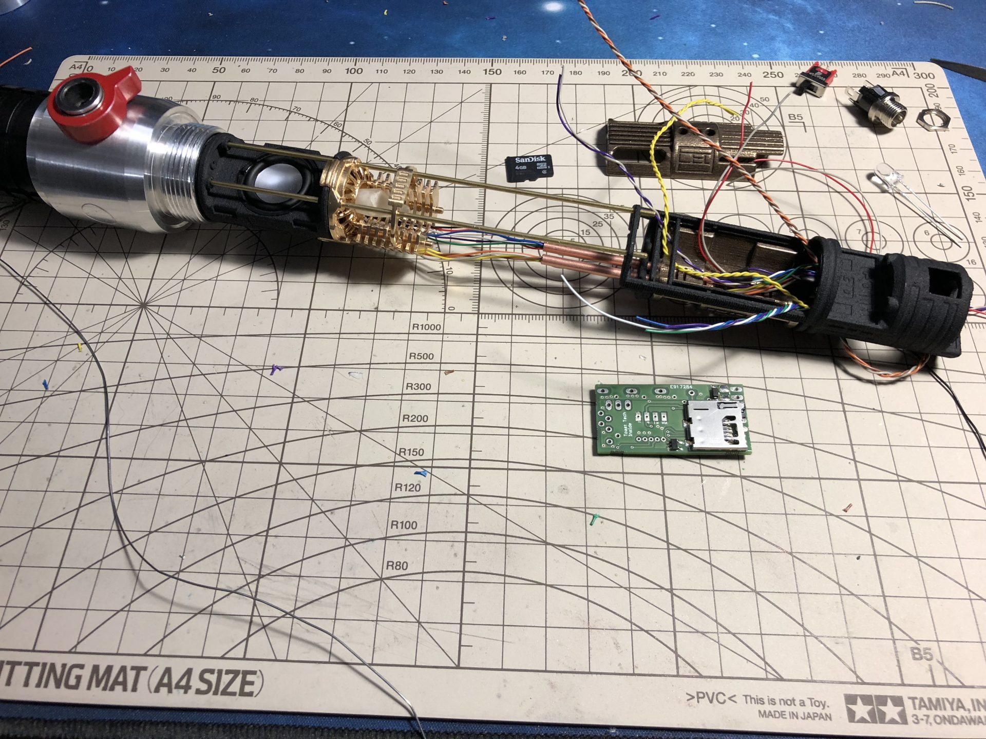
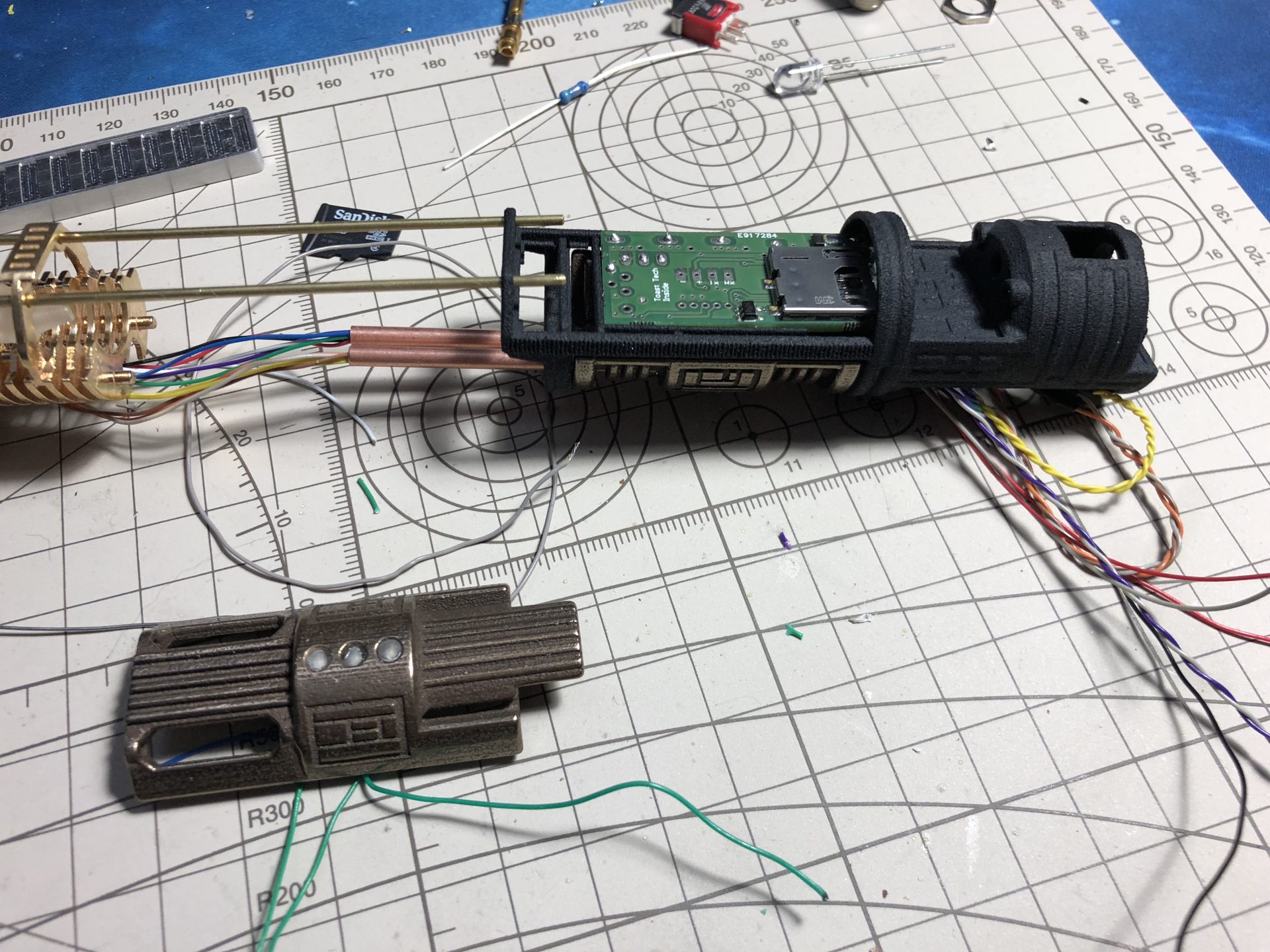
Step 3: Speaker and soundboard install
Wires and install the speaker in its slot (bits of super glue are used to secure the speaker in).
Then add the two 1.5mmOD rods as shown below, and glue them for security.
Three 3mm accent led can be optionally added to the top soundboard cover
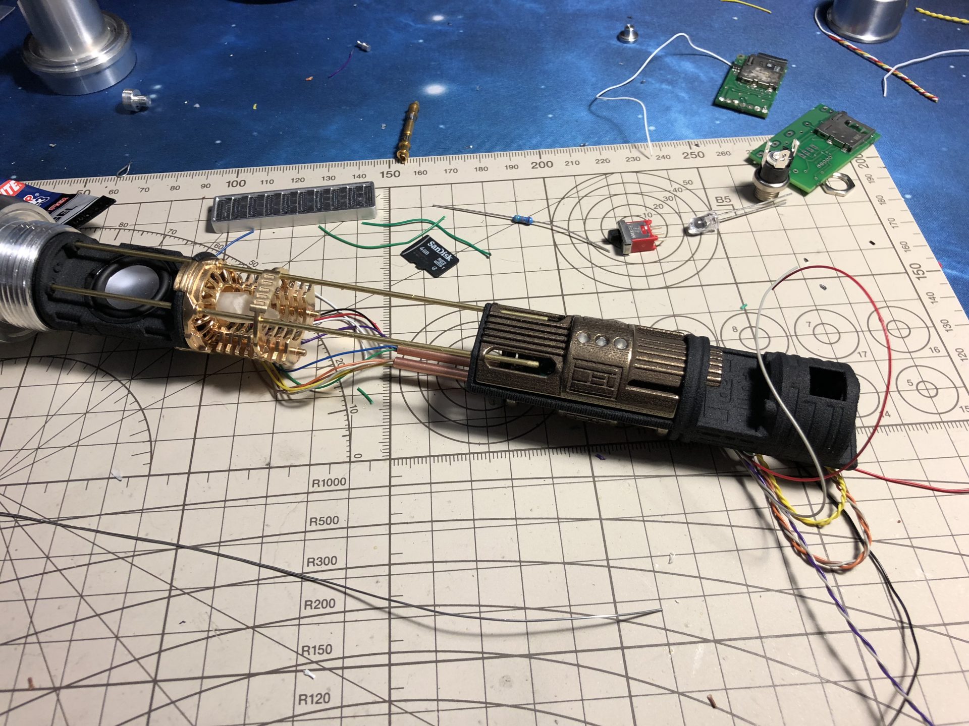
Pass the wires through the tube up to the back of the soundboard chassis module.
It will be easier here to wires the soundboard with another set of wires and connect everything later from the back of the chassis (read the following step to understand why).
Eventually add the cover over the soundboard area.
Gently / slowly pull the front chassis wires from the back to slide and join the chassis together (glue the rods and tubes with tiny bit of super glue, not too much, just enough to secure the assembly).
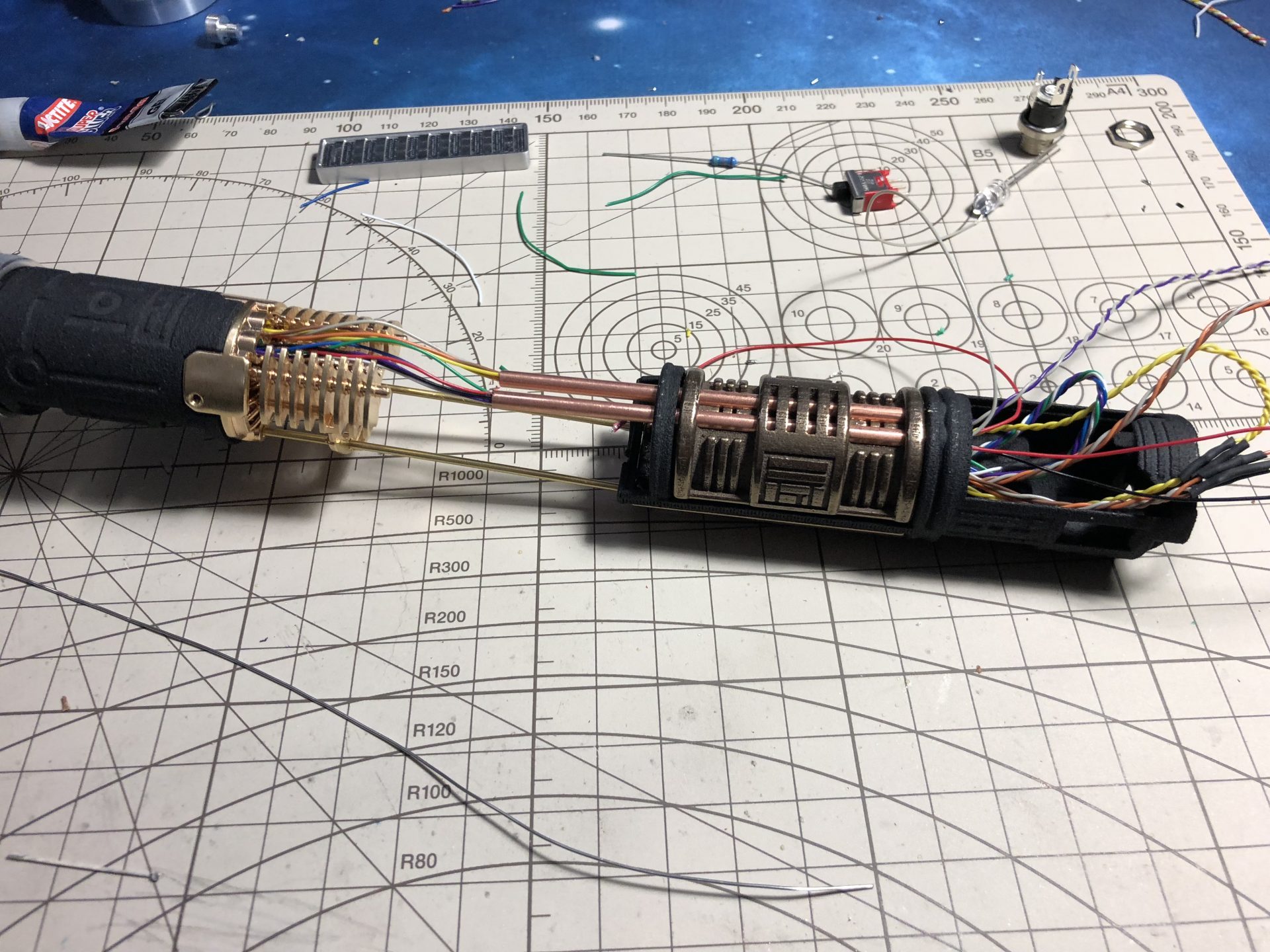
Step 4: Recharge port, Switch and finishing the soundboard install
Cut the recharge port leads to their minimum, then wire it and add it to its dedicated slot (the hex nut is used to lock the port).
Pass the negative soundboard wire through the on/off switch hole area and wire the switch.
The switch once placed in its slot needs to be glued.
Solder all the wires together (after cutting a bit of length). The wires can either be push back under the soundboard or hidden in the back.
(note we have also added an 4th accent led on the back).
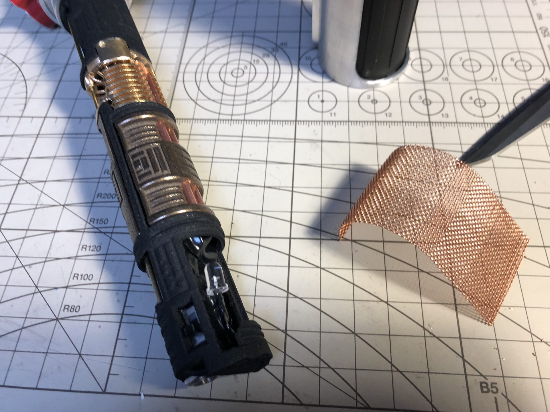
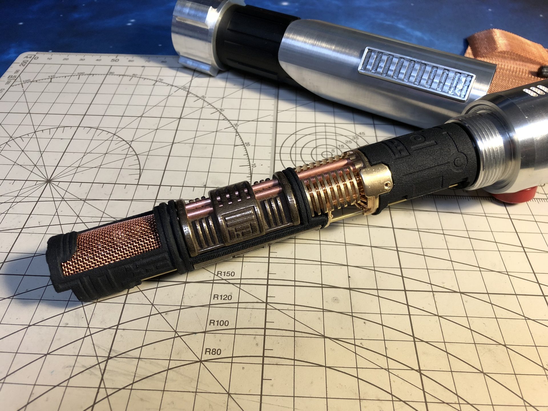
Optionally add mesh over the back (CEx area)
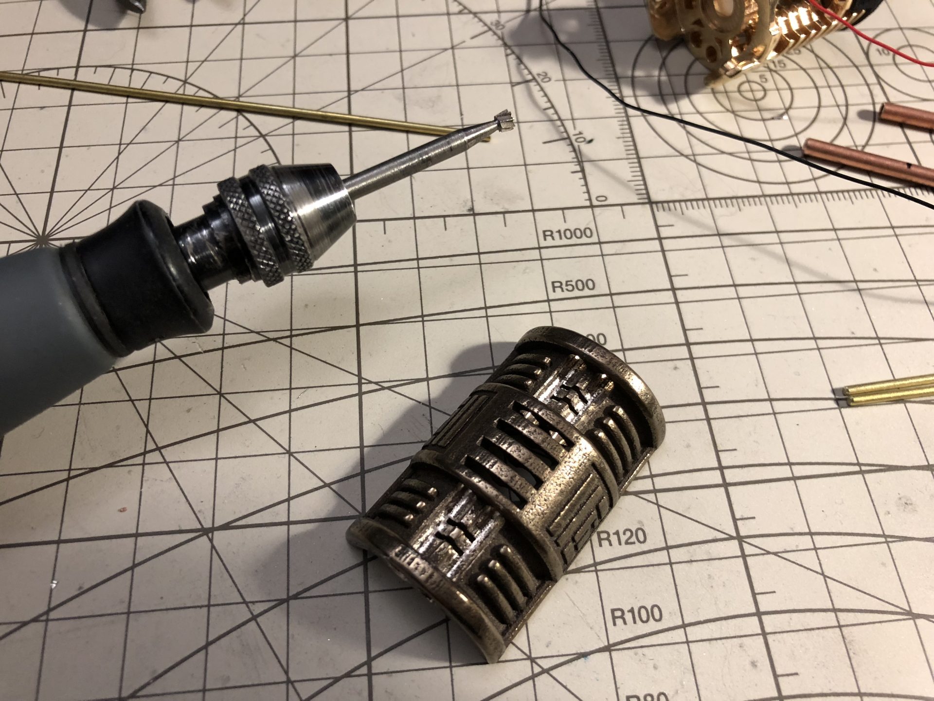
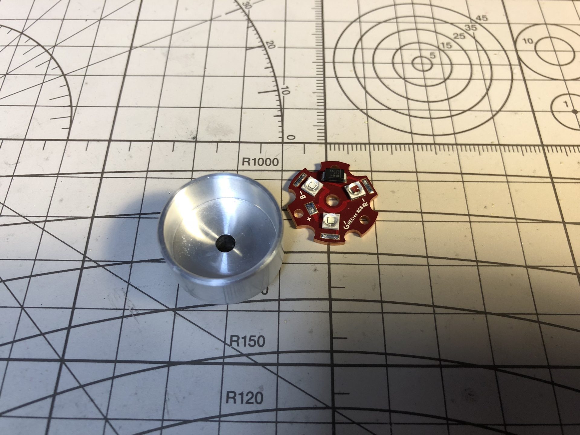
Step 5: Led and blade install
Sand the led and optic surroundings to fit properly into the heatsink. Make sure everything is tested ok.
then epoxy the heatsink in the emitter, using the blade part to guide the heatsink in. Make sure not to use to much glue and not put glue where the blade part inserts.
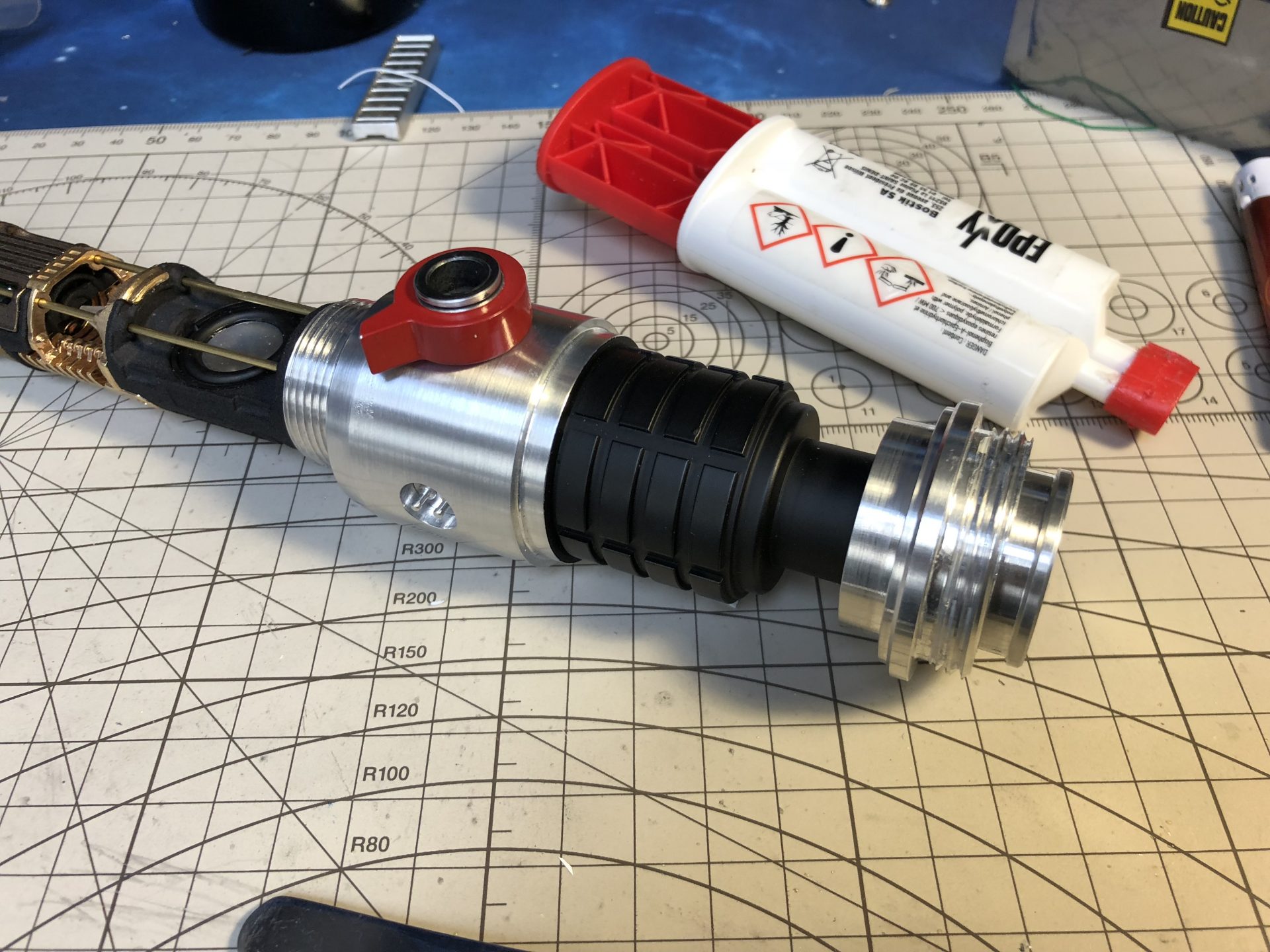
Epoxy the blade part to the blade (there is little space for that, make sure to measure the depth properly).