These designs are no longer supported (FAQ)
Master Chassis:
⇒ Part 1 – Main Chassis
Style1 (28mm flat speaker) => korbanth-crossguard-2-0-master-part1-style1
Style2 (28mm bass speaker) => korbanth-crossguard-2-0-master-part1-style2
⇒ Part 2 – CC insert 1 => korbanth-crossguard-2-0-master-part2
⇒ Part 3 – CC insert 2 => korbanth-crossguard-2-0-master-part3
⇒ Part 4 – CC insert 3 => korbanth-crossguard-2-0-master-part4
⇒ Part 5 – CC insert 4 => korbanth-crossguard-2-0-master-part5
⇒ Part 6 – CC insert 5 => korbanth-crossguard-2-0-master-part6
⇒ Part 7 – Optional Crystal => korbanth-crossguard-2-0-master-part7
3- Accessories:
The plastic parts provided with the hilt can be replaced by the following accessories (available in metal)
⇒ Pommer insert – Optional pommel insert replacement: korbanth-crossguard-2-0-pommel-insert

⇒ Emitter inserts – Optional emitter inserts replacement:
Style1 (Dremel Required, parts joined together to reduce cost in metal) – korbanth-crossguard-2-0-emitter-inserts-style1
Style2 (Install Ready, available in Steel only) – korbanth-crossguard-2-0-emitter-inserts-style2

3- Additional chassis parts:
The Master Chassis requires the following parts:
⇒ 1.5mmOD rods for the CC assembly
⇒ 1mmOD rods for the CC Insert 2 (Optional)
⇒ 2mmOD rod + two 1mmx2mmOD magnets for the Aux switch assembly (Optional)
Quick Install Guide:
Disclainer:
– These instructions will details the install procedure as much as possible. GOTH-3Designs cannot be held responsible for any mistakes made by DIYers.
– Always wear protective gear when working on install (gloves, eye protection, …), GOTH-3Designs cannot be held responsible in case of accident.
Note 1: 30awg wires and smaller are mandatory for most of our chassis (if neopixel, 32awg is mandatory for switches, accent leds, … to compensate bigger main blade and battery wires).
Note 2: These instructions will not cover how to wire the soundboard, make sure to learn how to by reading the manual.
Note 3: Recharge port wiring reminder:

Note 5: MultiBoards Adaptive Chassis:
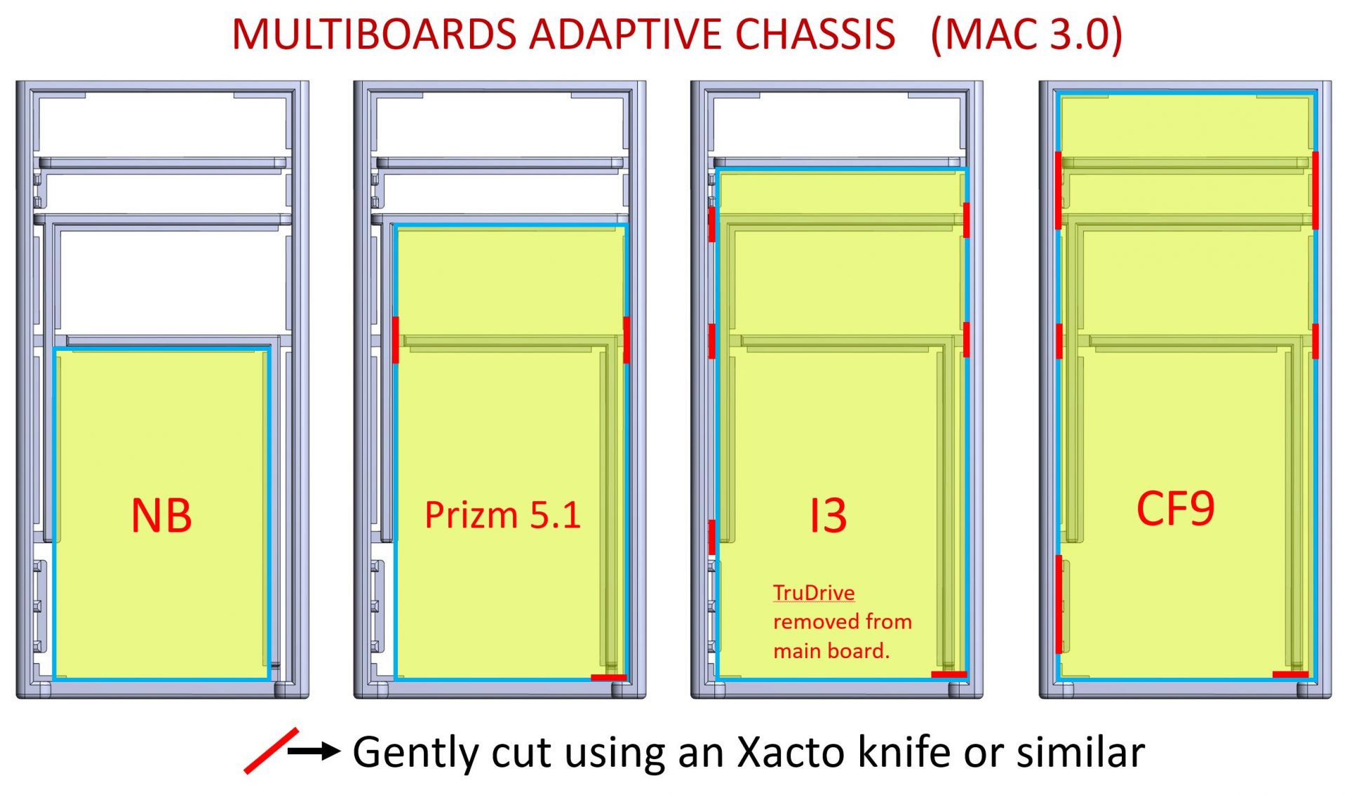
(CF9 isn’t compatible with Master Chassis Part1 Style2 and Padawan chassis Var1 Style2)
Hilt modifications
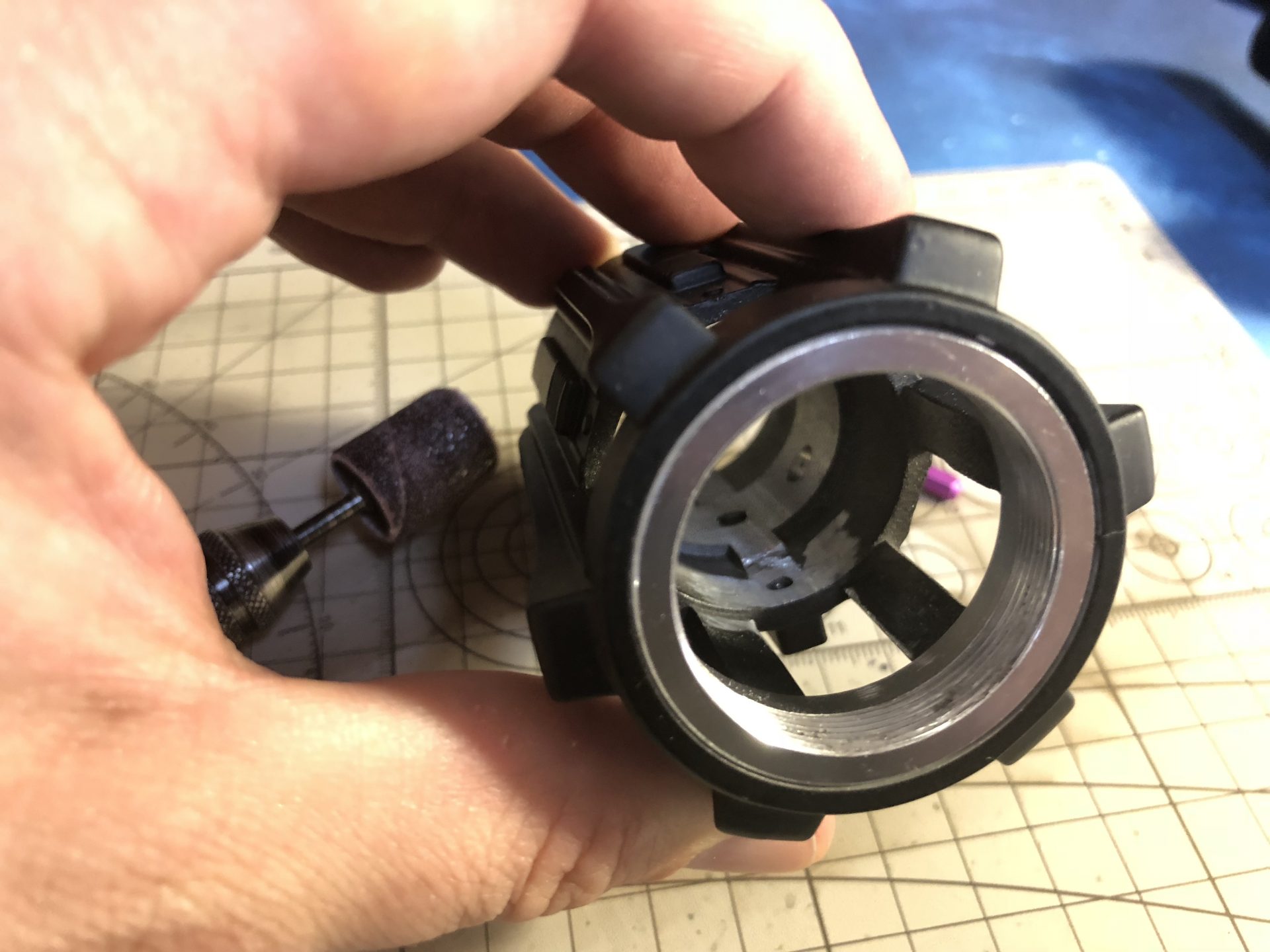
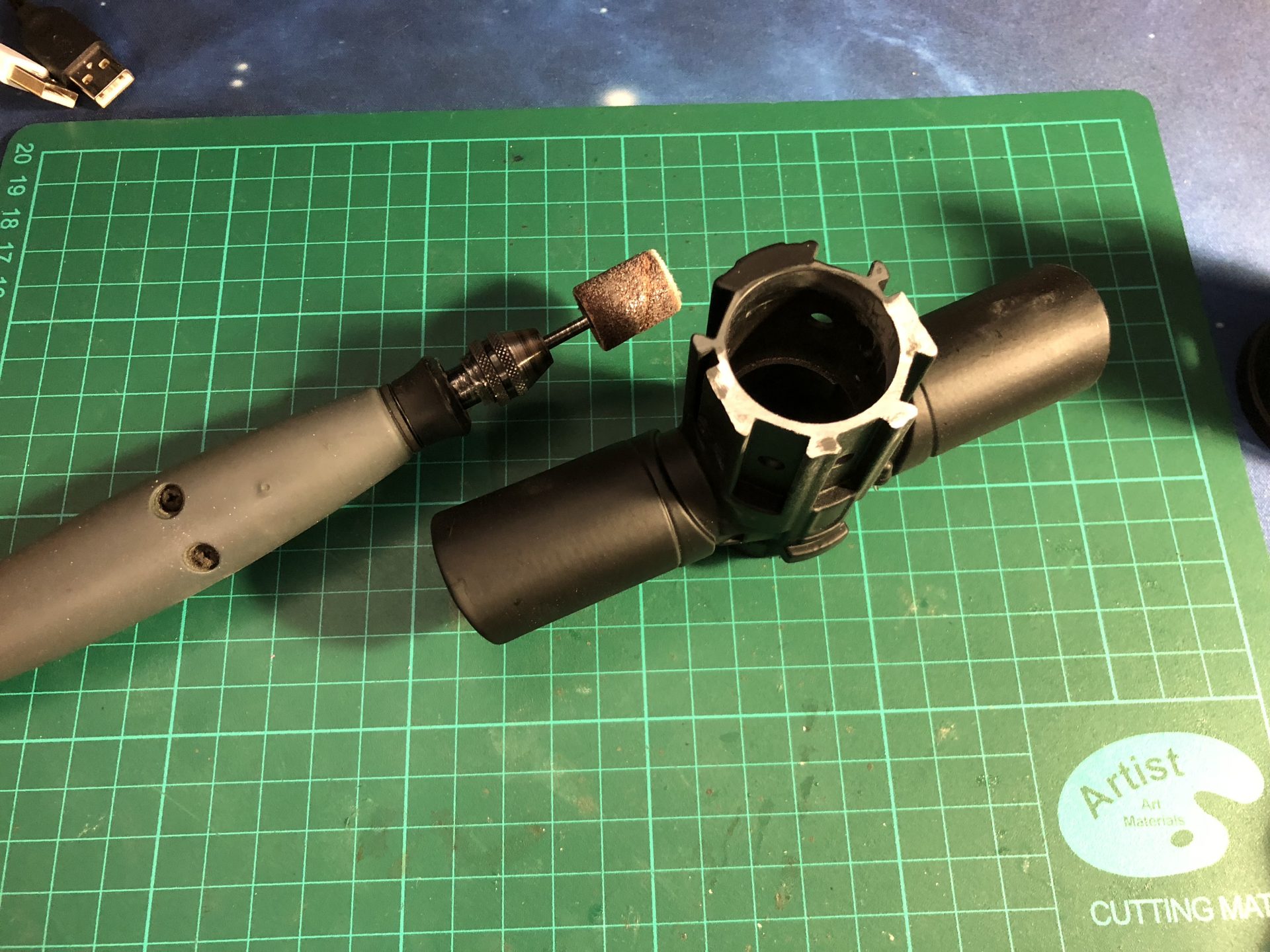
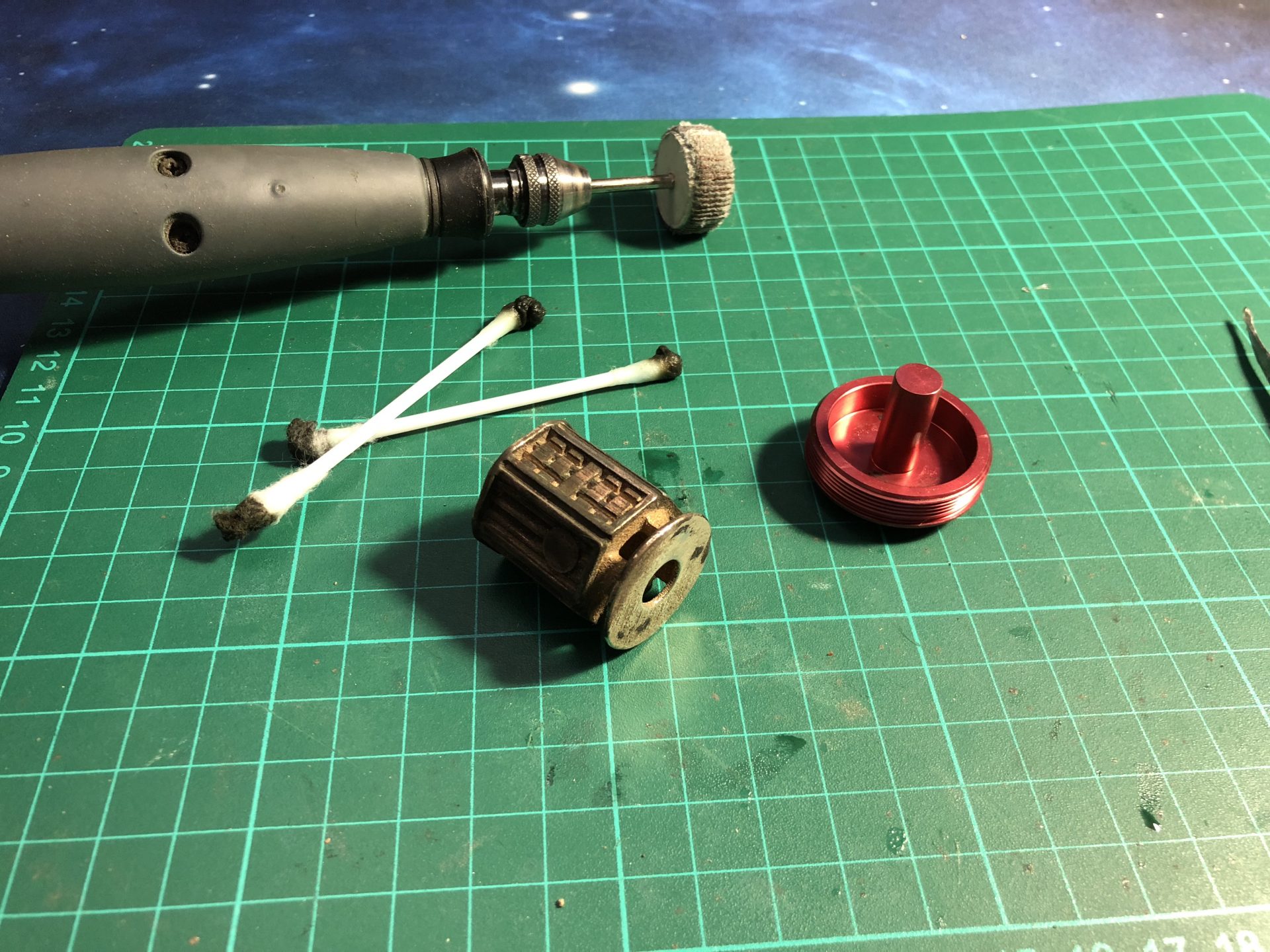
1) In order for the speaker holder to fit, sanding is required as shown below (using a Dremel sanding drum):
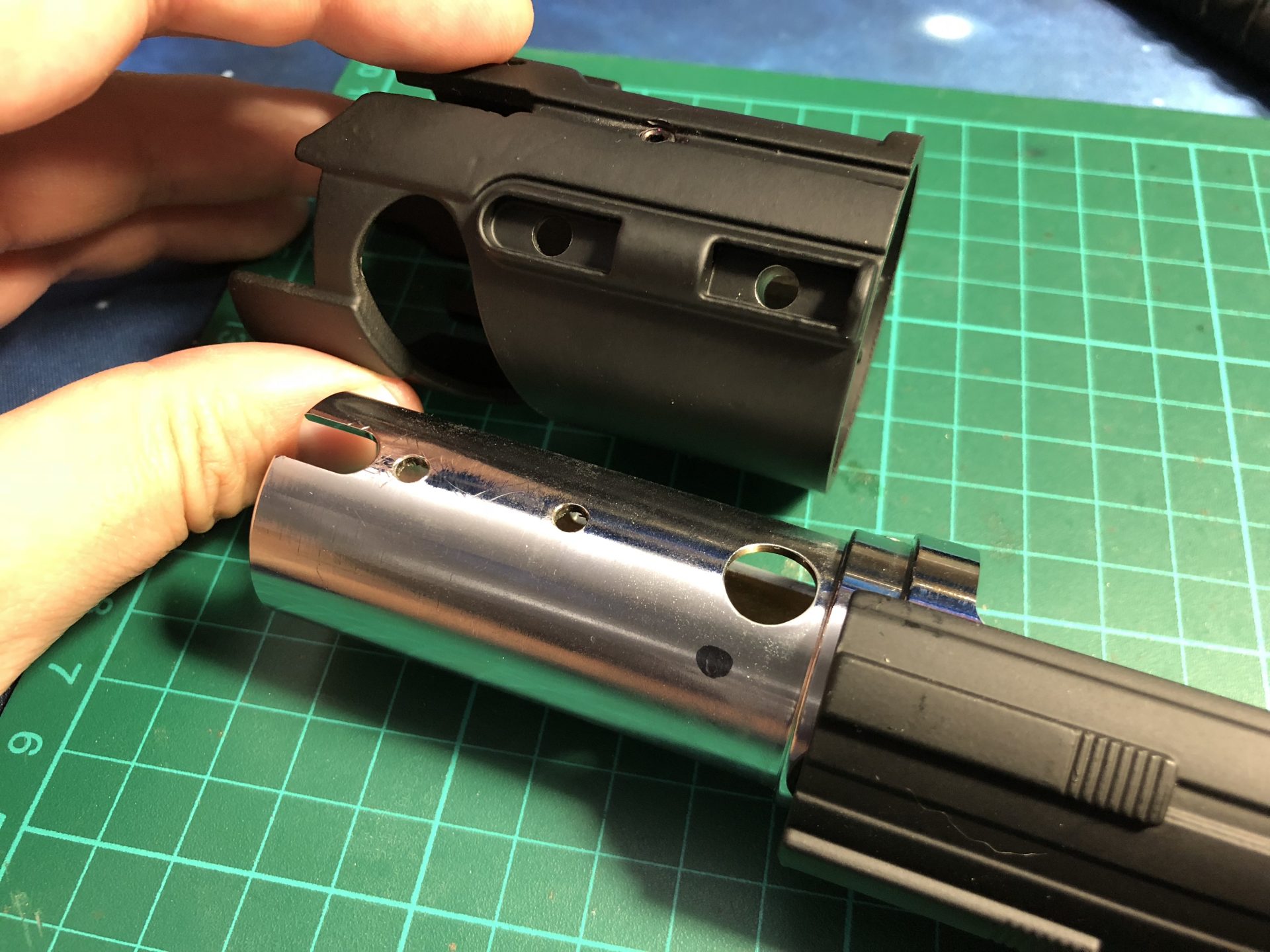
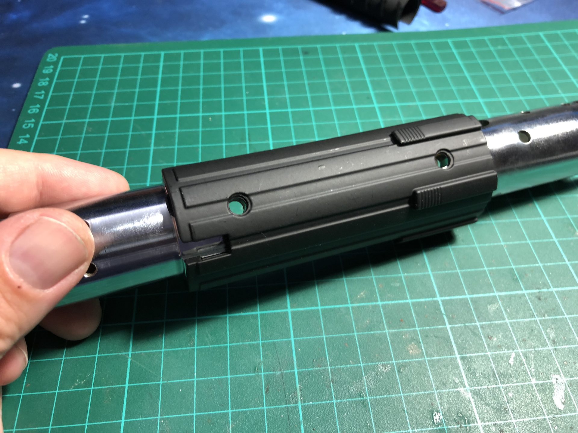
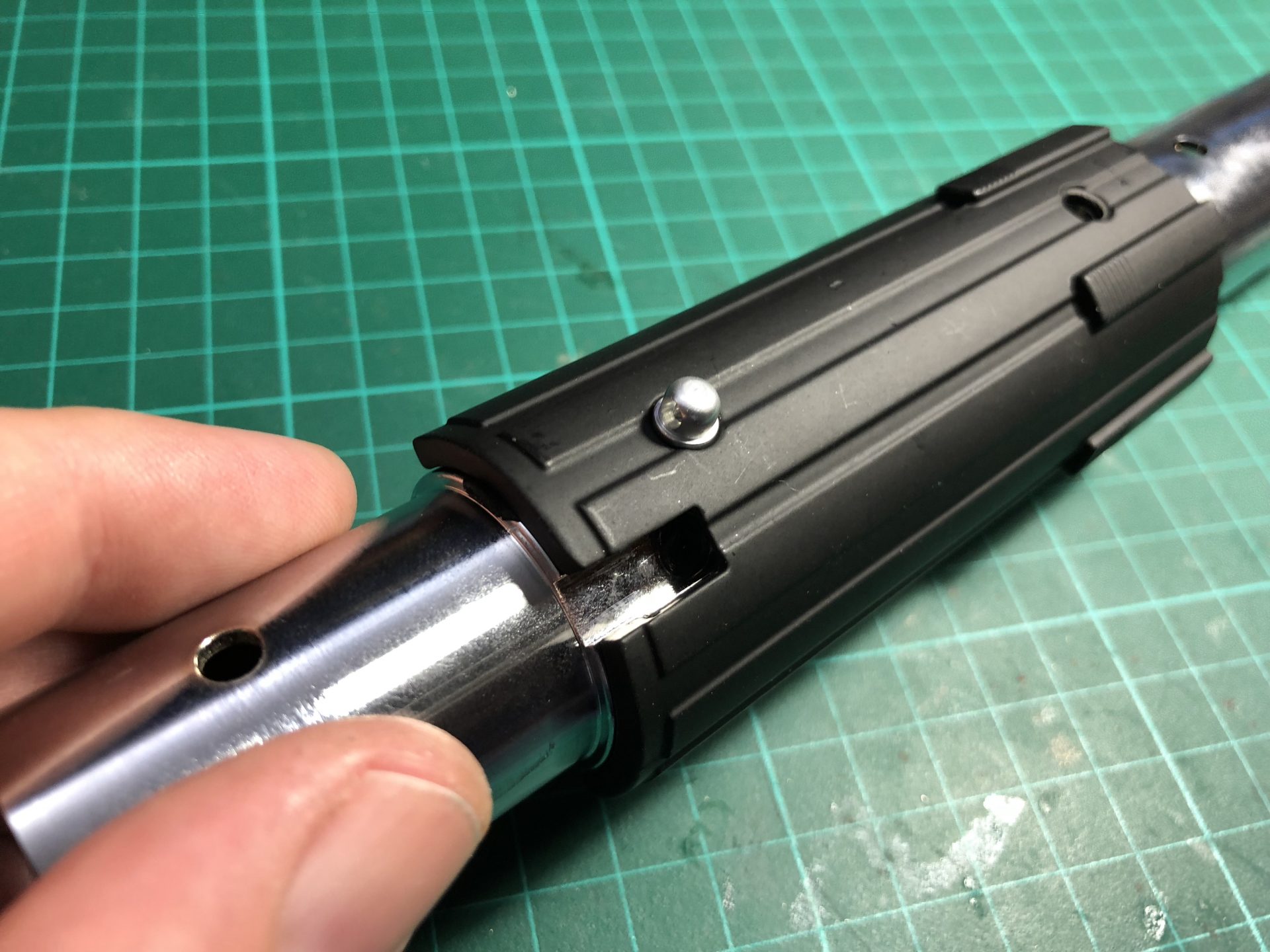
2) There are various possibilities to make the quillons led and main switch install easier. Here is an exemple of mods to the upper shroud and inner tube to ease wires management when inserting the chassis (mandatory when using a Master Chassis).
First, we remove a few mm under the emitter so that the quillon led wires can be joined in the middle instead of being separated on each side.
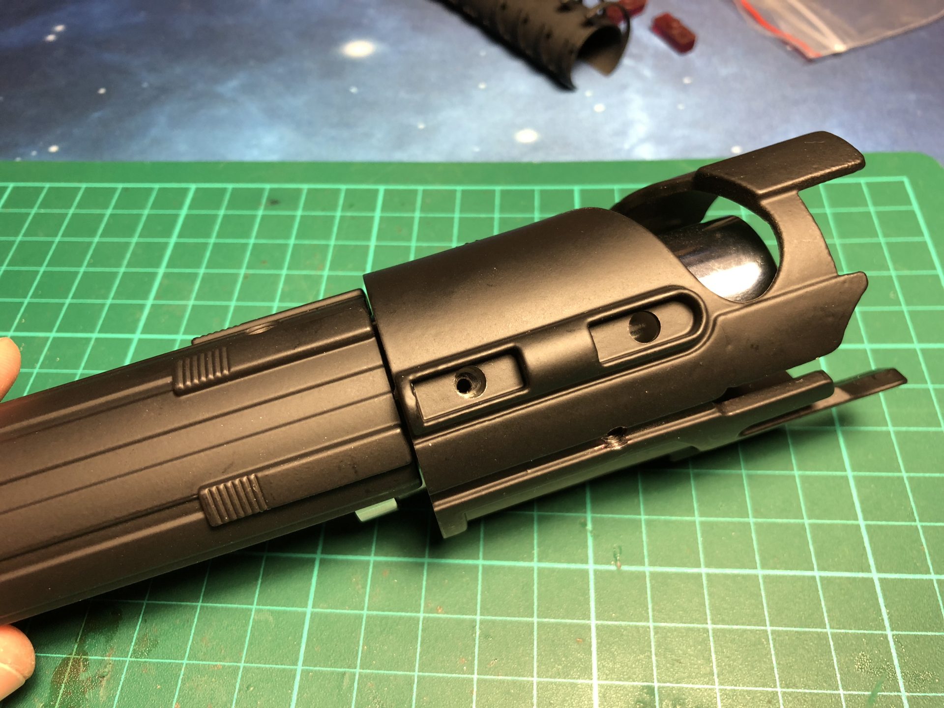
Add a windows in the inner tubes for the wires to pass through, and the same on the shroud.

Finally, add a channel in the shroud, right of the main switch area, to make wire passage easier (as shown below, the right hole is to be used for the main switch wires – mandatory on the master chassis as the battery slot will block the main switch window).
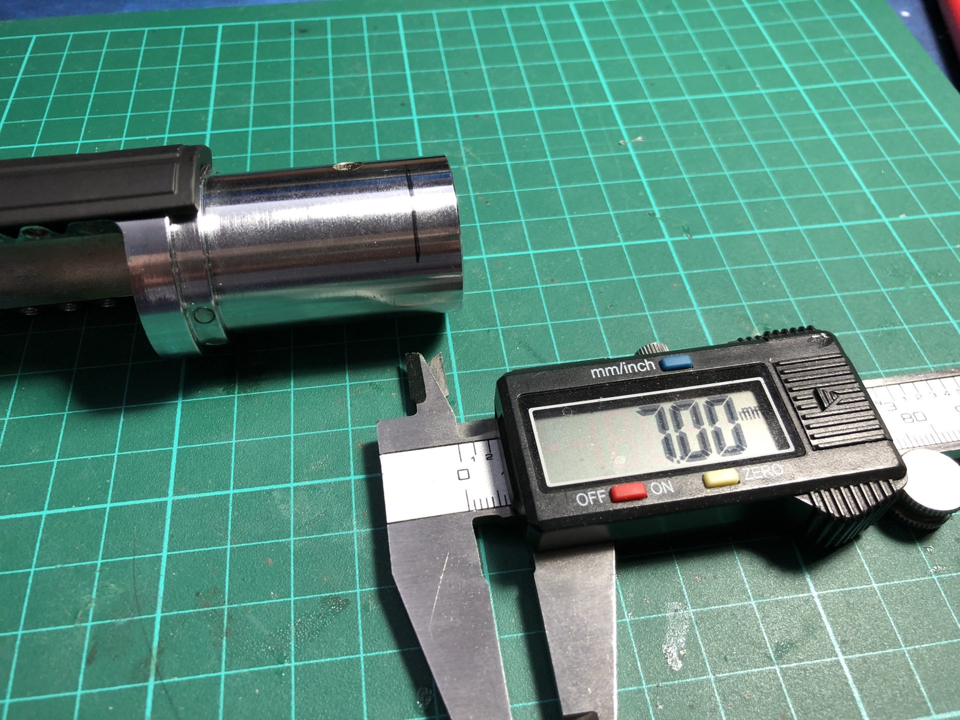
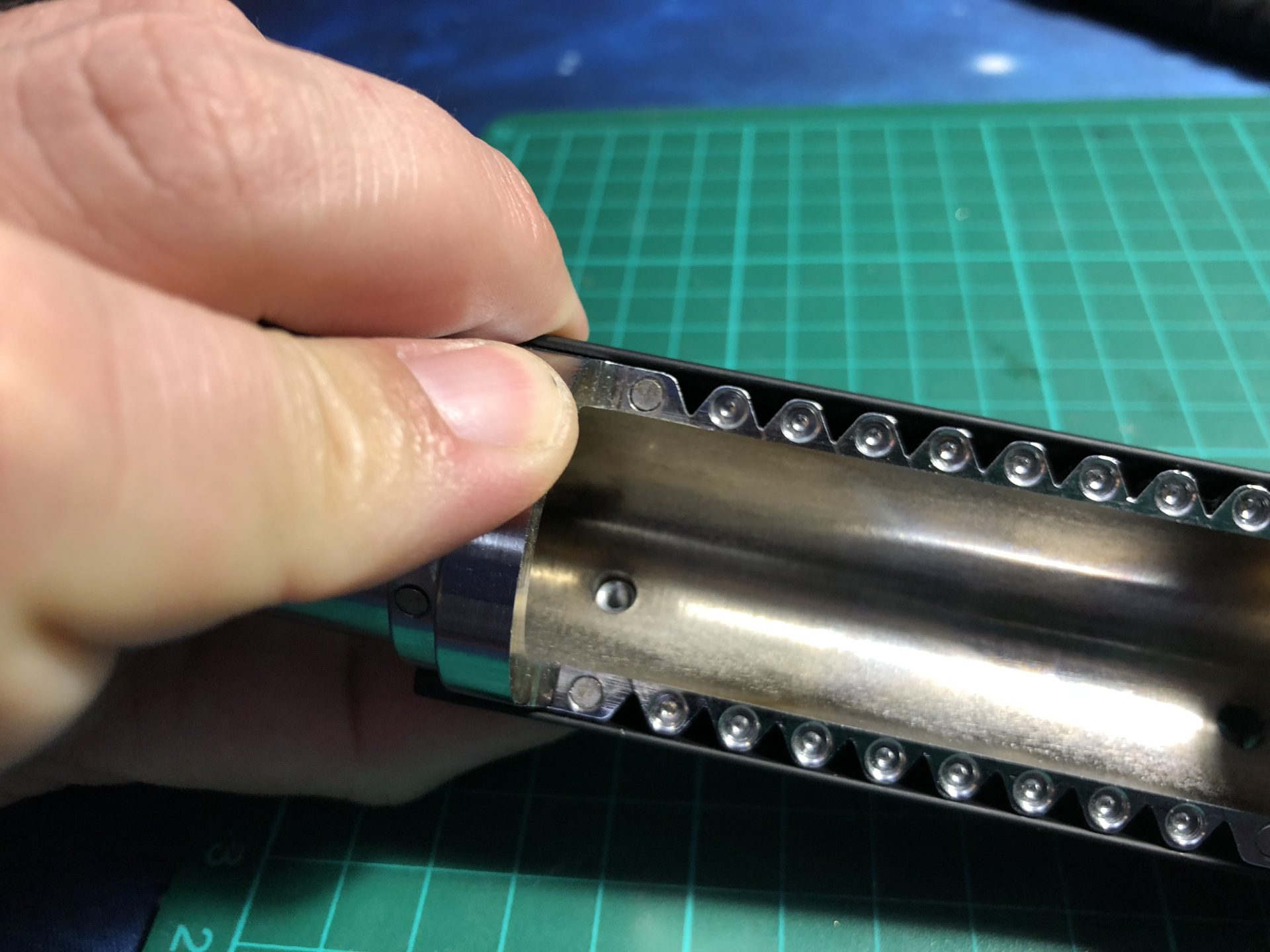
3) If a Style 2 chassis is used (for 28mm bass speaker), the inner tube will have to be cut / remove 7mm length to allow extra space for the speaker holder.
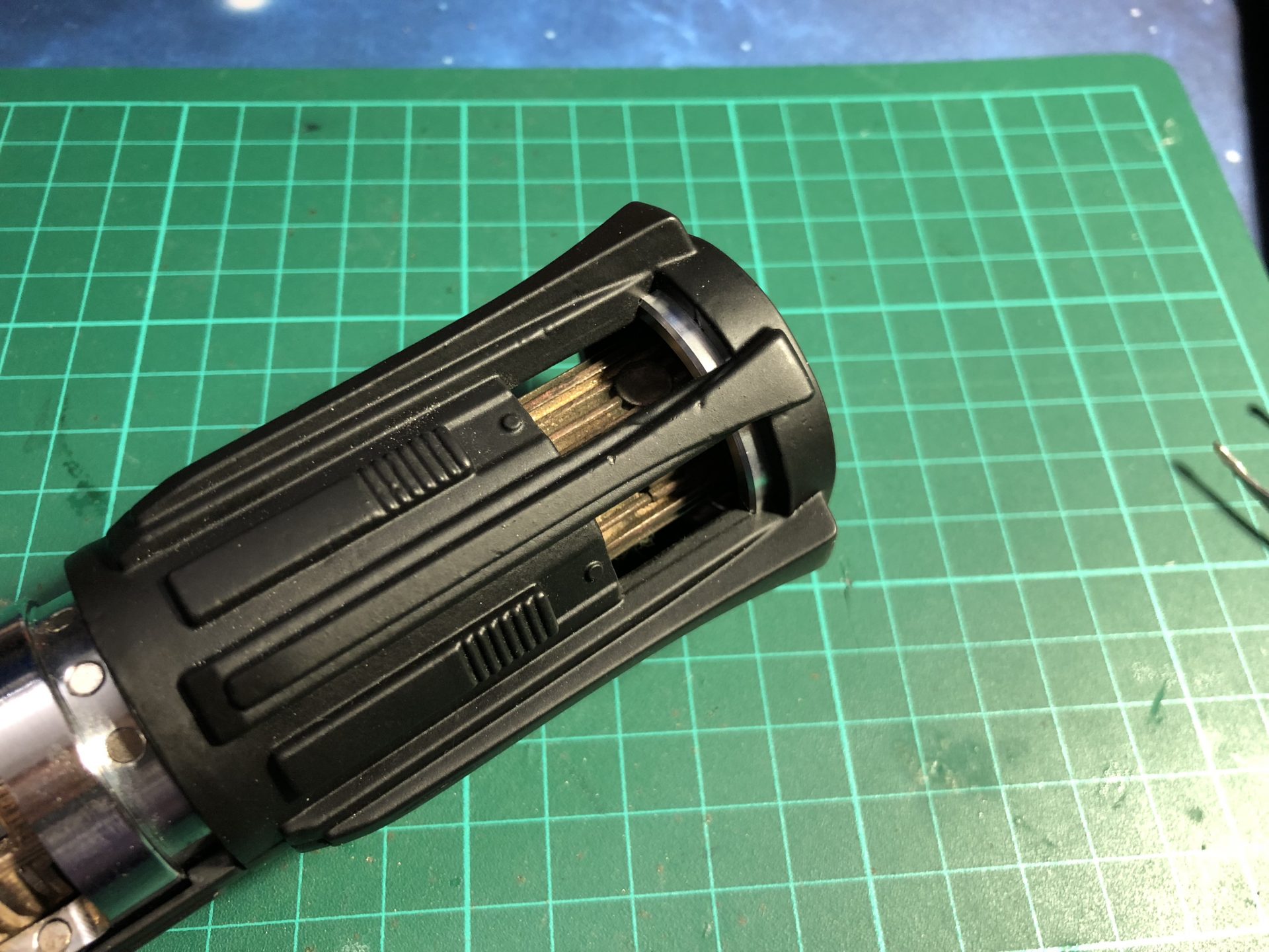
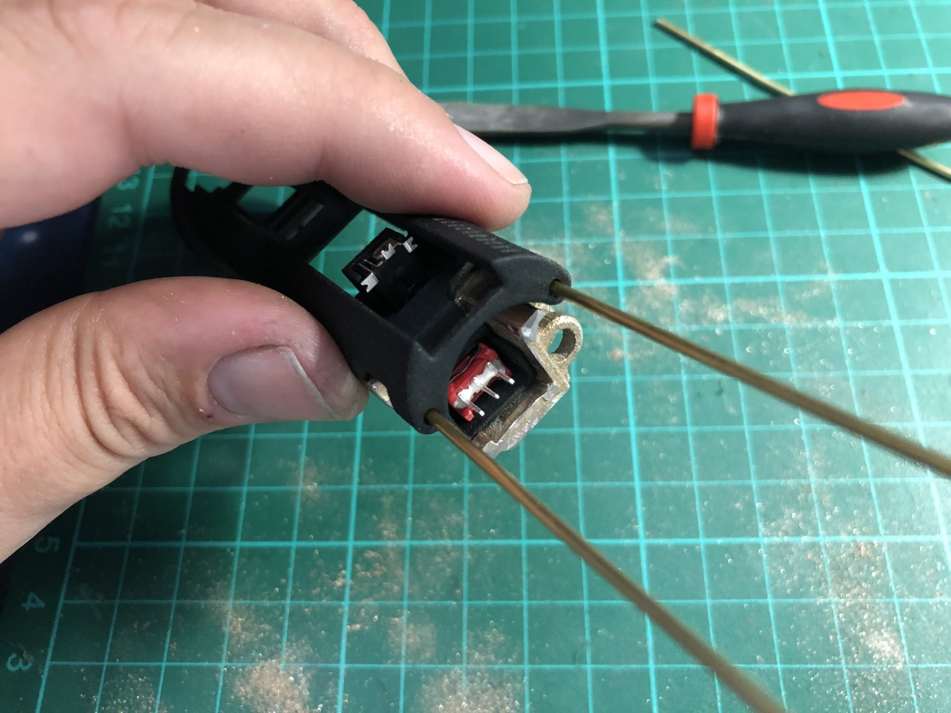
4) All our chassis are compatible with the following Aux switch assembly.
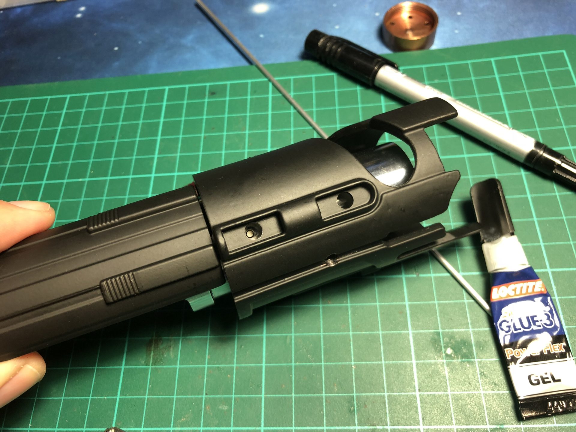
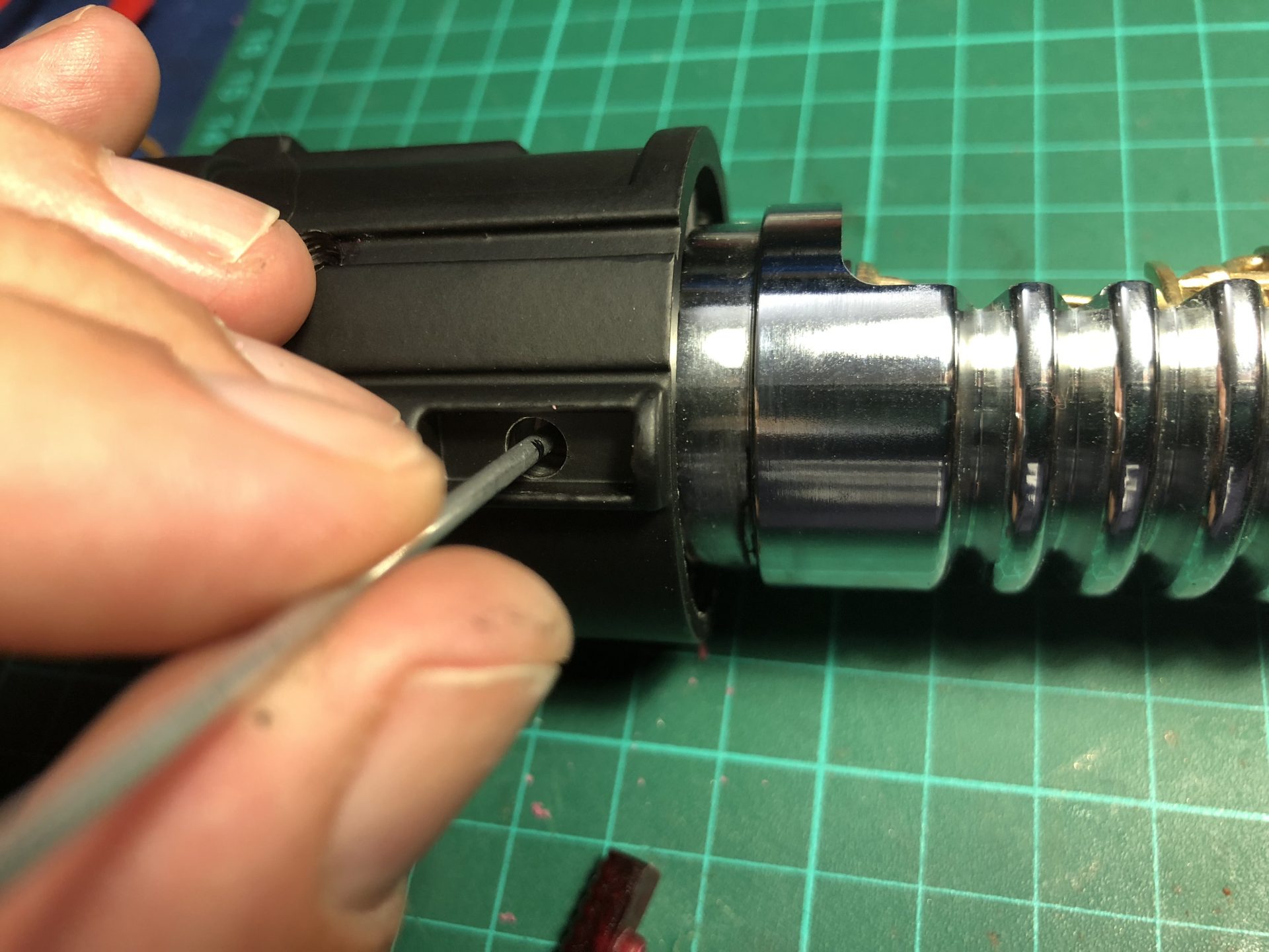
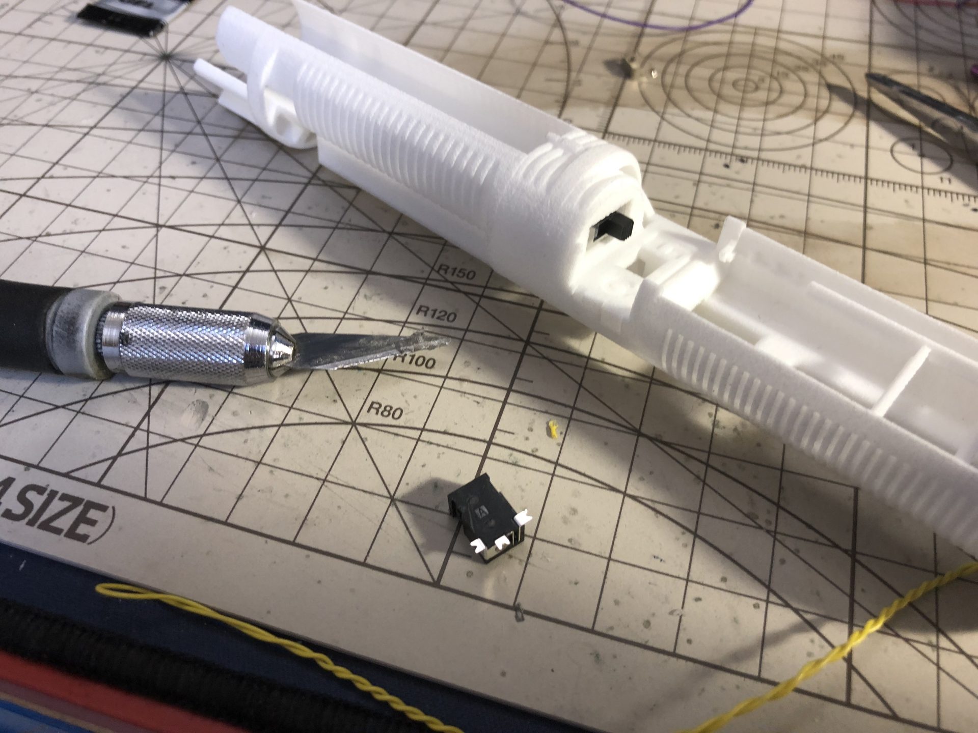
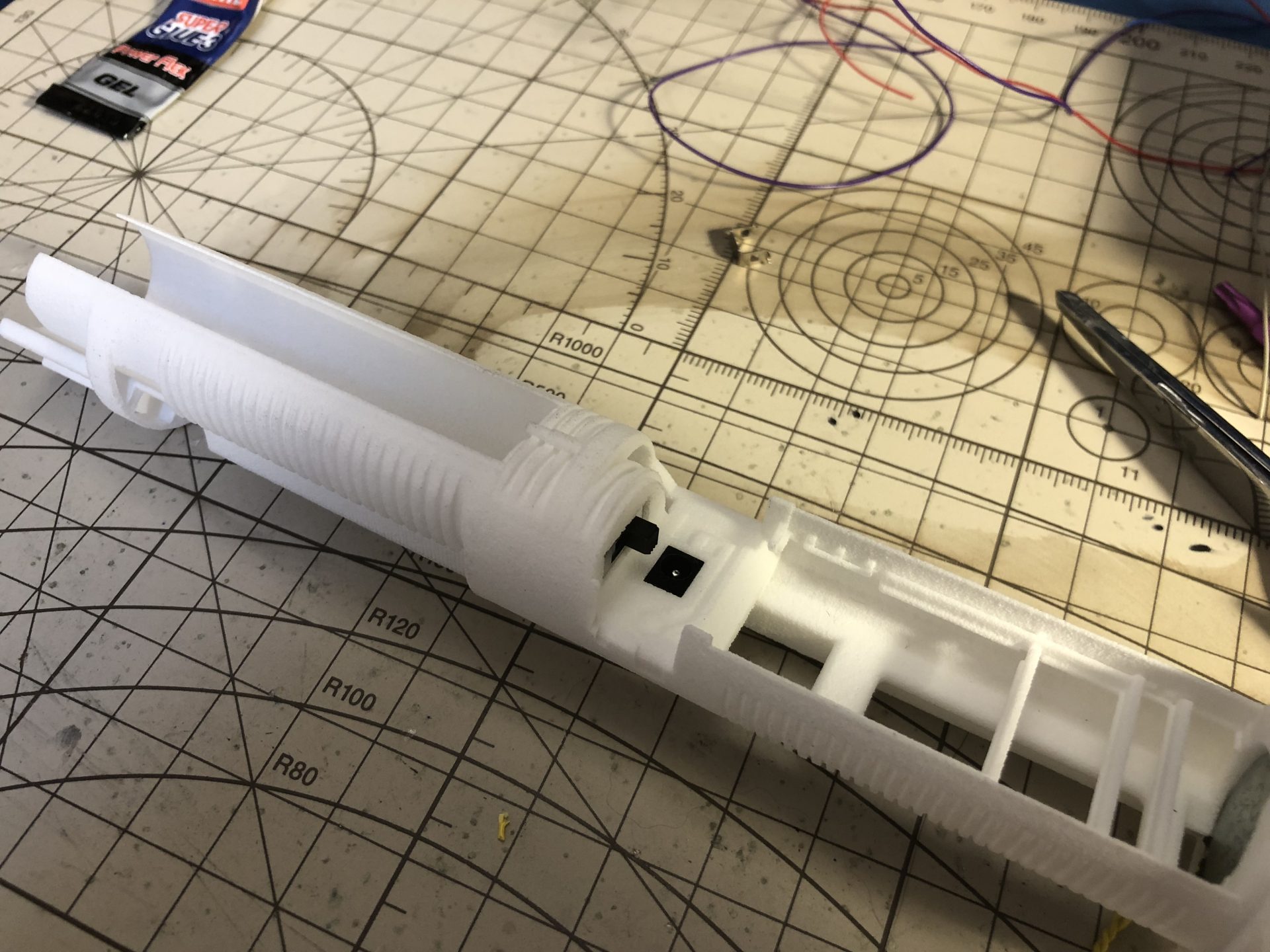
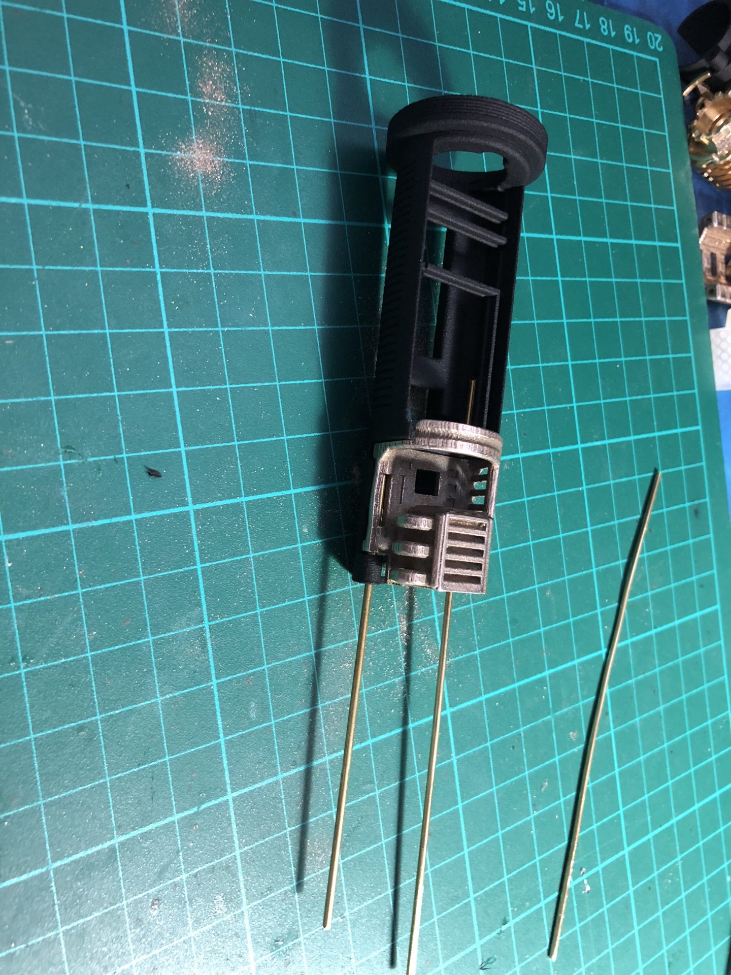
A 2.3mm ID hole will need to be added to the inner tube, located under the bottom red piece slot. Insert the shroud, mark where the hole is located and drill.
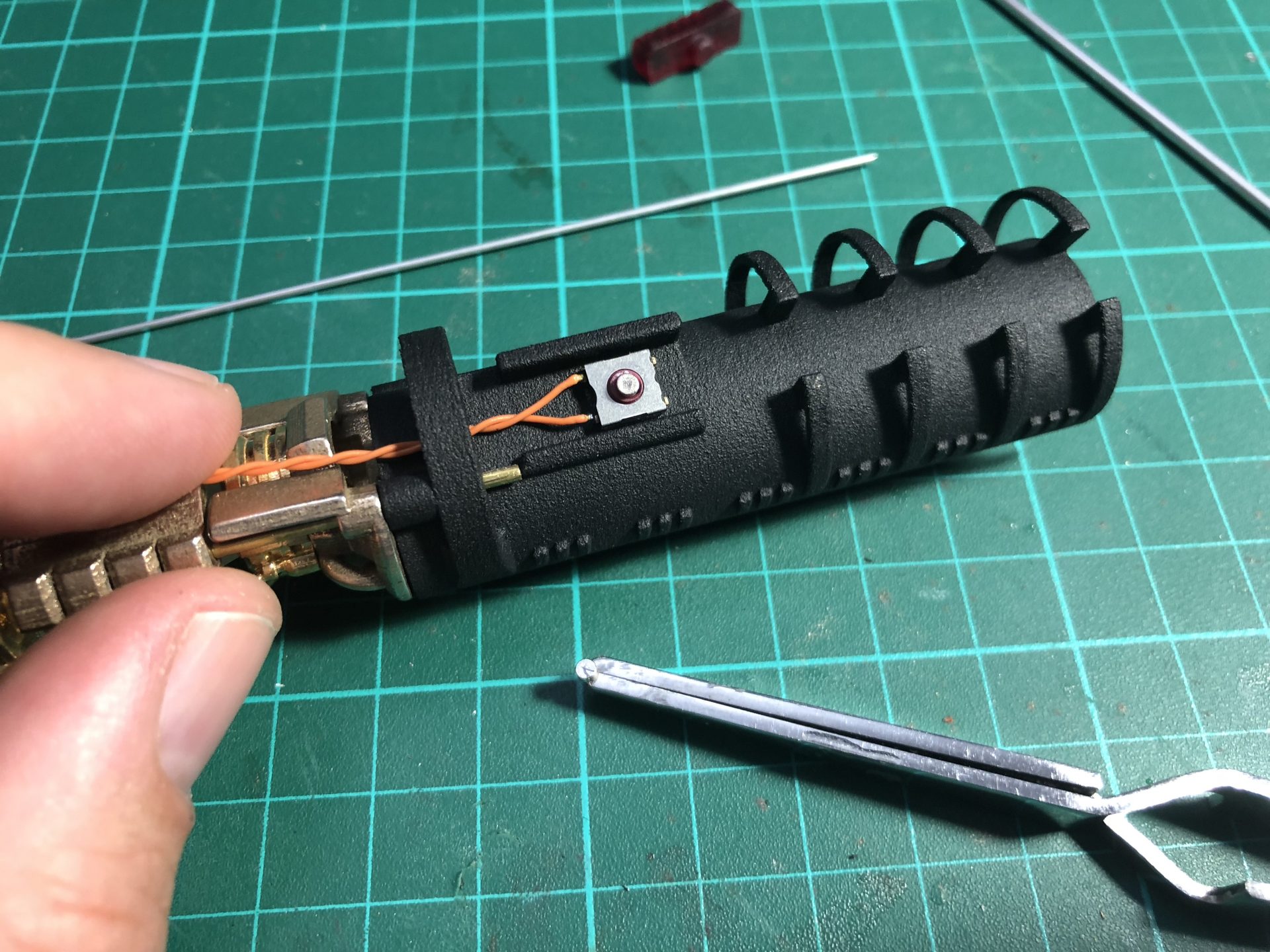
Once the hole drilled, temporarily insert the full chassis in order to mark the exact position where the tactile switch needs to be glued (the red button needs to match the hole).
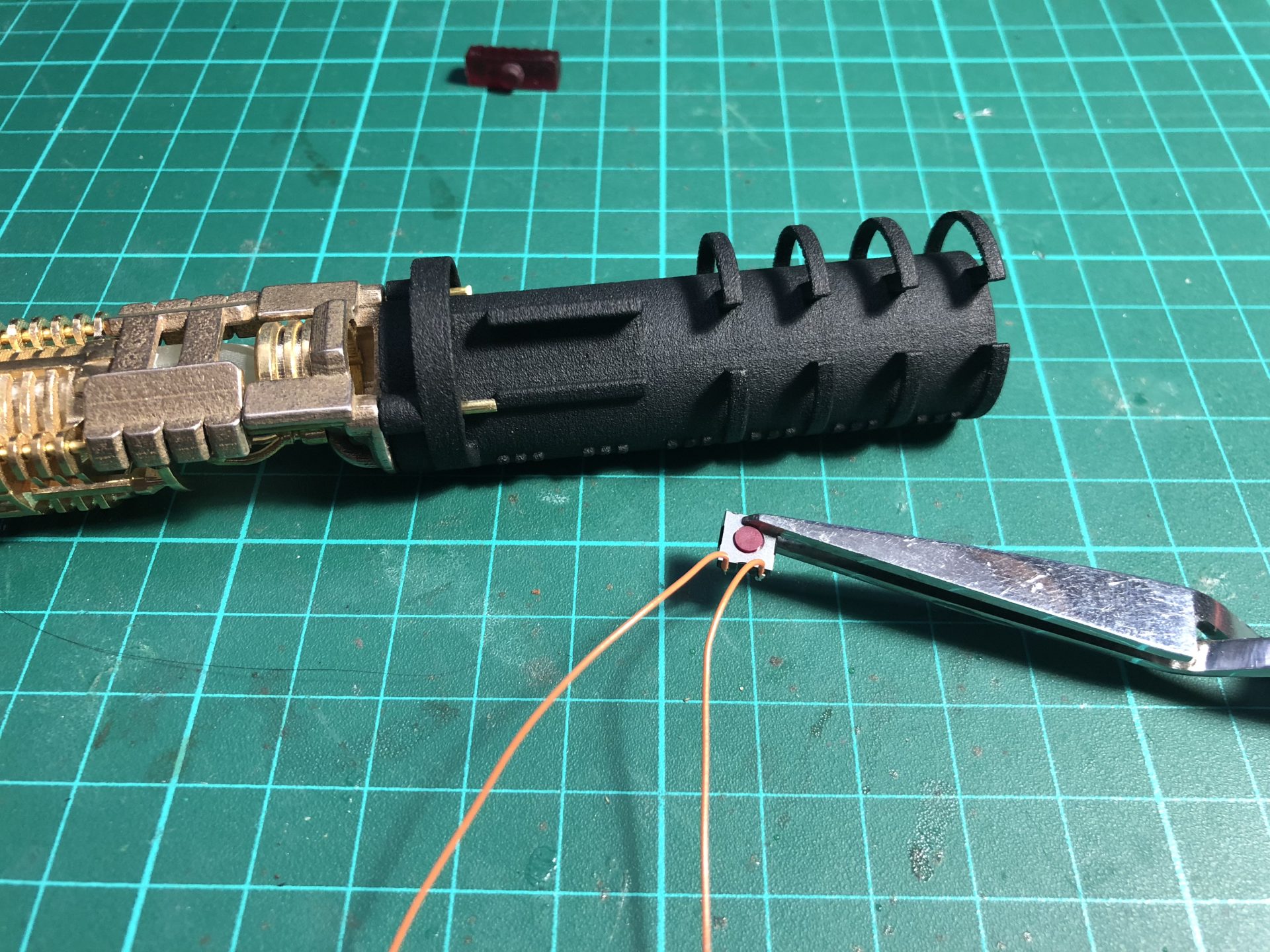
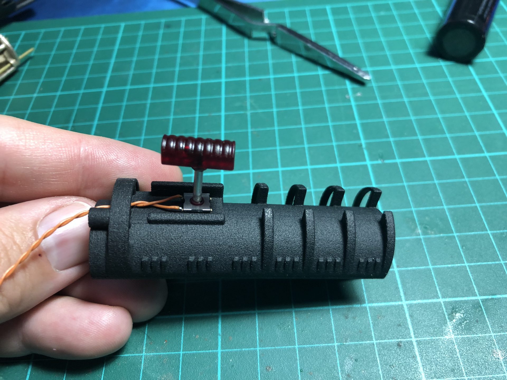
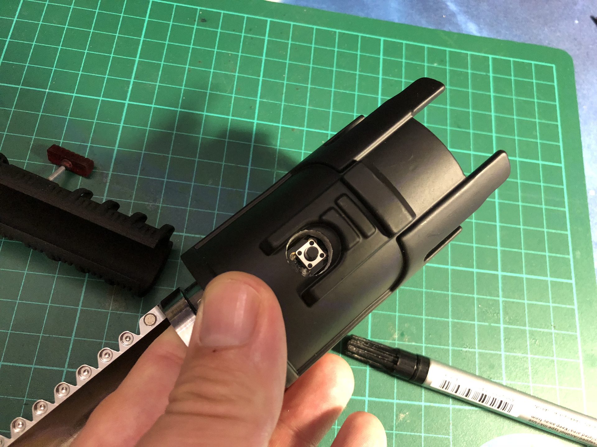
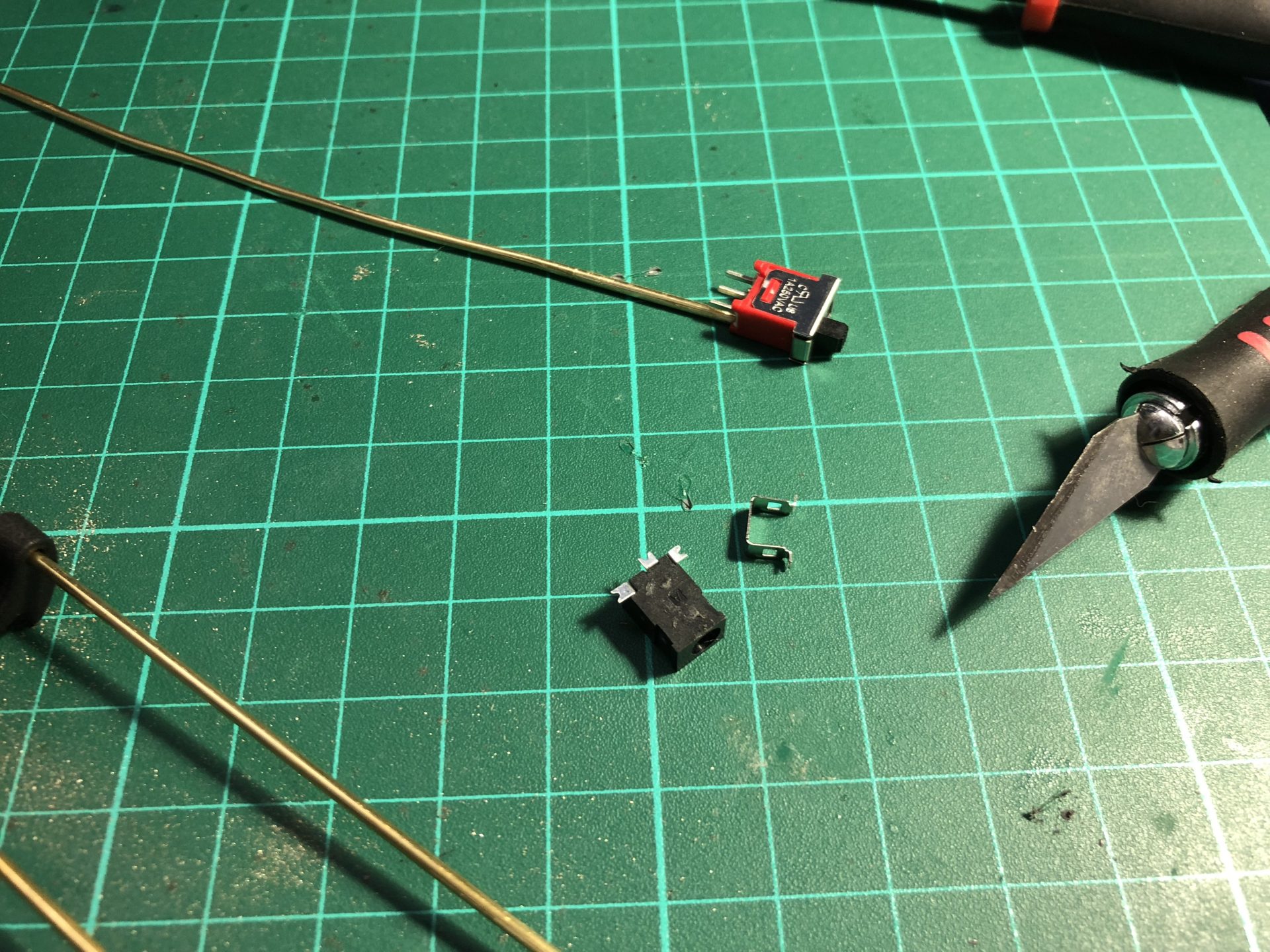
Glue a 1mm tall x 2mmOD magnet on top of the red button of the tactile switch.
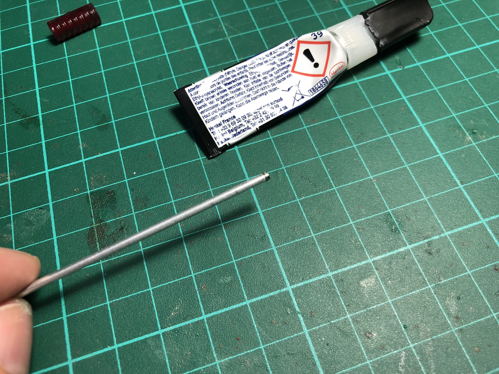
Glue the other magnet on a 2mmOD rod, making sure to respect the polarity with the one on the switch.
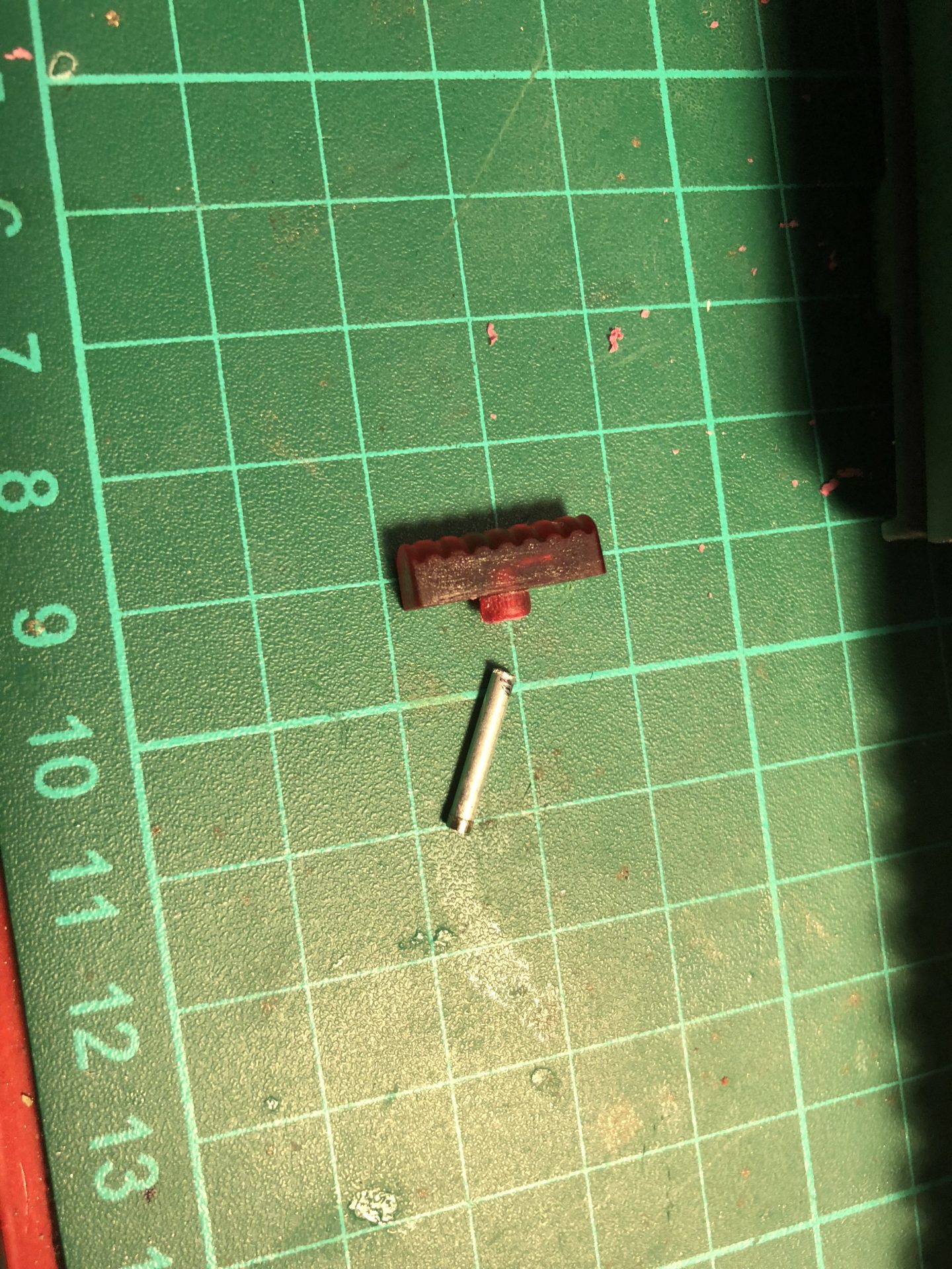
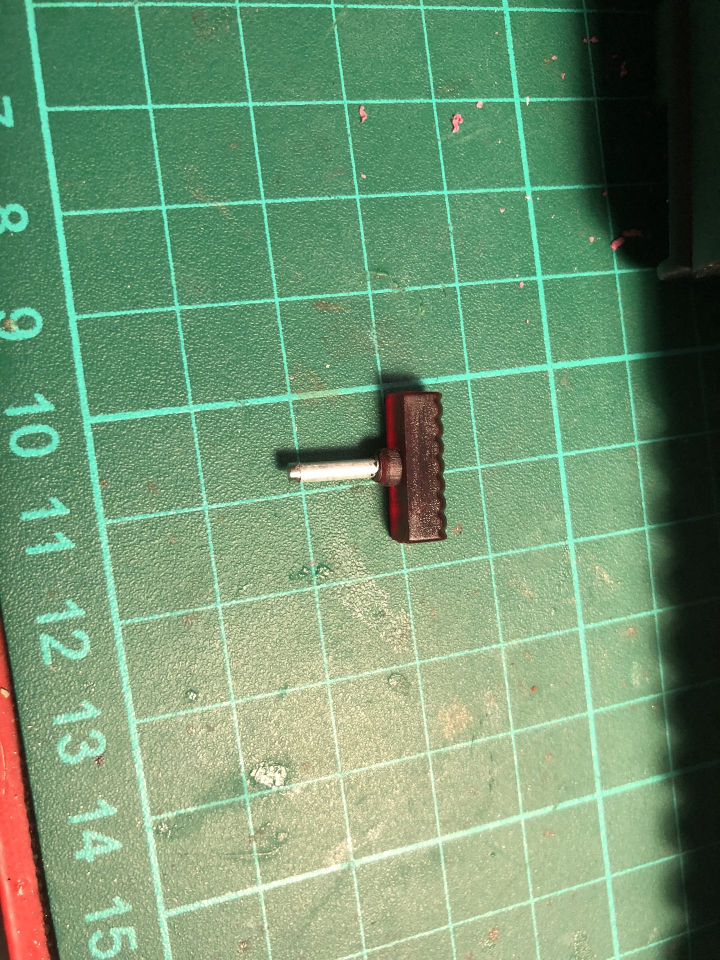
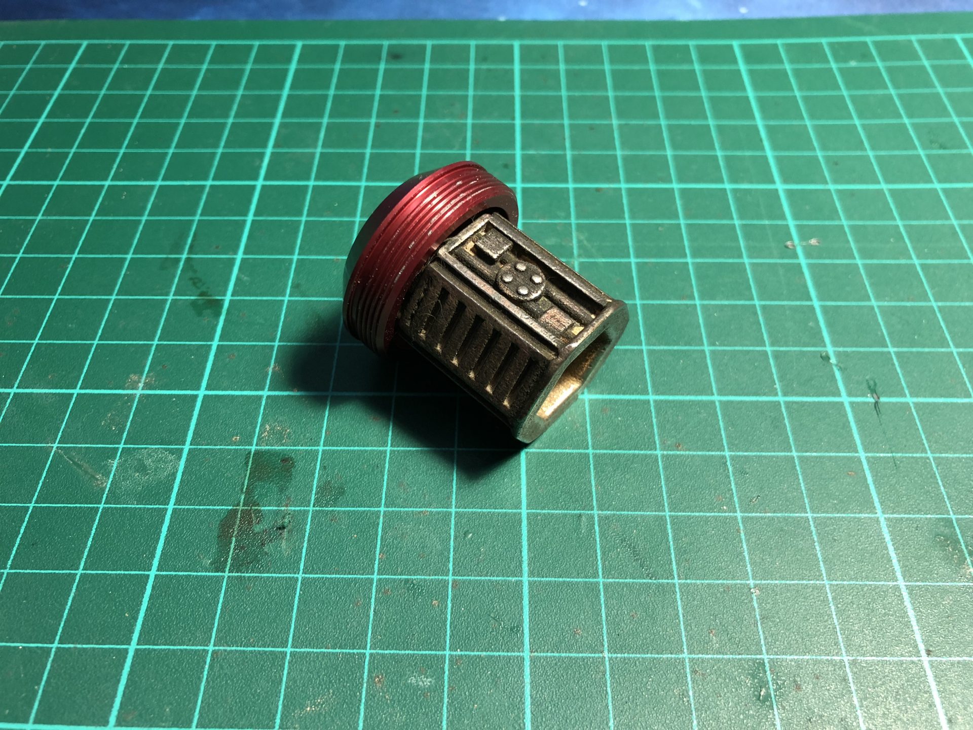
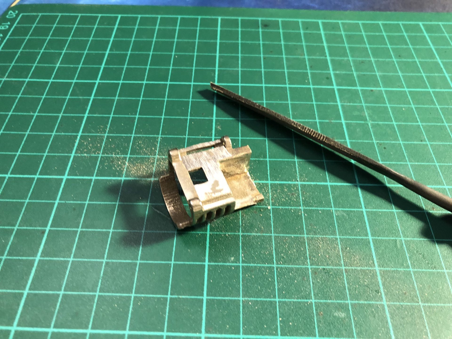
Drill the red piece as shown below (approx 3mm deep) and cut the rod accordingly.
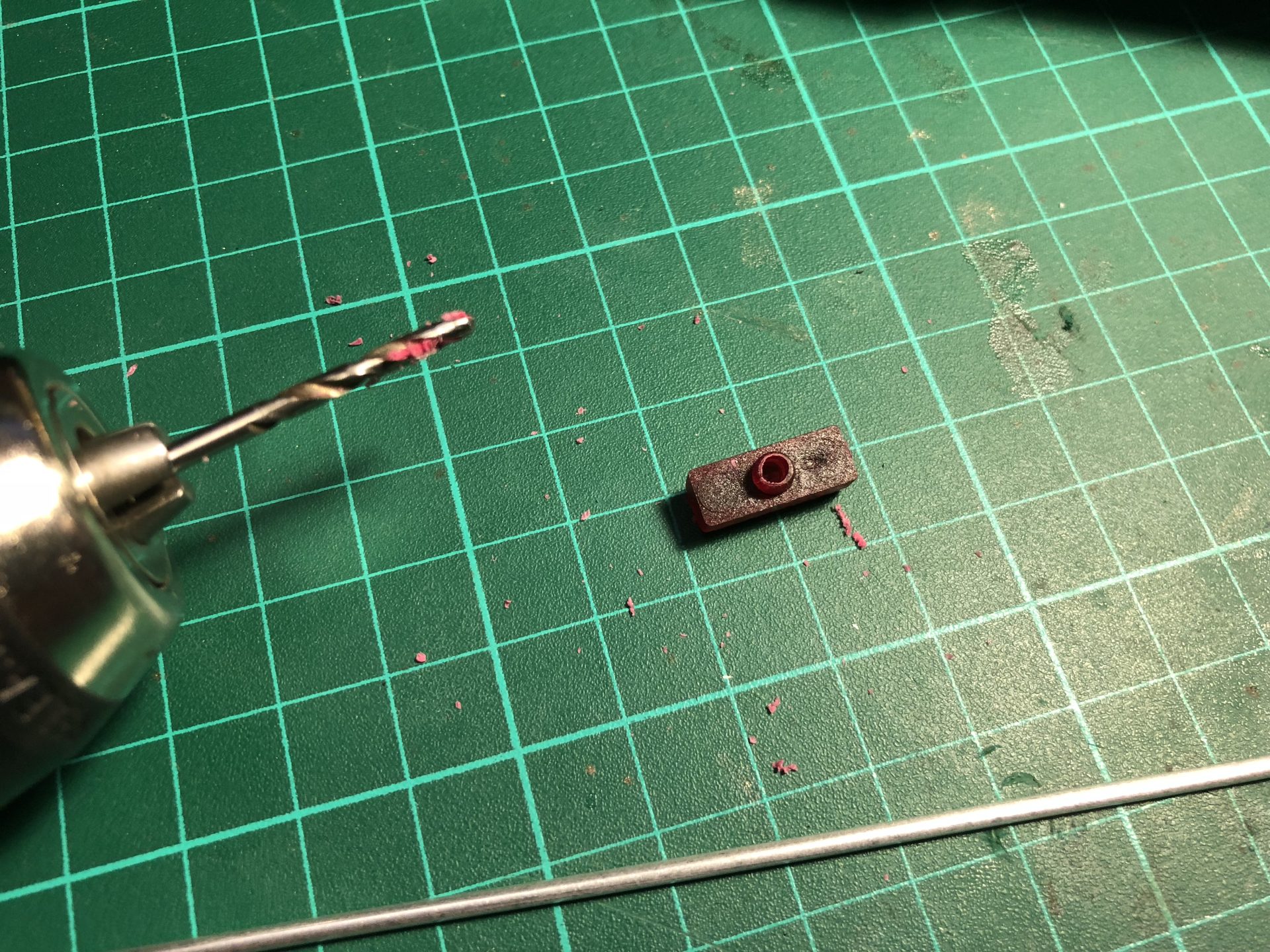
Assemble the rod with the red piece, then test.
5) The side screws holding the red wire holders and cover plate are not to be used with our chassis. They are just complicating things while not bringing much value added to the build. We recommend instead to first glue the cover plate (epoxy or else) and then glue the red wire holders, as they are not meant to be removed from the hilt anyway.
6) It is recommended to use the replacement pommel insert for better sound venting. Good results are obtained when printed in Steel, then sanded and weathered.
Padawan
Install the main leds or neopixel connector first, with enough wires length to exist from the pommel and be able to solder them to the soundboard.
The Padawan chassis are pretty straightforward to install, here are a few particularities to take into account:
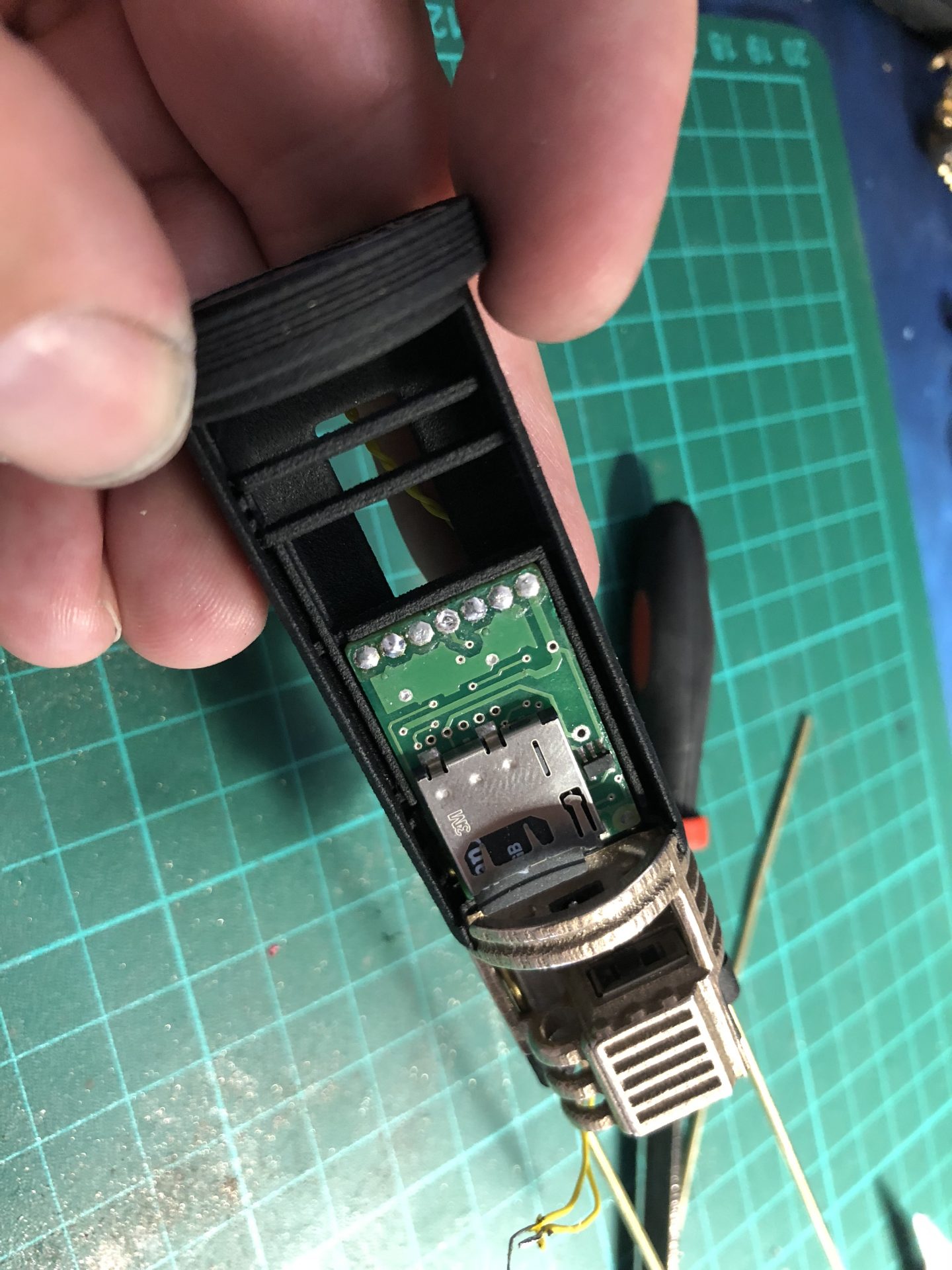
– Padawan Var1 – The Keystone holder will need sanding on one side in order to allow SD card access (~3mm need to be removed). Sanding the Negative side battery side is recommended if you have a polarized Keystone holder.
– Padawan Var2 – On/Off switch and Recharge port are installed as follow, and accessible by removing the side cover plate.
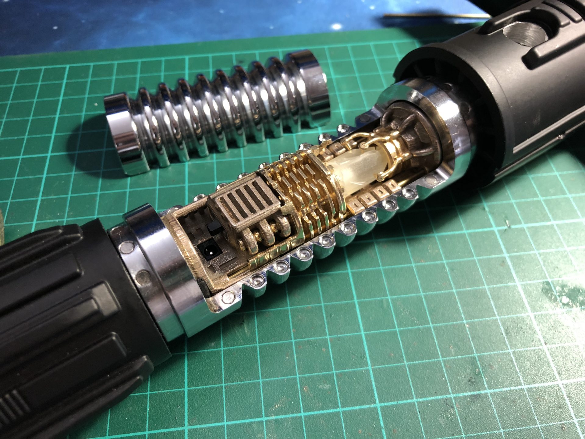
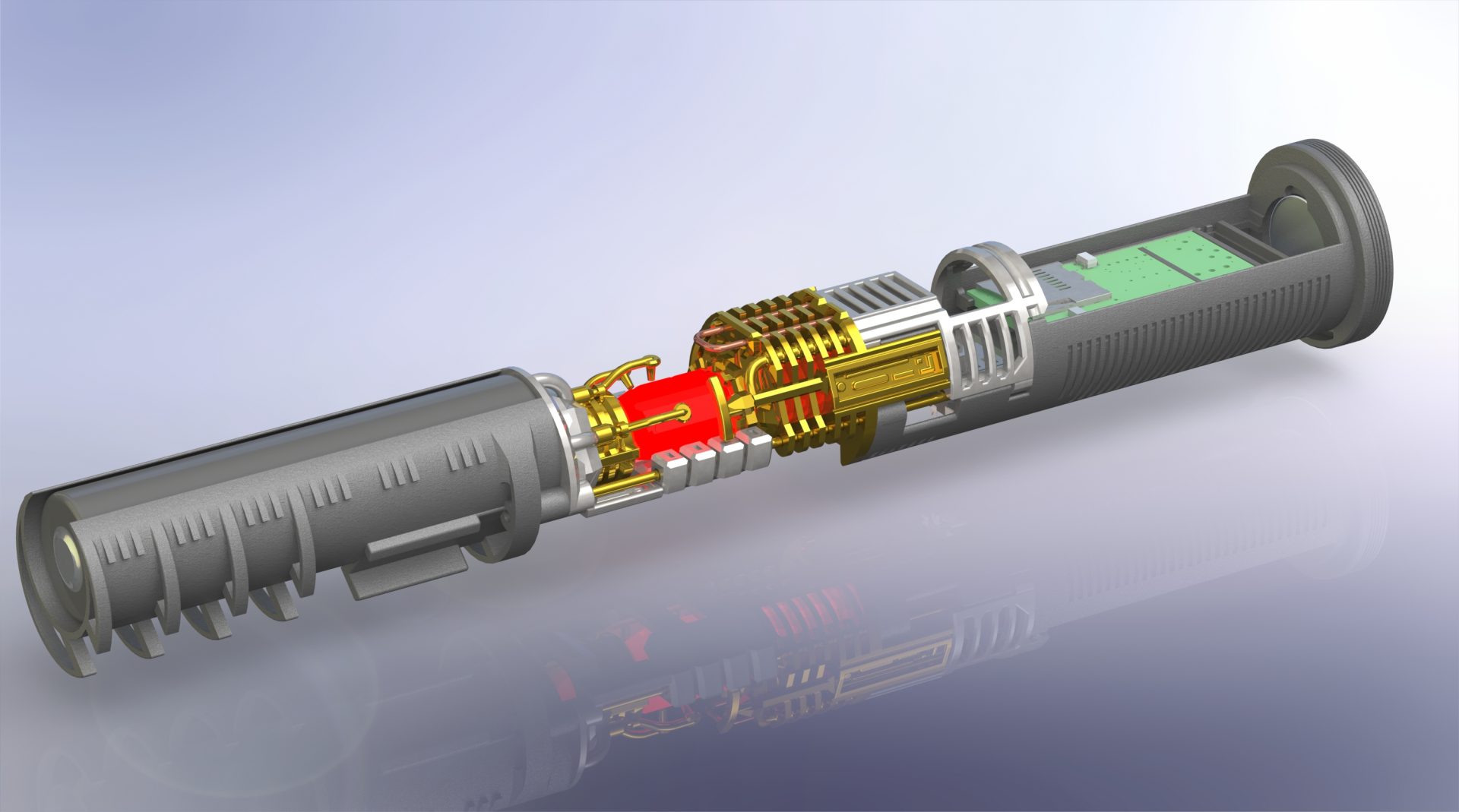
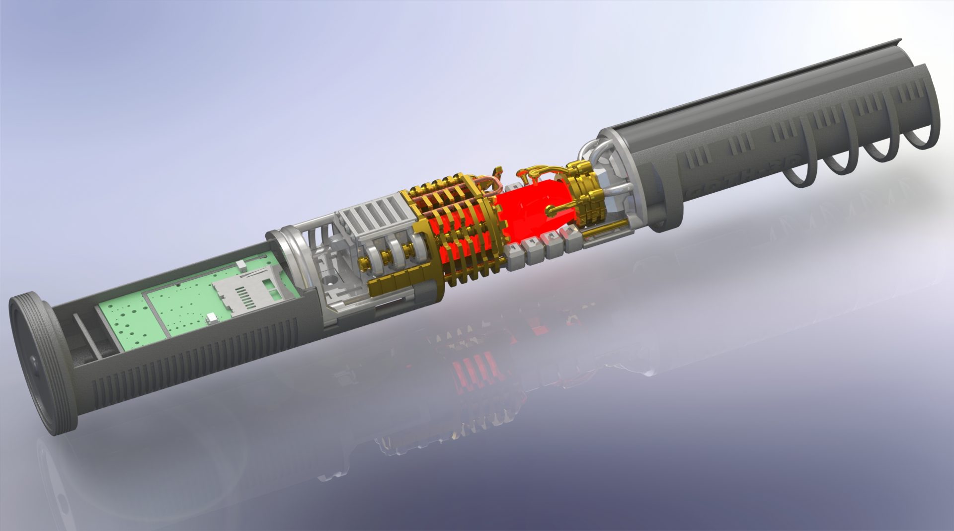
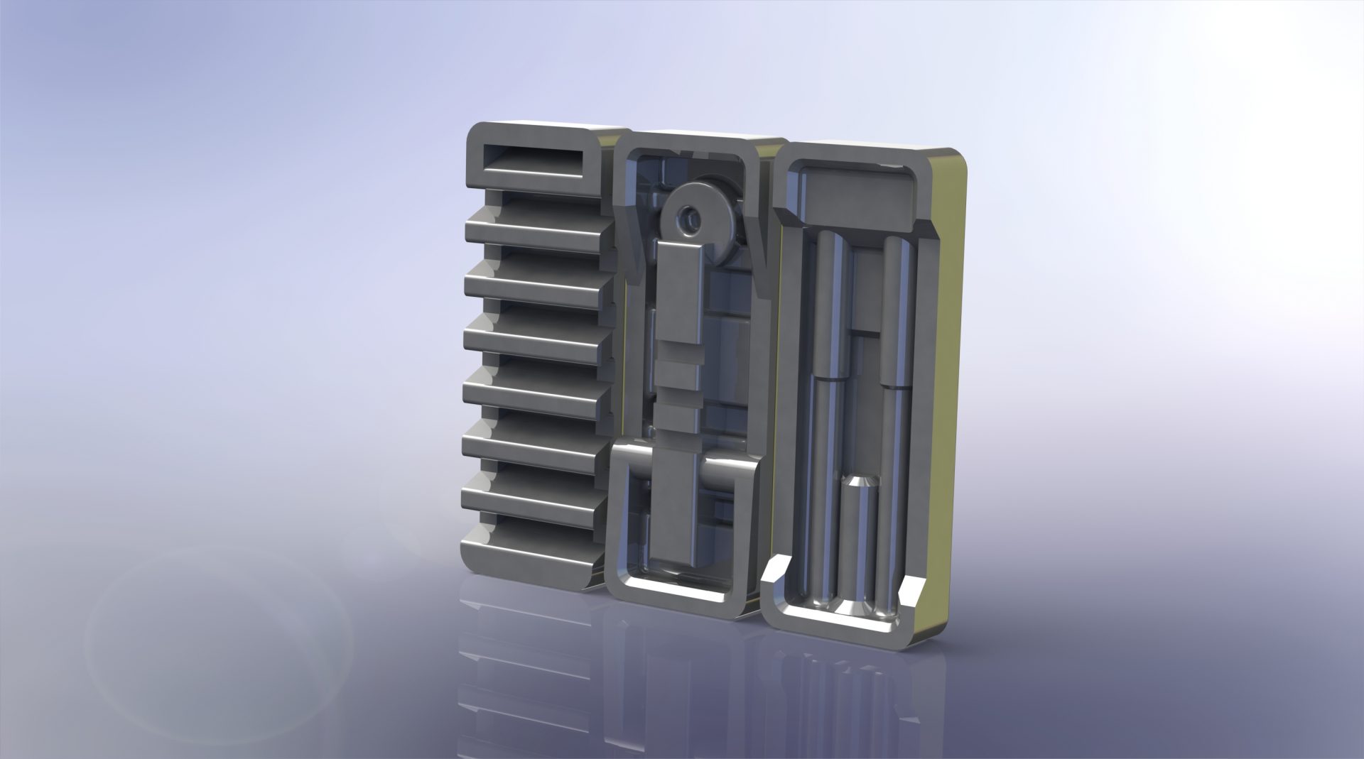
Master
Install the main leds or neopixel connector, and main switch first, with enough wires length to exist from the pommel and be able to solder them to the soundboard.
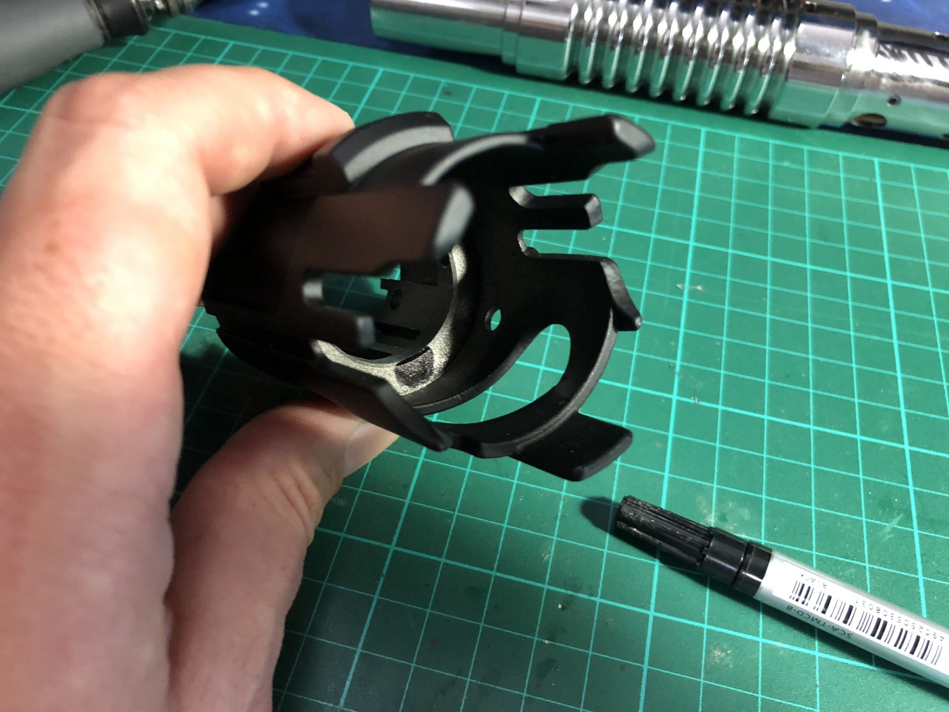
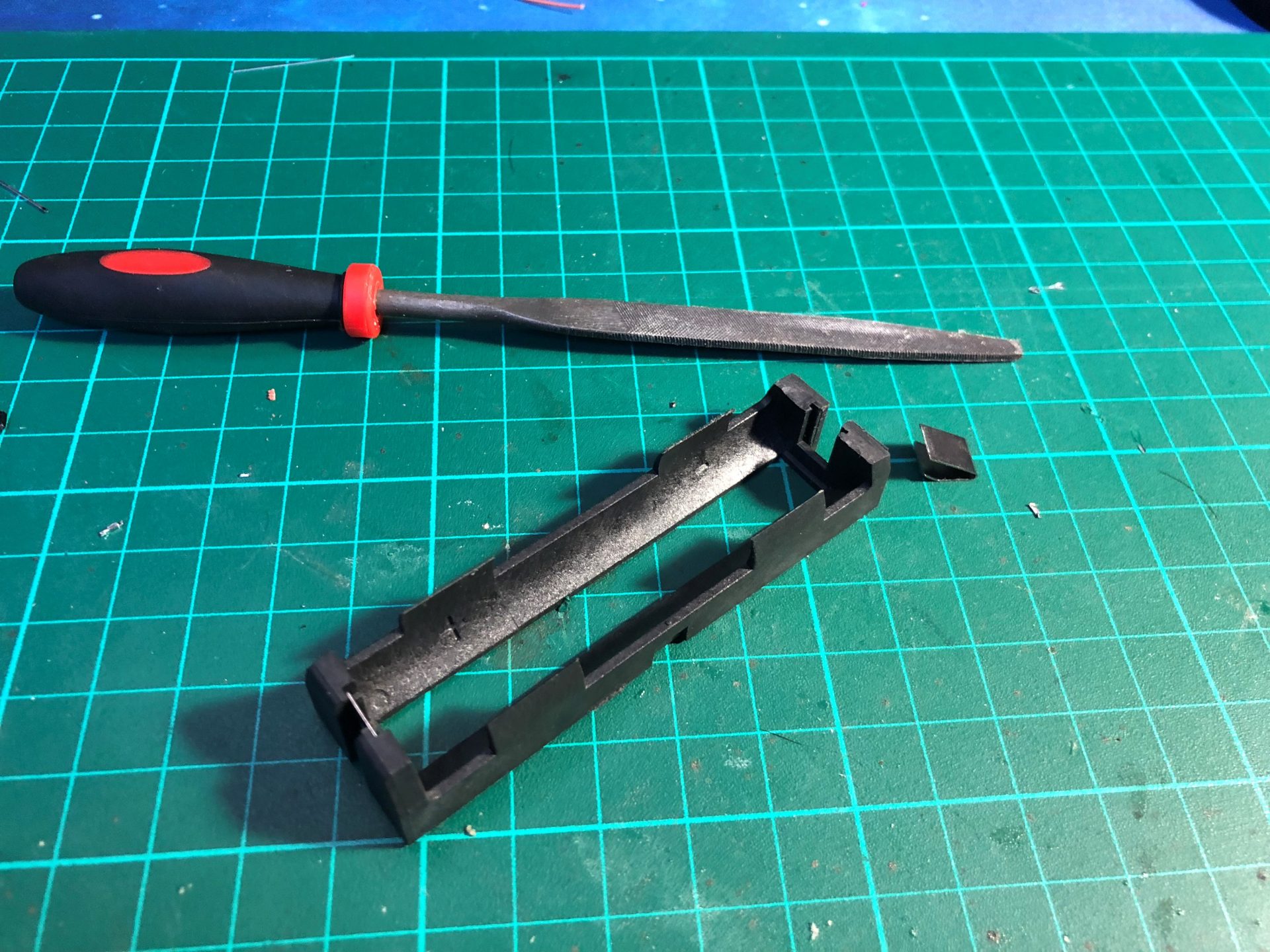
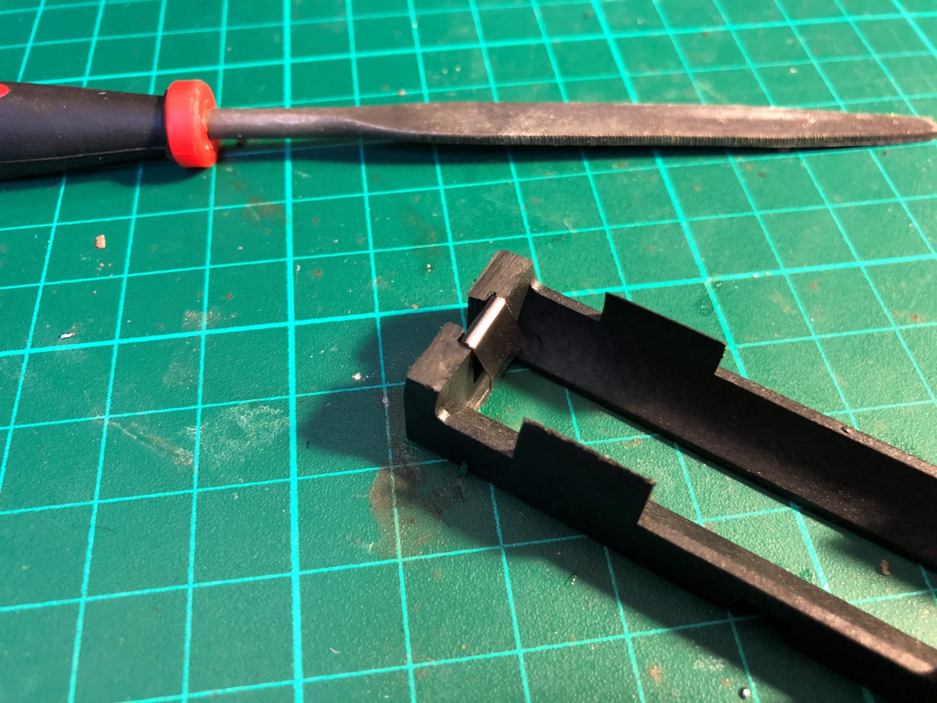
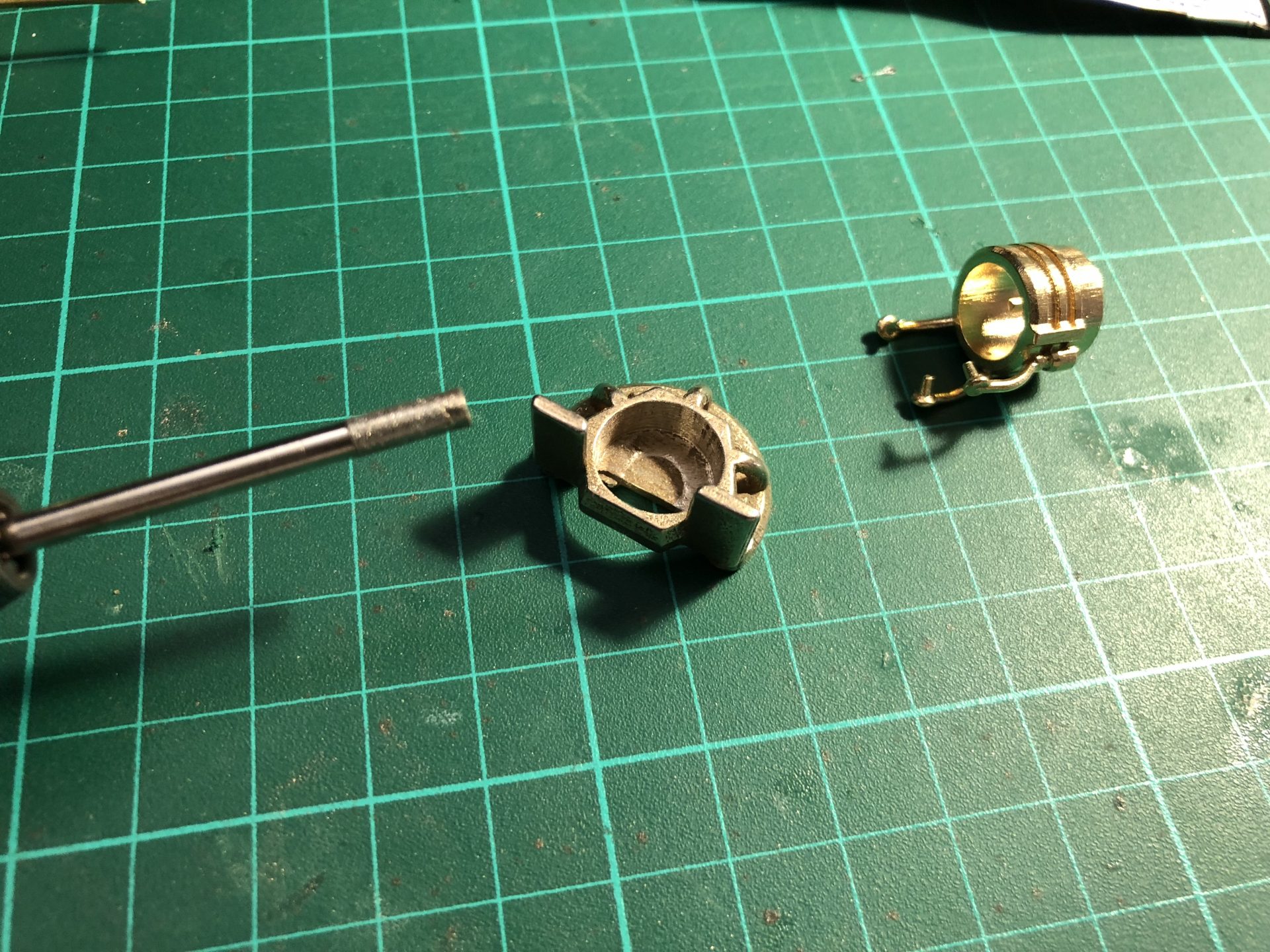
Part3 – CC insert 2 contains 2 parts that needs to be separated
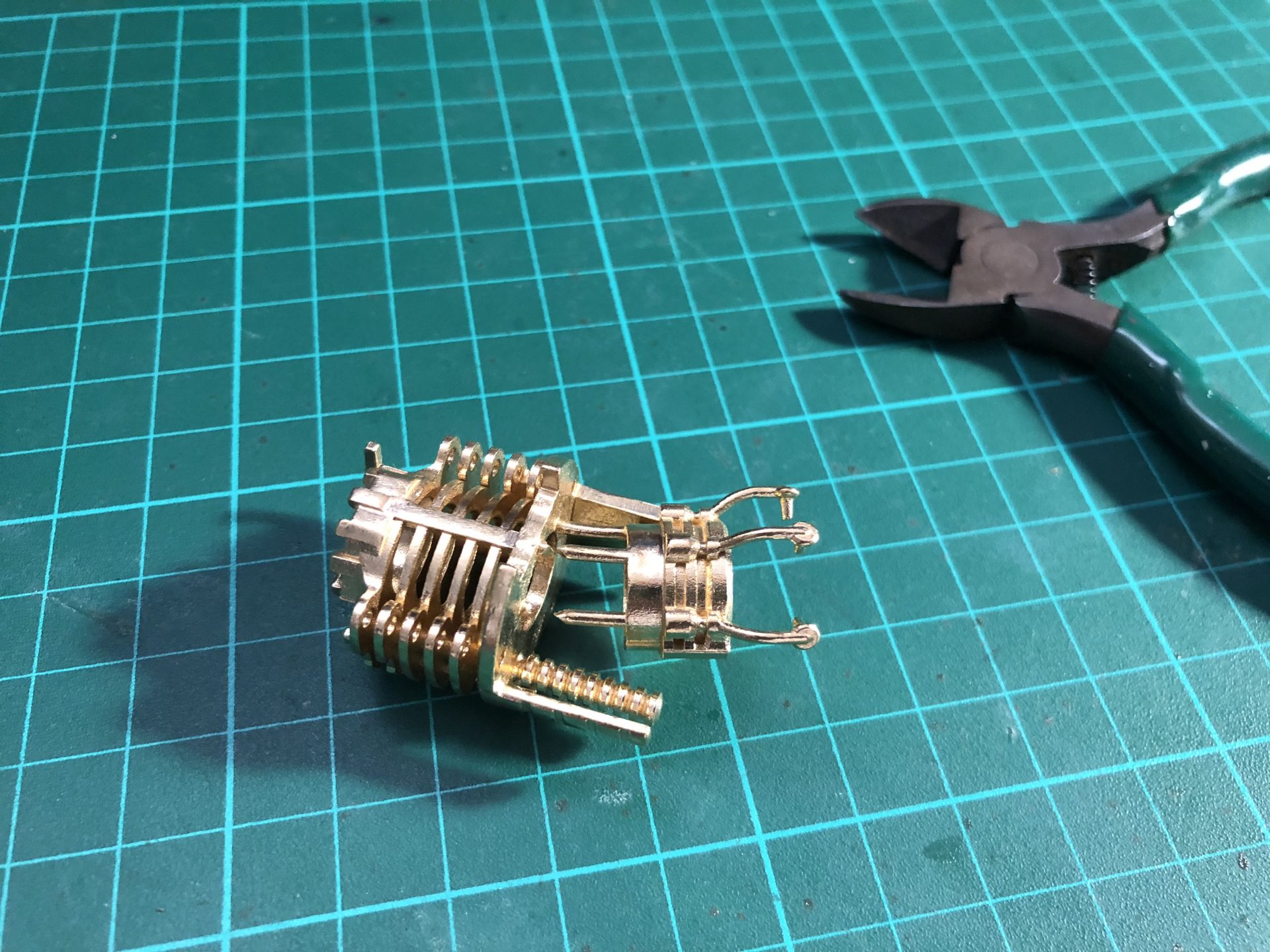
When part are printed in steel, some sanding would be required to make parts fit properly. First insert the two 1.5mmOD rods and then add Part2 – CC insert 1.
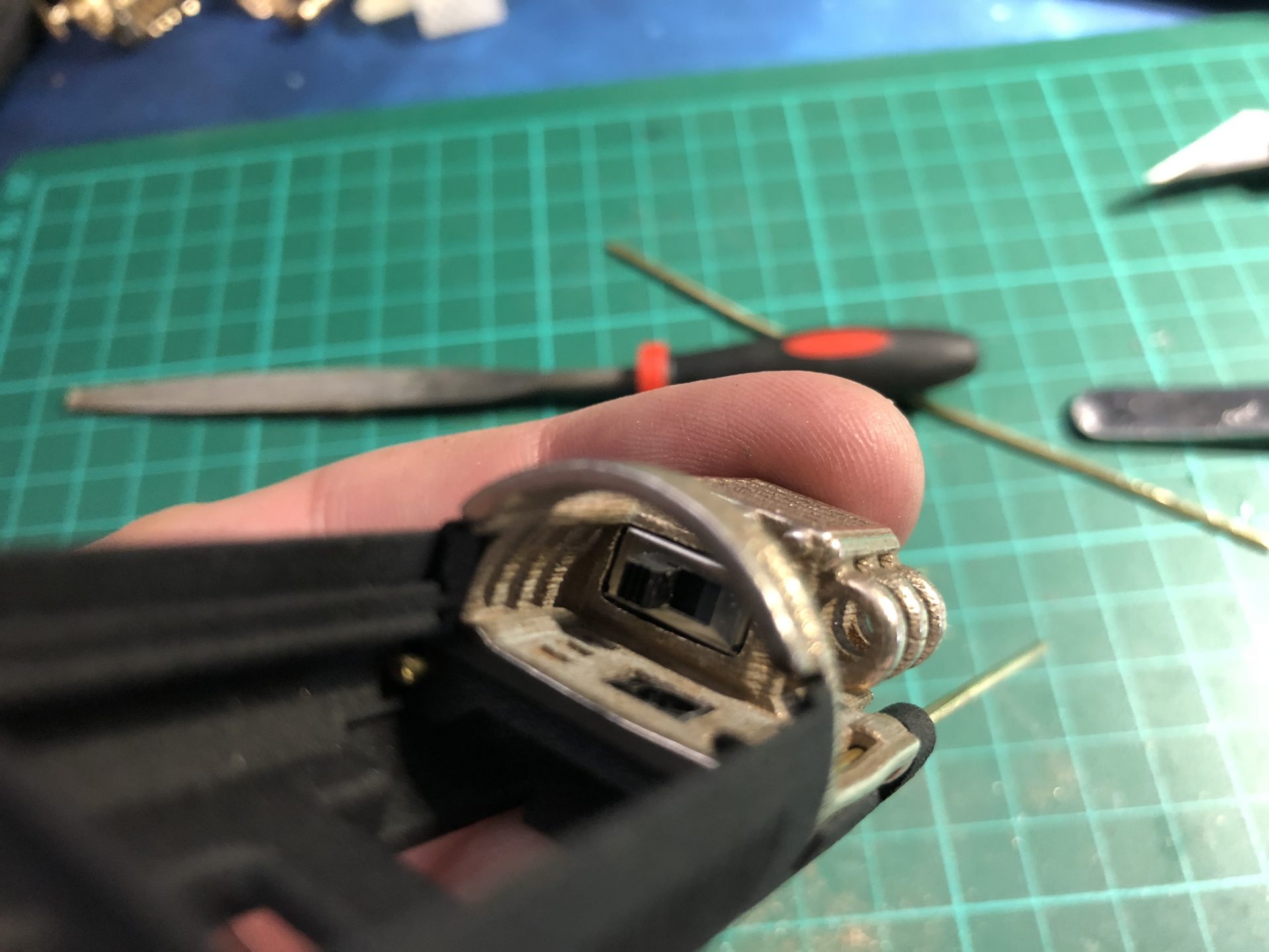
Install the 1.3mm Recharge Port and kill switch in their dedicated slots.
Glue the speaker and install the soundboard with proper wiring planning.
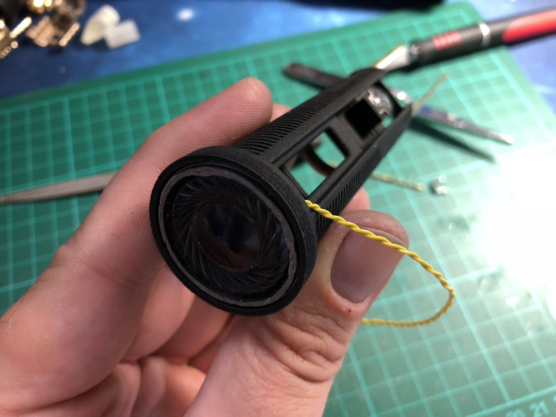
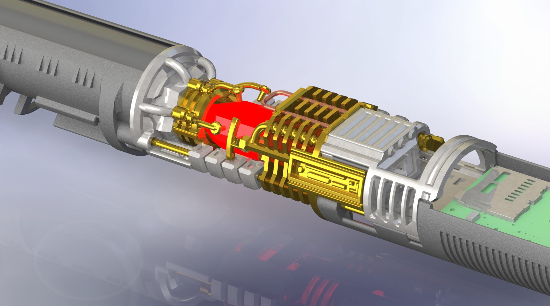
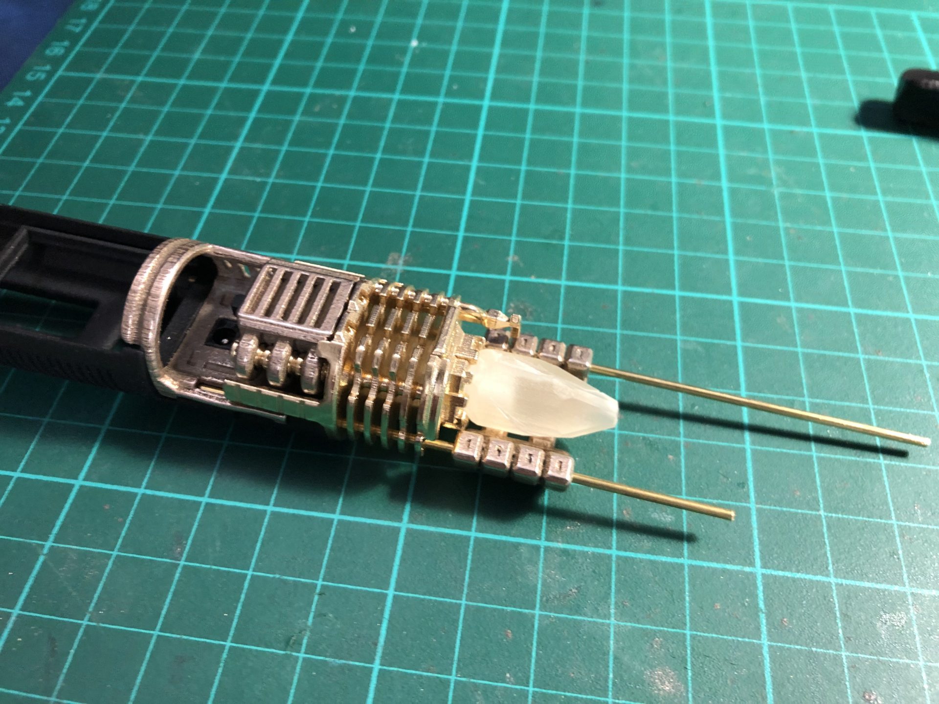
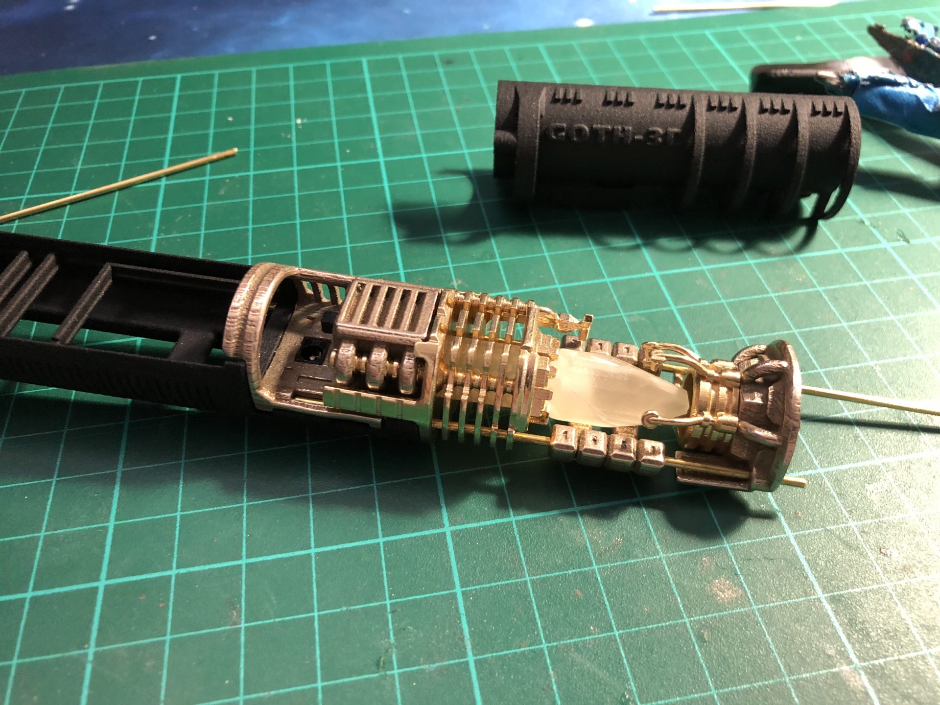
Add the CC Insert 2 to the assembly, and install (glue) the light tube with accent led into it.
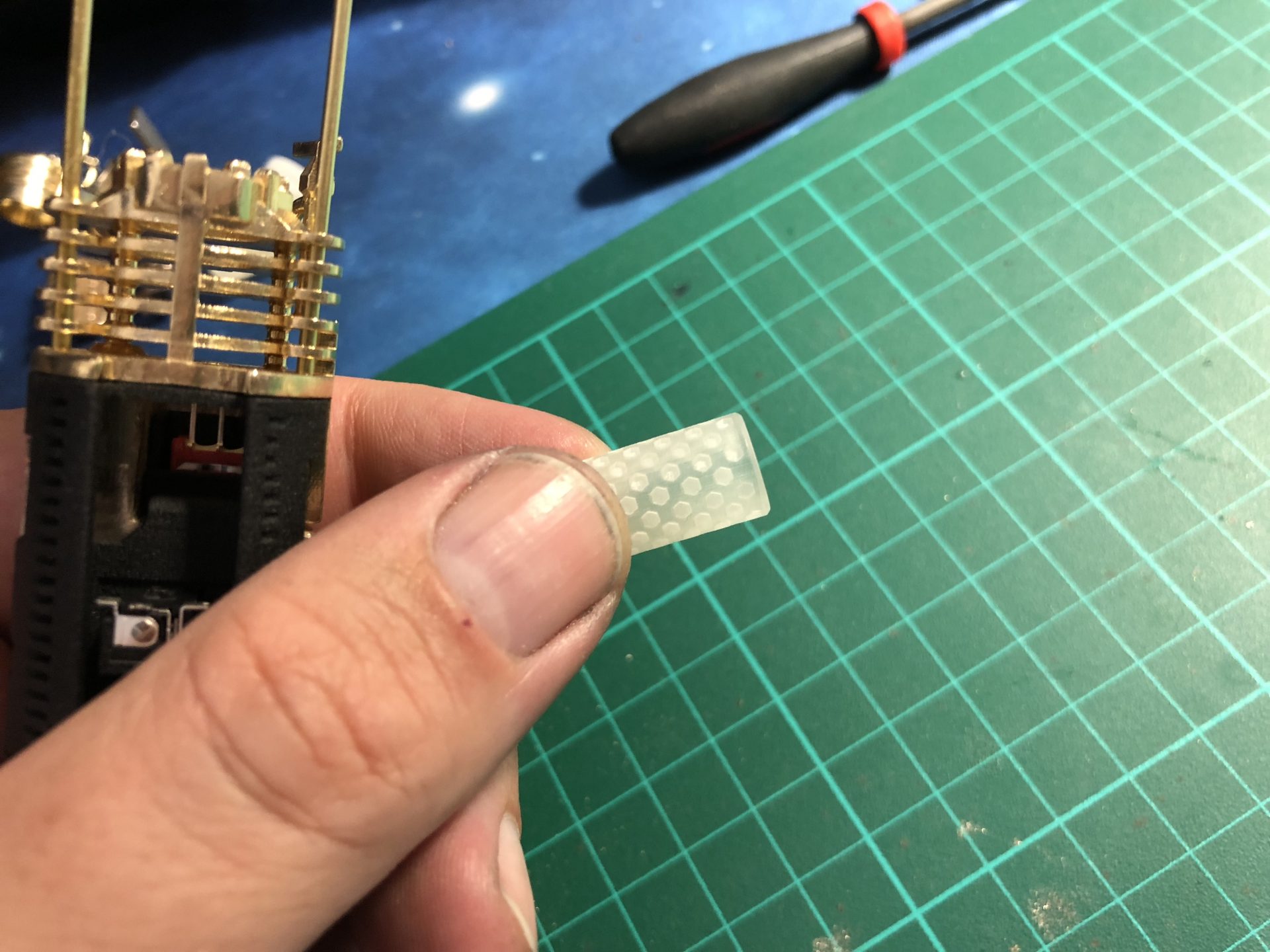
Then add the crystal with accent led.
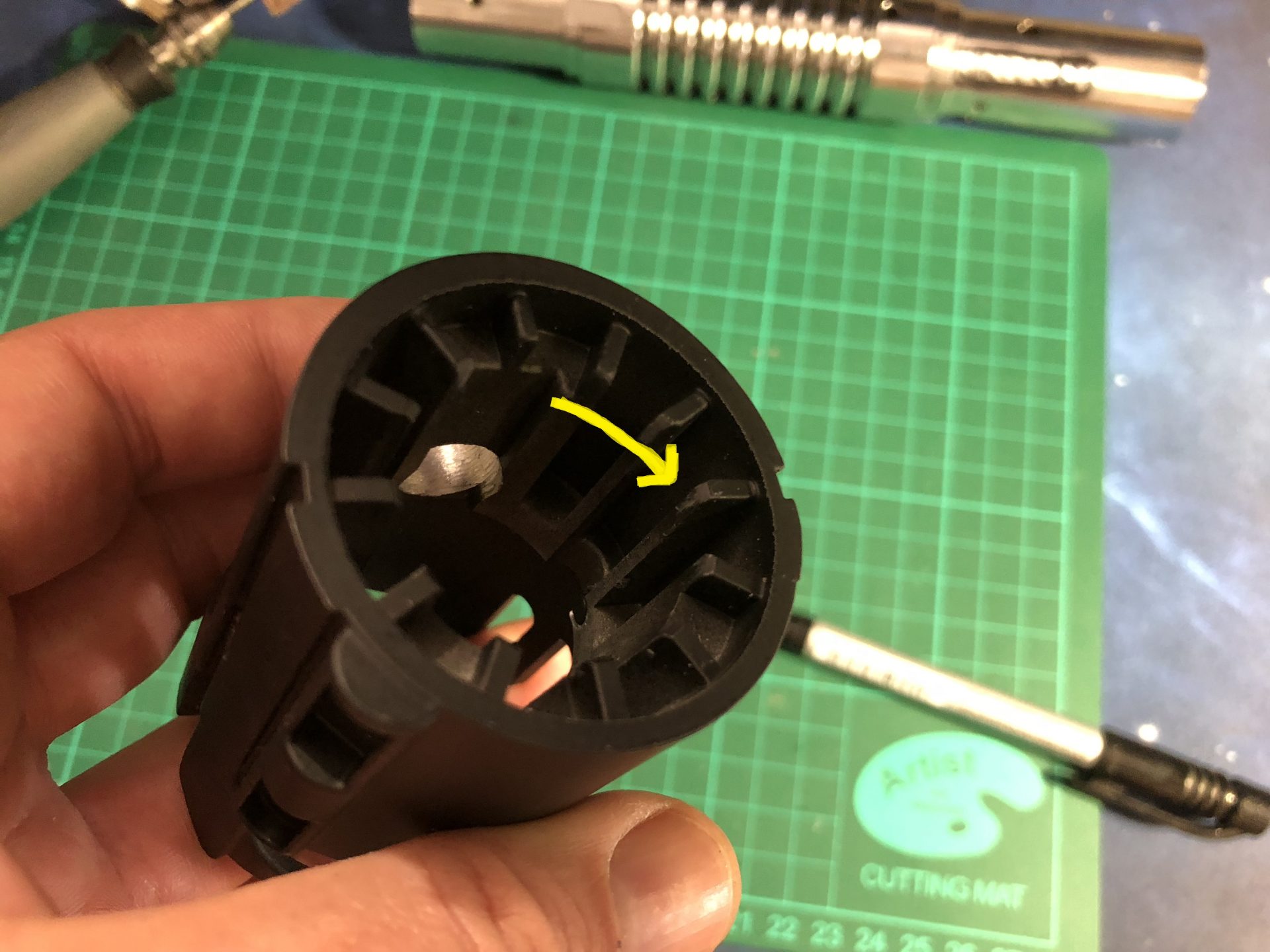
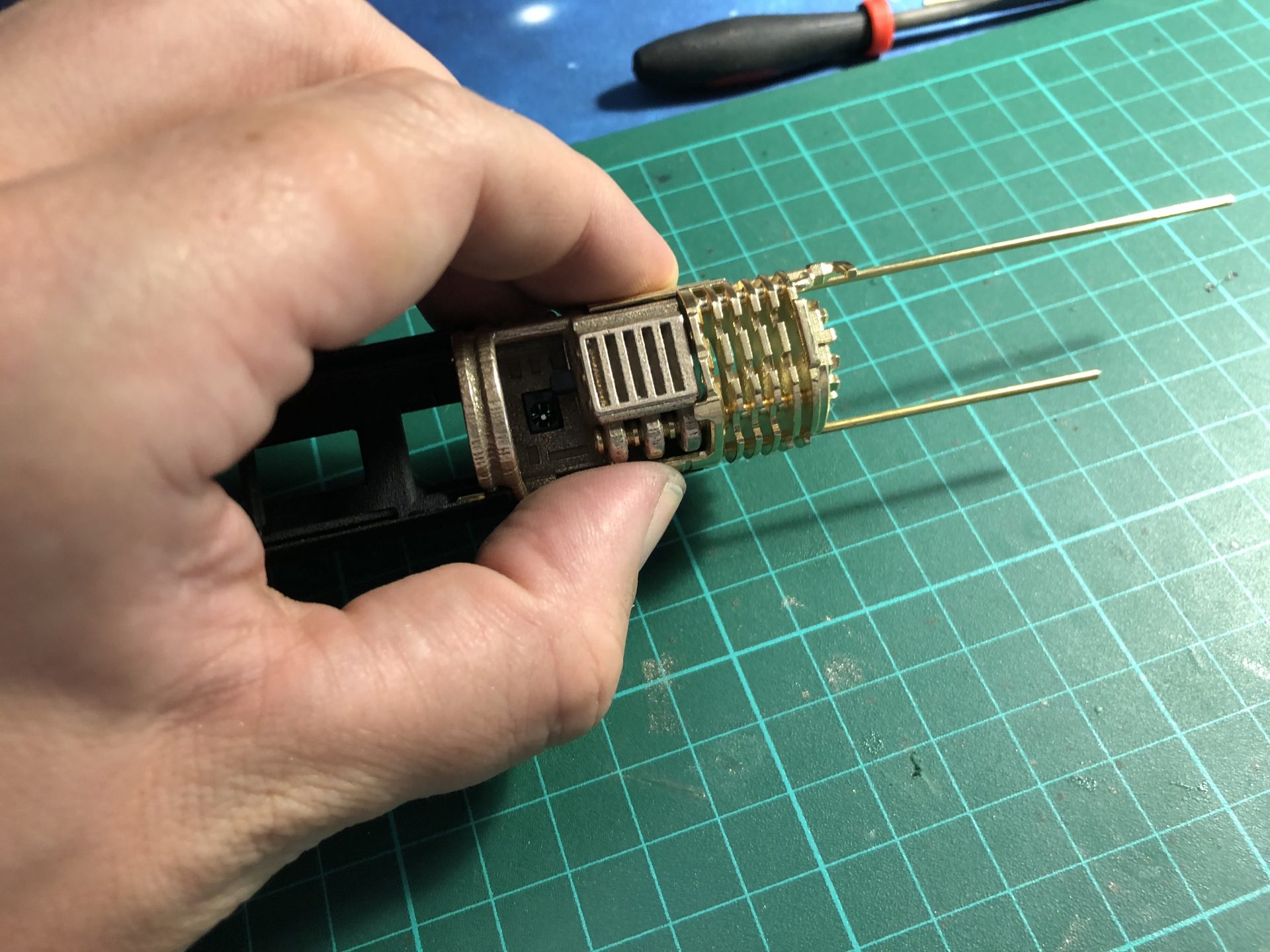
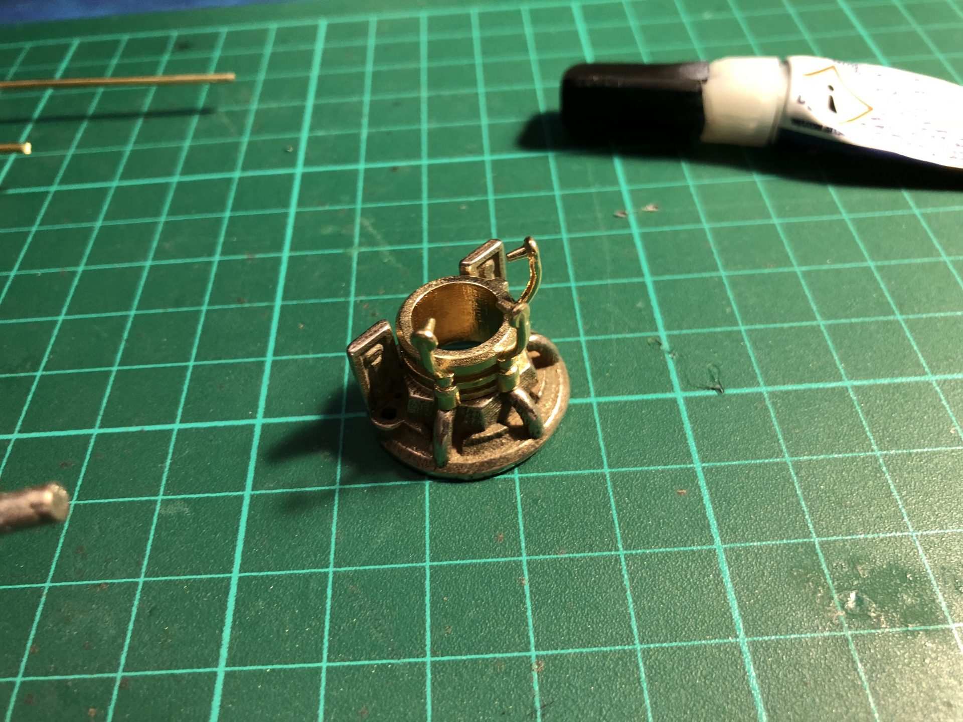
Again, with steel, sanding the hole ID can be required in order to press fit or glue Part6 with the 2nd CC Insert 3 part, as shown below
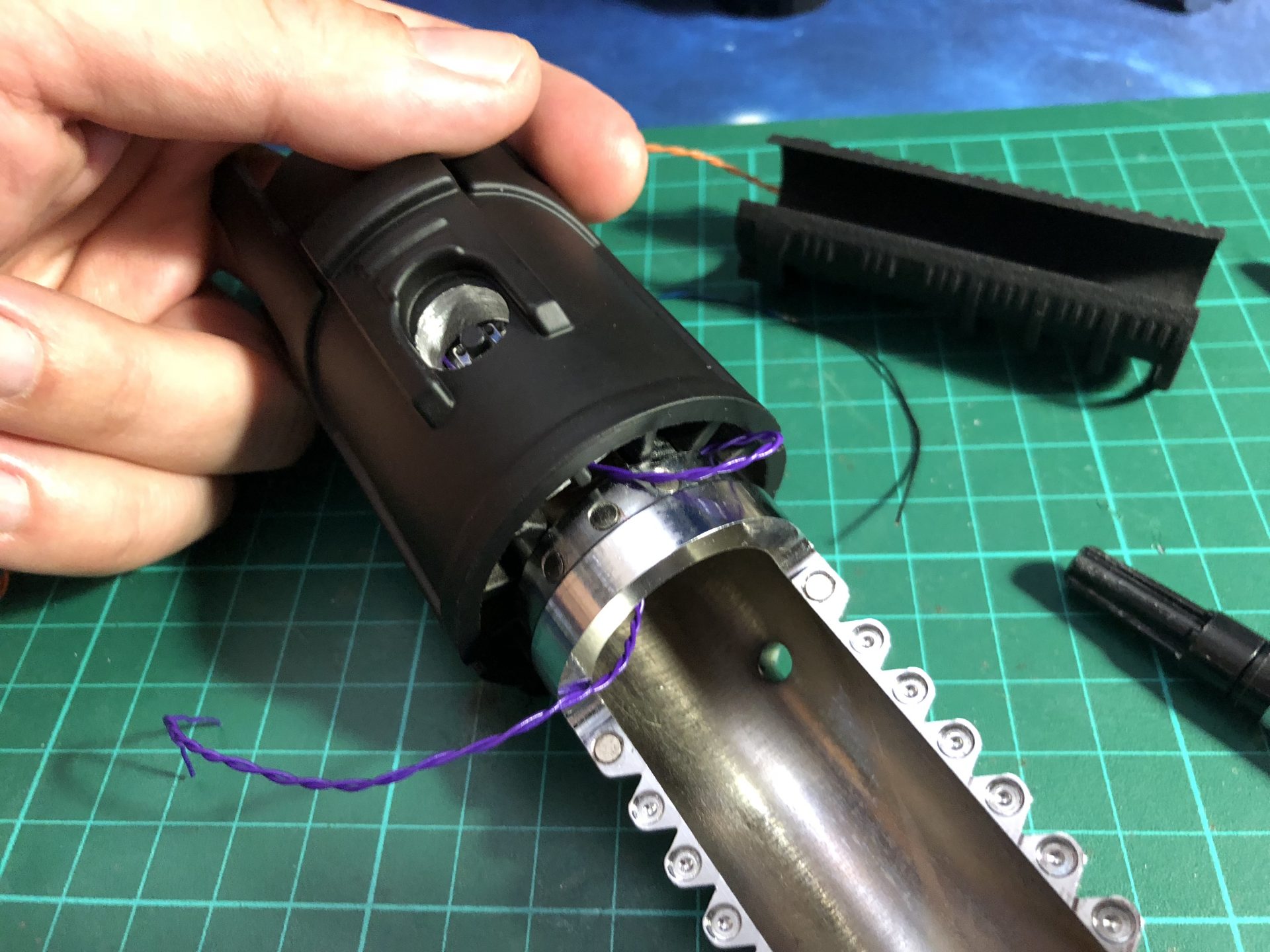
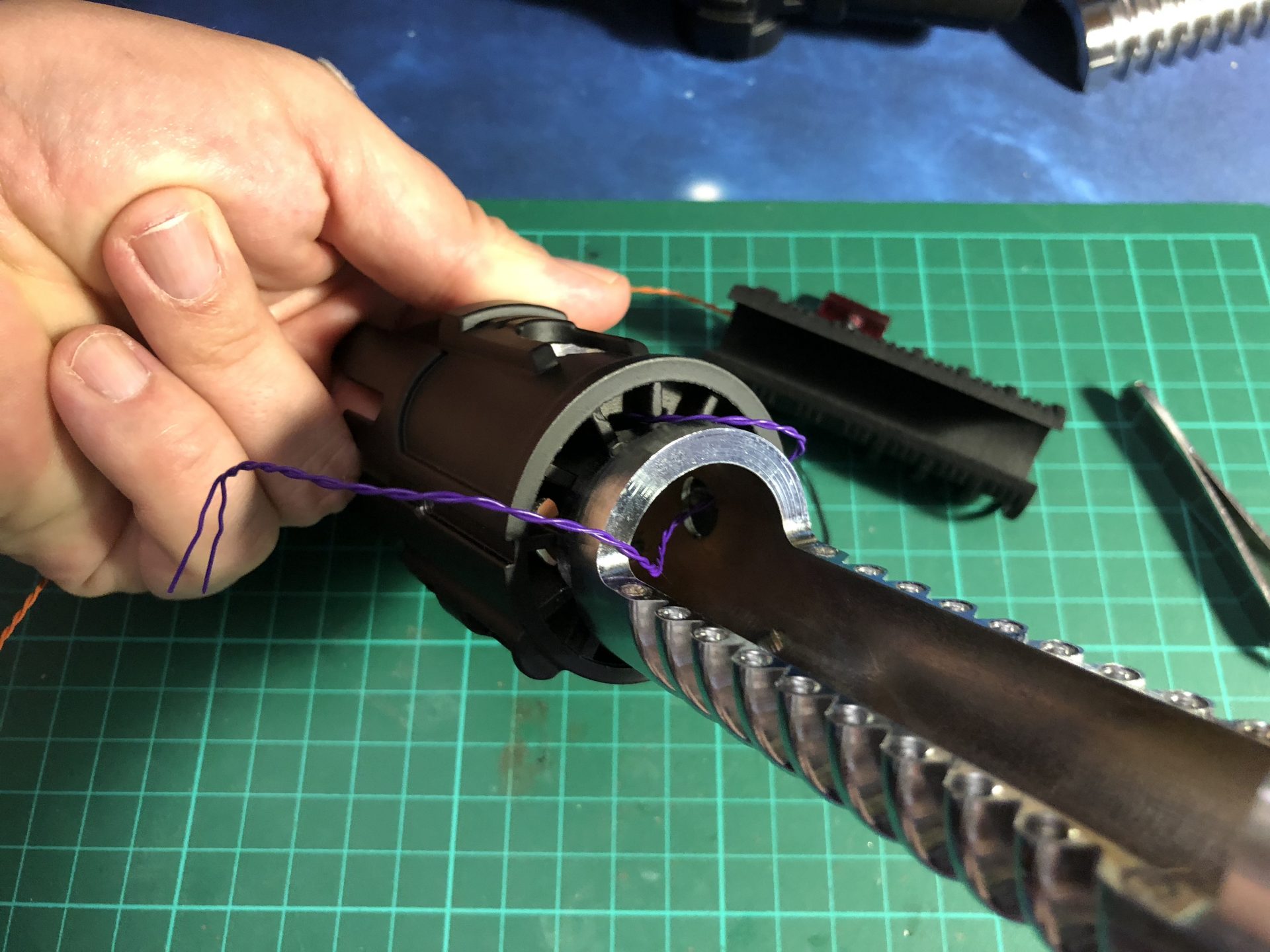
Finish the CC assembly, adjust the rod length and add the battery module.
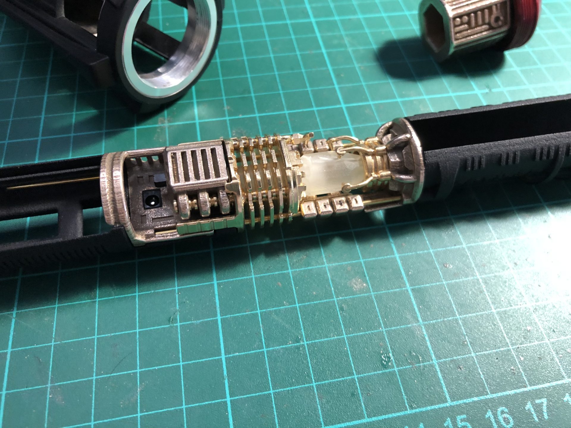
The CC assembly looks as shown below with all wires passing under it.