
These designs are no longer supported (FAQ)
Two chassis levels are available for the Imperial Knight Lightsaber:
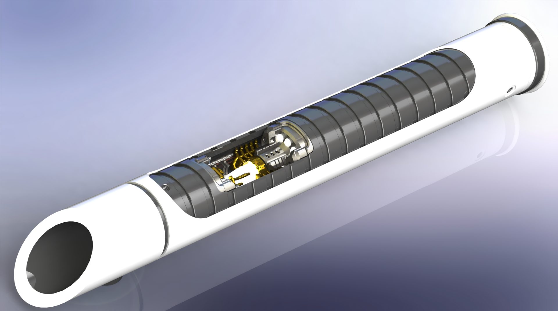
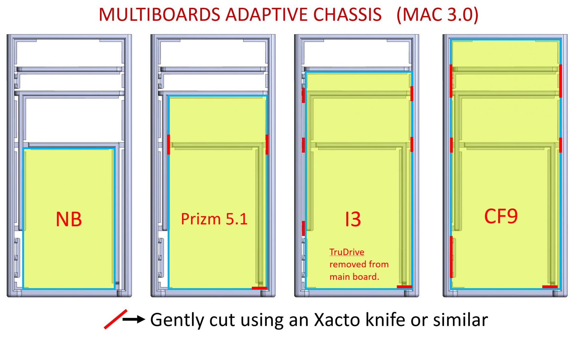
– Padawan for a basic install, with a chassis mainly focused on securing all your electronics. It has MultiBoards Adaptive Chassis to allow all major Plecter Labs and NEC soundboards to be installed (slot for CEx included).
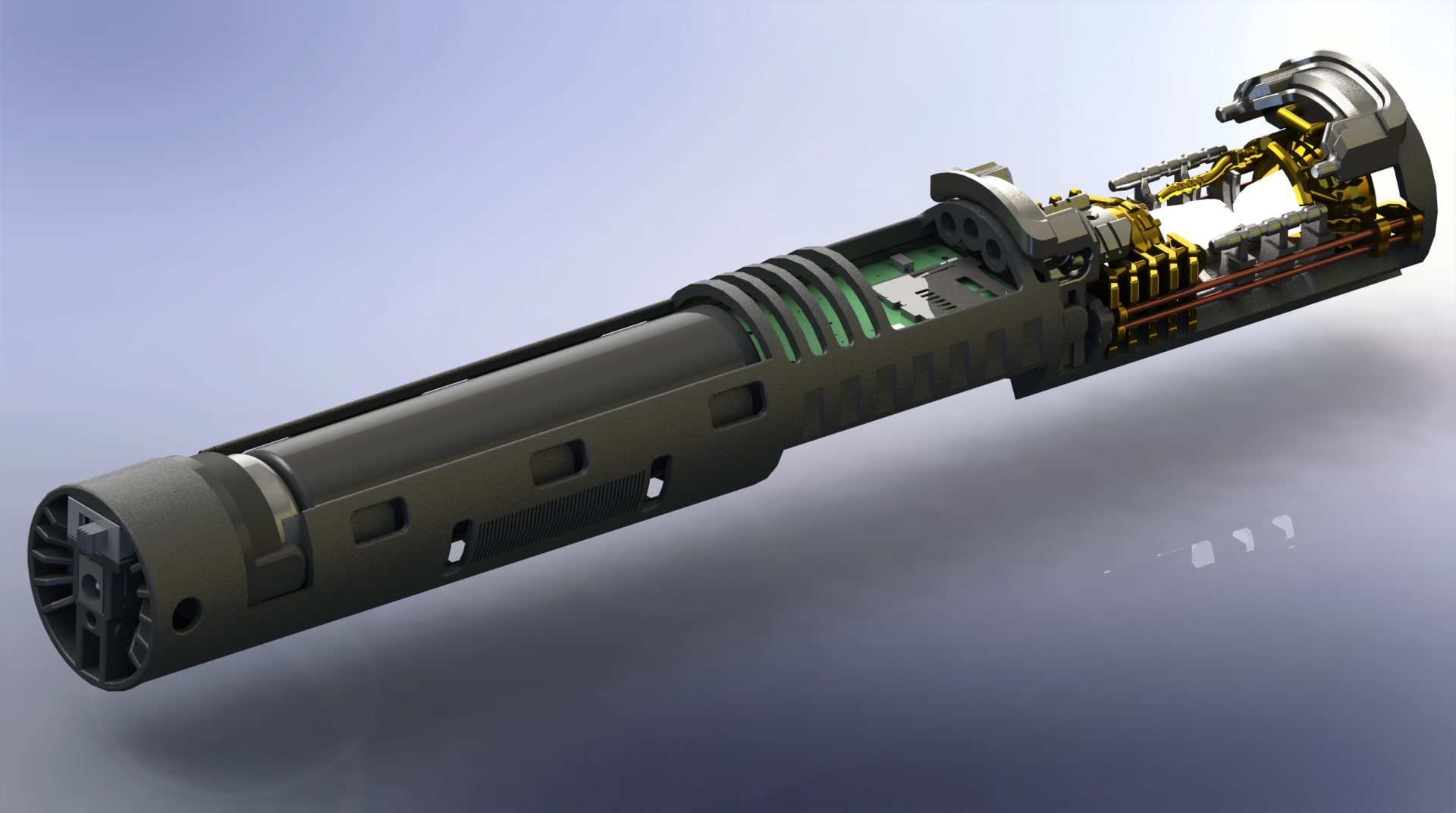
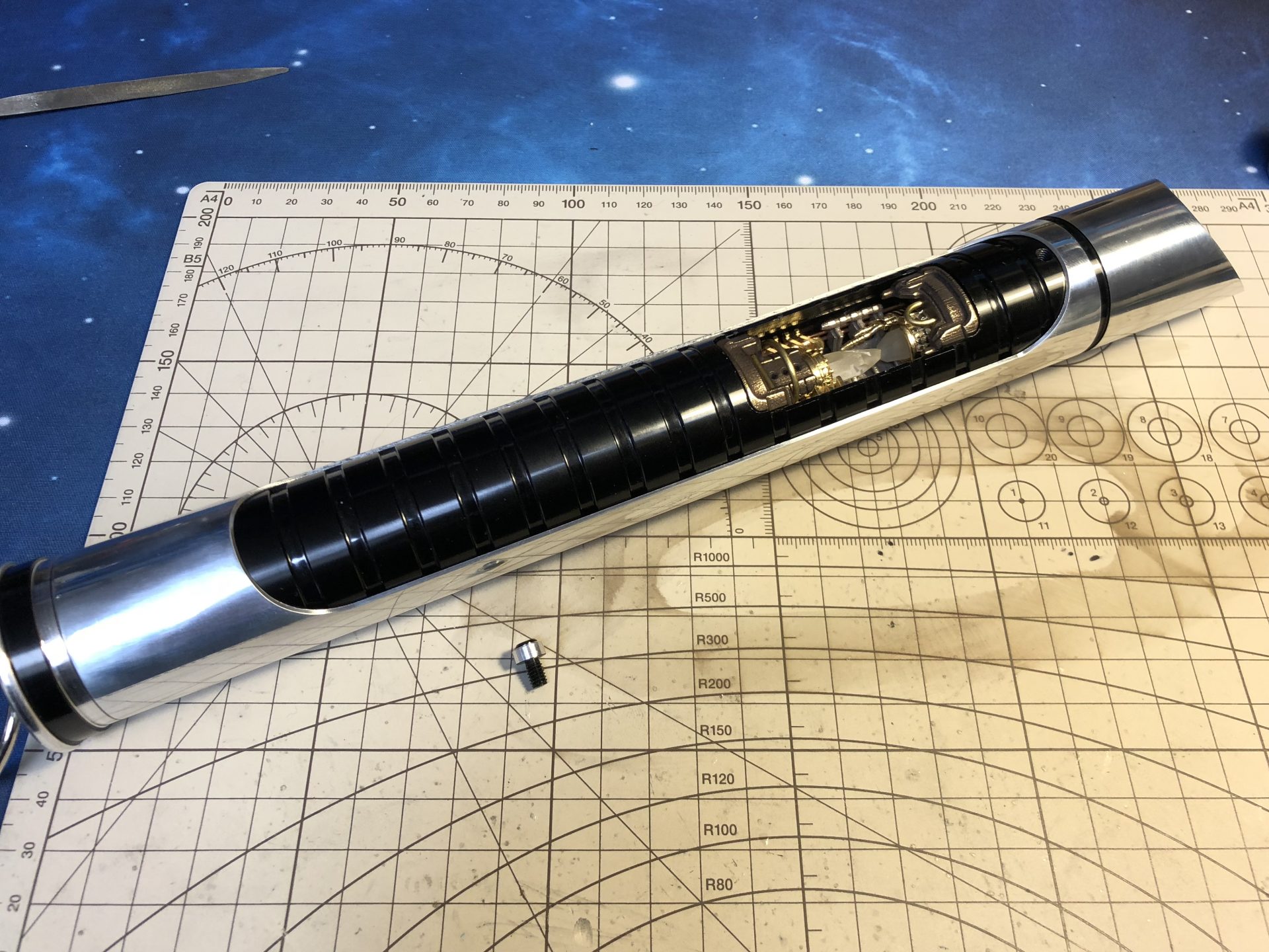
– Master with crystal chamber parts that can be printed in metal for the best reveal effect. Exists in various style according to the soundboard chosen.
Master:
Style1 => Plecter Prizm5.1 / NB
⇒ Part 1 Style 1 – imperial-knight-master-part1-style1
⇒ Part 2 – imperial-knight-master-part2
⇒ Part 3 Style 1 – imperial-knight-master-part3-style1
⇒ Part 4 Style 1 – imperial-knight-master-part4-style1
⇒ Part 5 – imperial-knight-master-part5
⇒ Part 6 Style 1 (optional crystals) – imperial-knight-master-part6-style1
Style2 => NEC I3
⇒ Part 1 Style 2 – imperial-knight-master-part1-style2
⇒ Part 2 – imperial-knight-master-part2
⇒ Part 3 Style 2 – imperial-knight-master-part3-style2
⇒ Part 4 Style 2 – imperial-knight-master-part4-style2
⇒ Part 5 – imperial-knight-master-part5
⇒ Part 6 Style 2 (optional crystals) – imperial-knight-master-part6-style2
Style3 => Plecter CF9
⇒ Part 1 Style 3 – imperial-knight-master-part1-style3
⇒ Part 2 – imperial-knight-master-part2
⇒ Part 3 Style 1 – imperial-knight-master-part3-style1
⇒ Part 4 Style 1 – imperial-knight-master-part4-style1
⇒ Part 5 – imperial-knight-master-part5
⇒ Part 6 Style 1 (optional crystals) – imperial-knight-master-part6-style1
Padawan:


⇒ Main chassis – imperial-knight-padawan-lightsaber-chassis
Additional chassis parts:
Most of the chassis parts needed for our chassis are available at The Saber Armory.
Local hobby stores or online store (as well as eBay) are a good source for parts.
You can also be inventive and add any custom parts, wire mesh, paint job or else to your chassis to give it an unique look!
For the Master chassis only, here is a list of parts needed to install it:
⇒ 1.5mm OD rods
⇒ 1mm OD rods
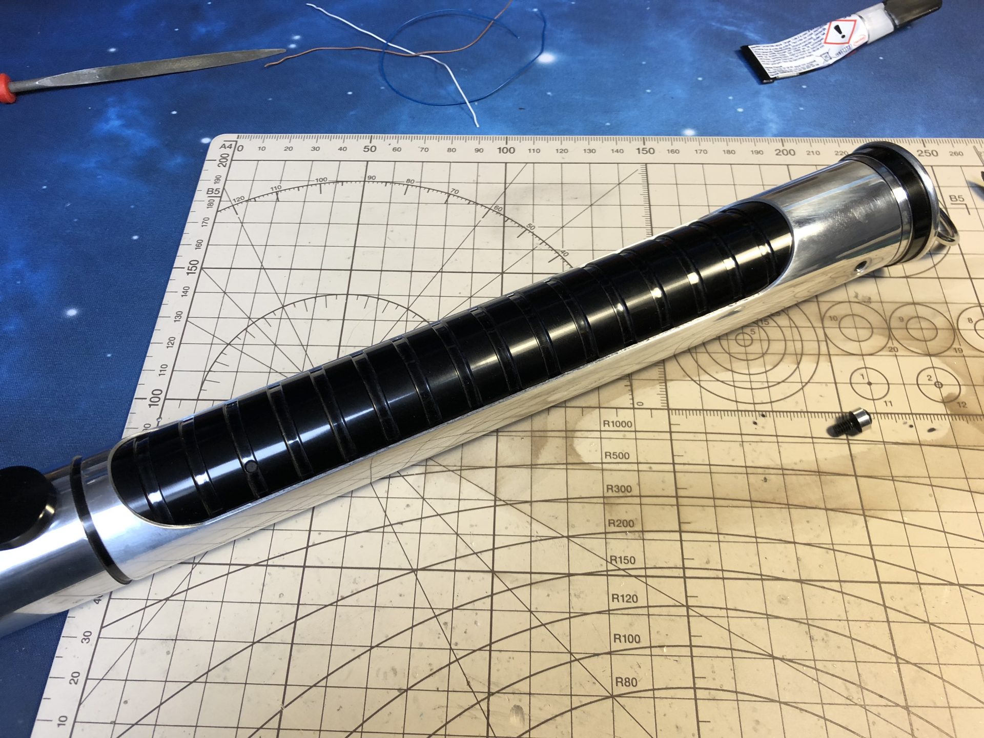
Quick Install Guide:
Disclainer:
– These instructions will details the install procedure as much as possible. GOTH-3Designs cannot be held responsible for any mistakes made by DIYers.
– Always wear protective gear when working on install (gloves, eye protection, …), GOTH-3Designs cannot be held responsible in case of accident.
Note 1: 30awg wires and smaller are mandatory for this install (30awg for main wires and 32awg for accent leds and switches are highly recommended)…. Oh and definitely use colored wires to make your life easier.
Note 2: These instructions will not cover how to wire the soundboard, make sure to learn how to by reading the manual. make sure to test your install along the way! Checking everything works after important steps is better than having to dismount everything cause something wasn’t wired properly.
Note 3: Recharge port wiring reminder:

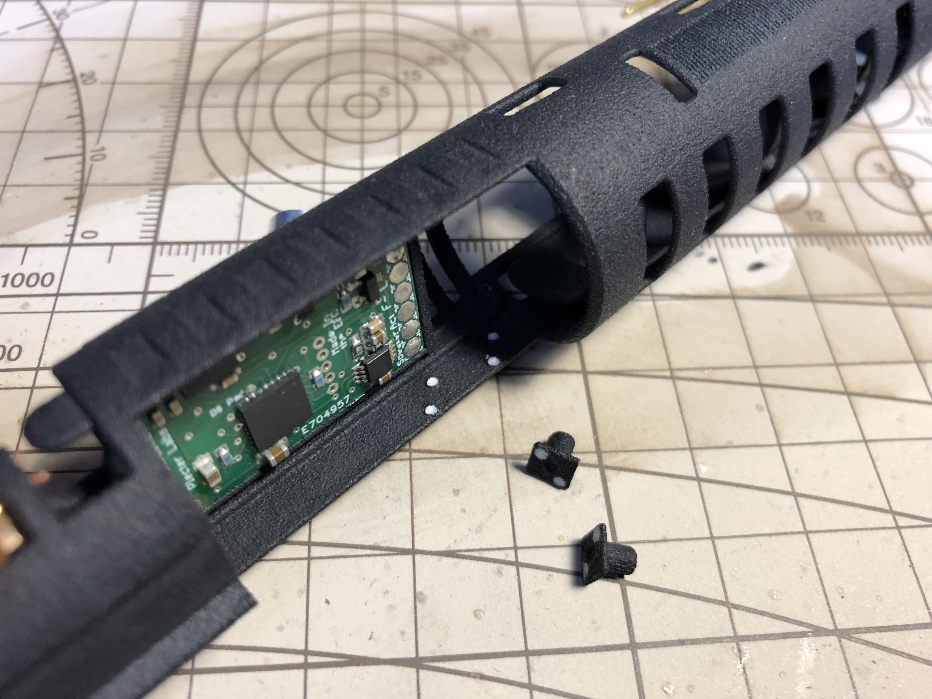
Note 5: Multiboard adaptive chassis (Padawan).
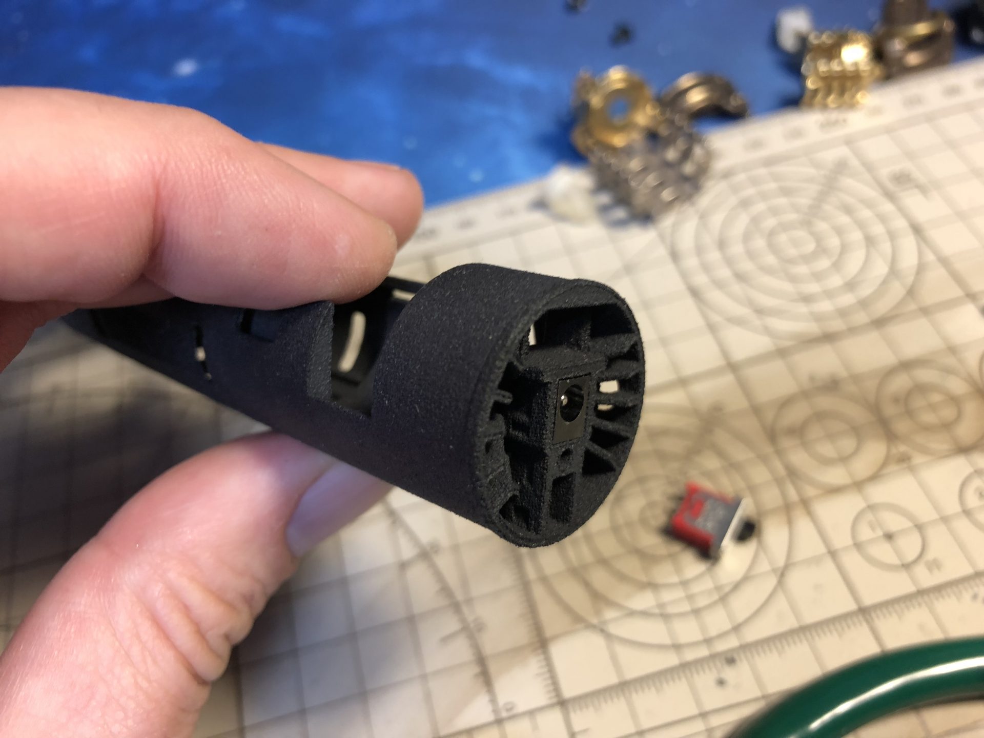
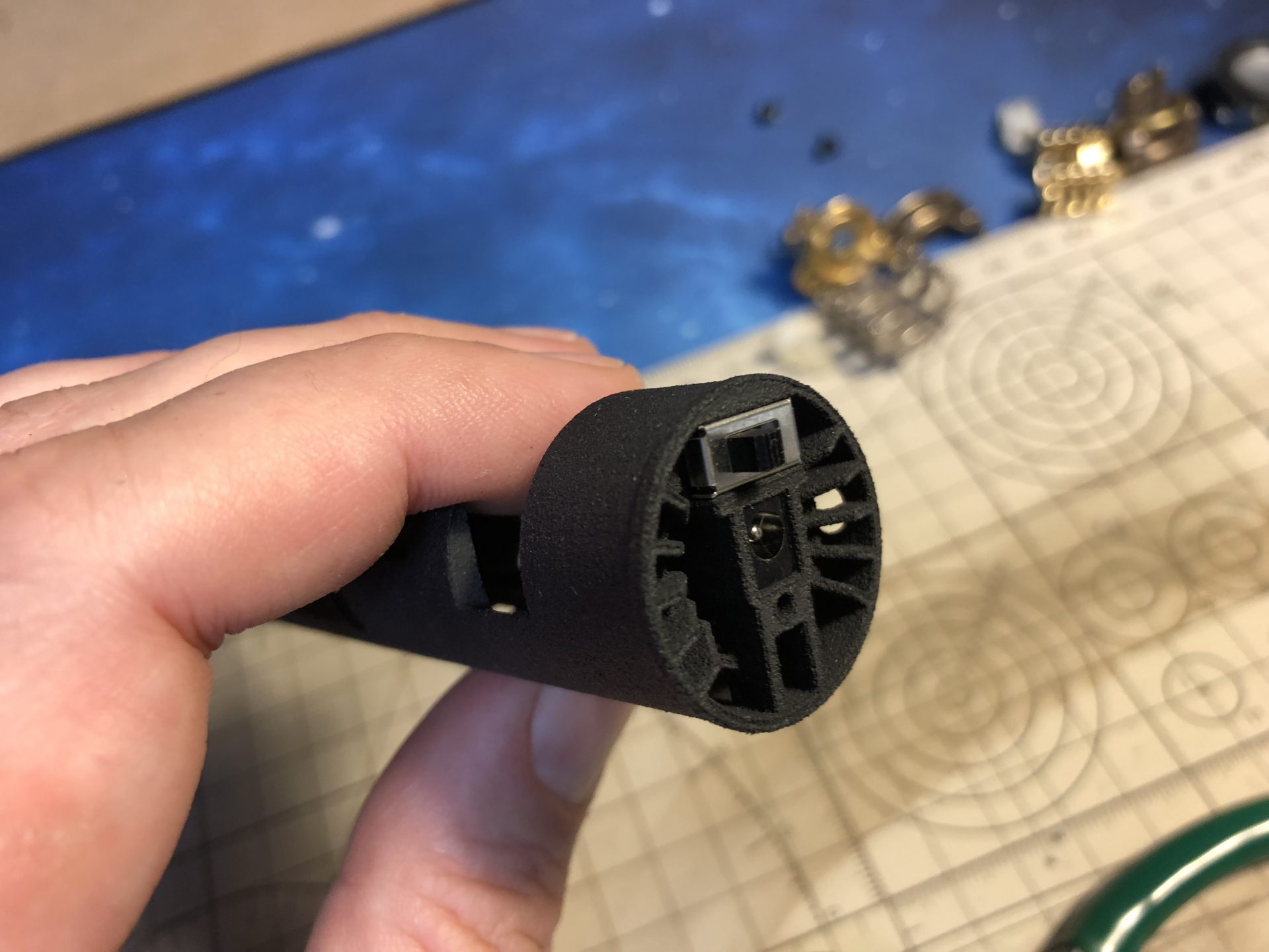
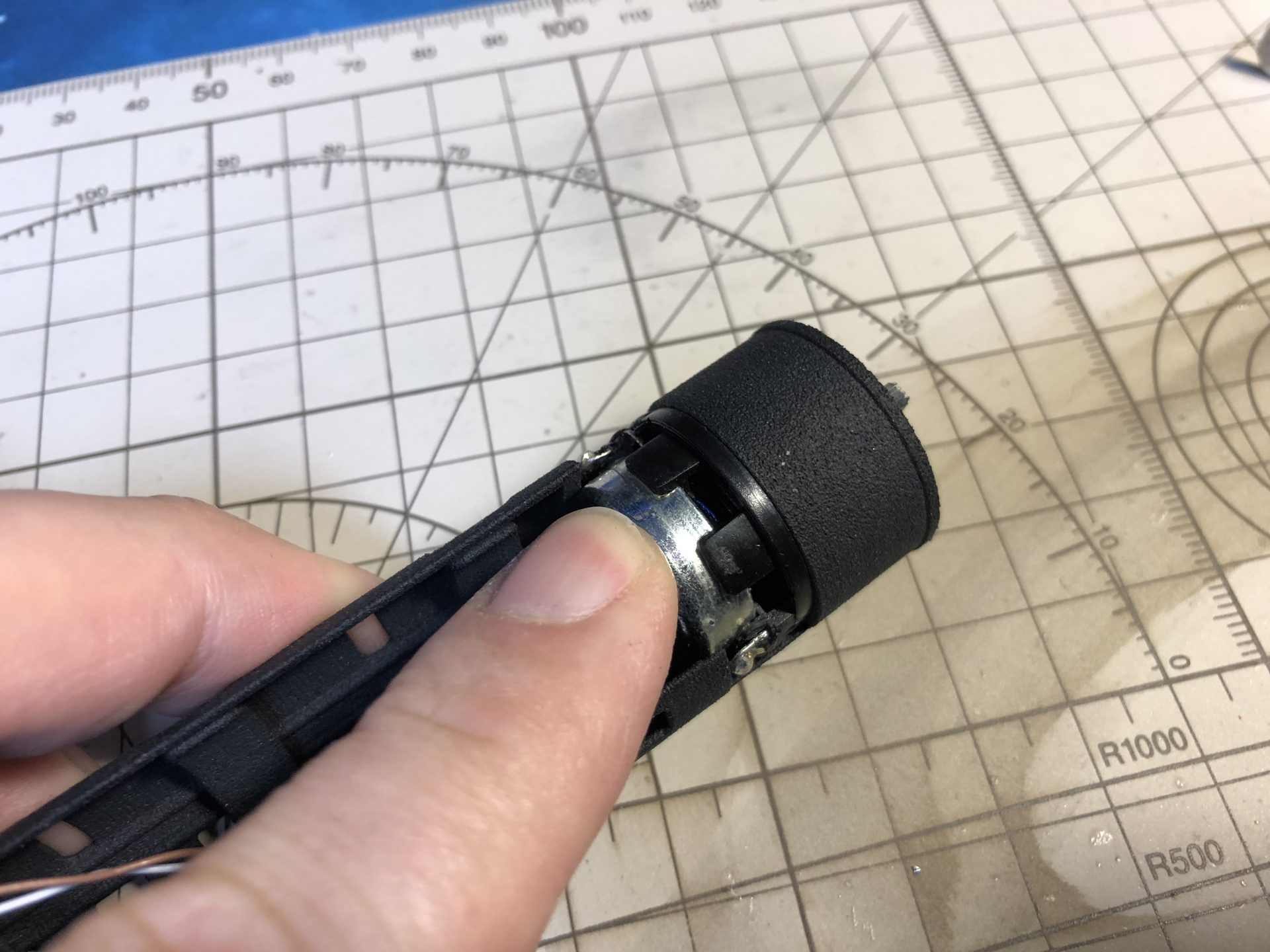
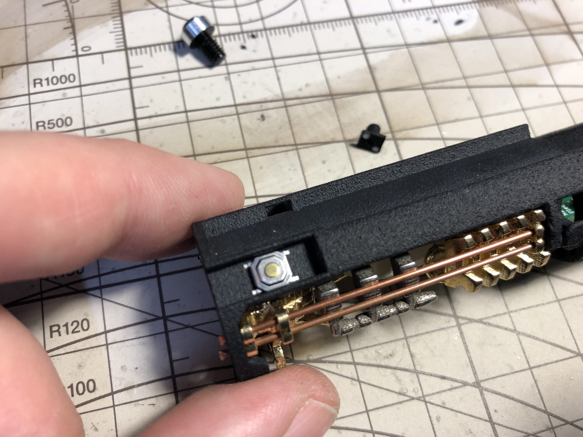
The 1.3mm recharge port and kill switch are installed on the back of the chassis first.
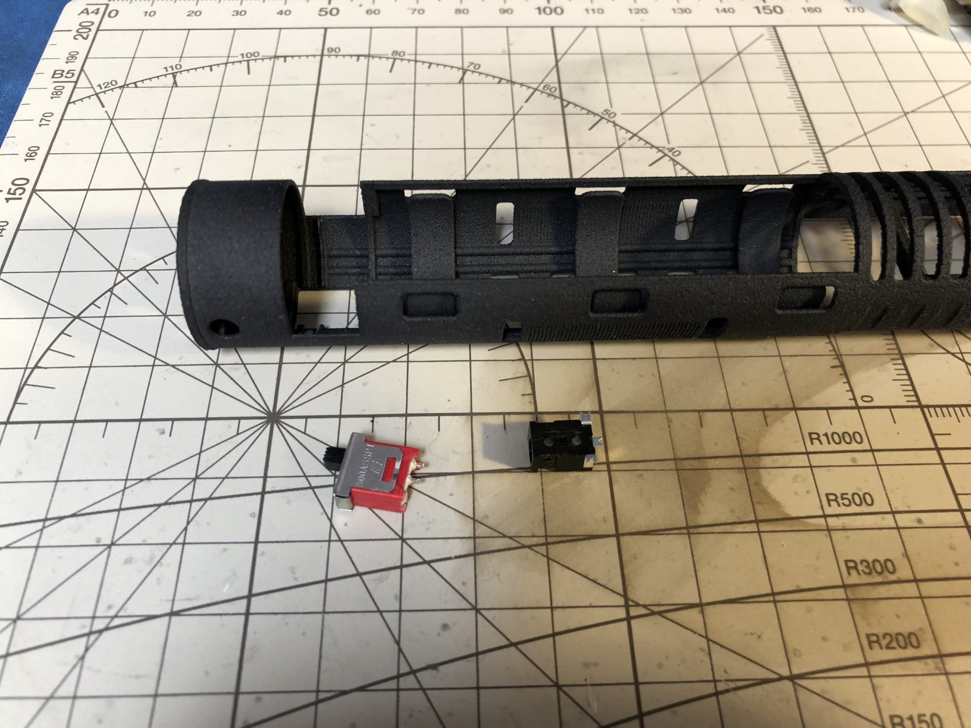
Space is limited, as the 24mm speaker will be installed just behind them. It is necessary to cut a bit the recharge port back prong, as well as the kill switch prongs and have the wires soldered perpendicularly to them so that they will not come in conflict with the speaker.
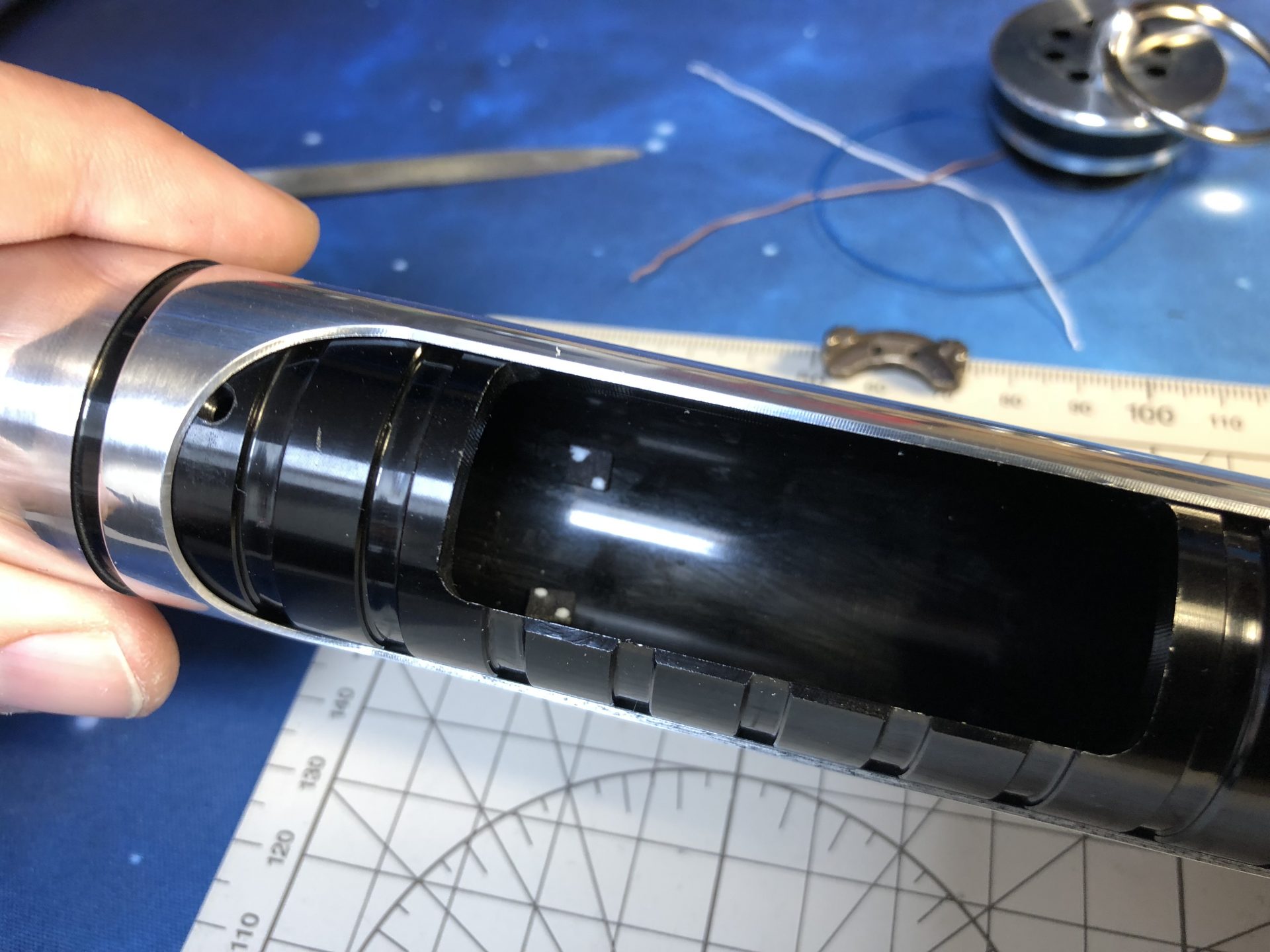
The speaker must be glued as show below. There is a channel for wires to pass under it (it is recommended to have these wires pass all the way through the battery slot).
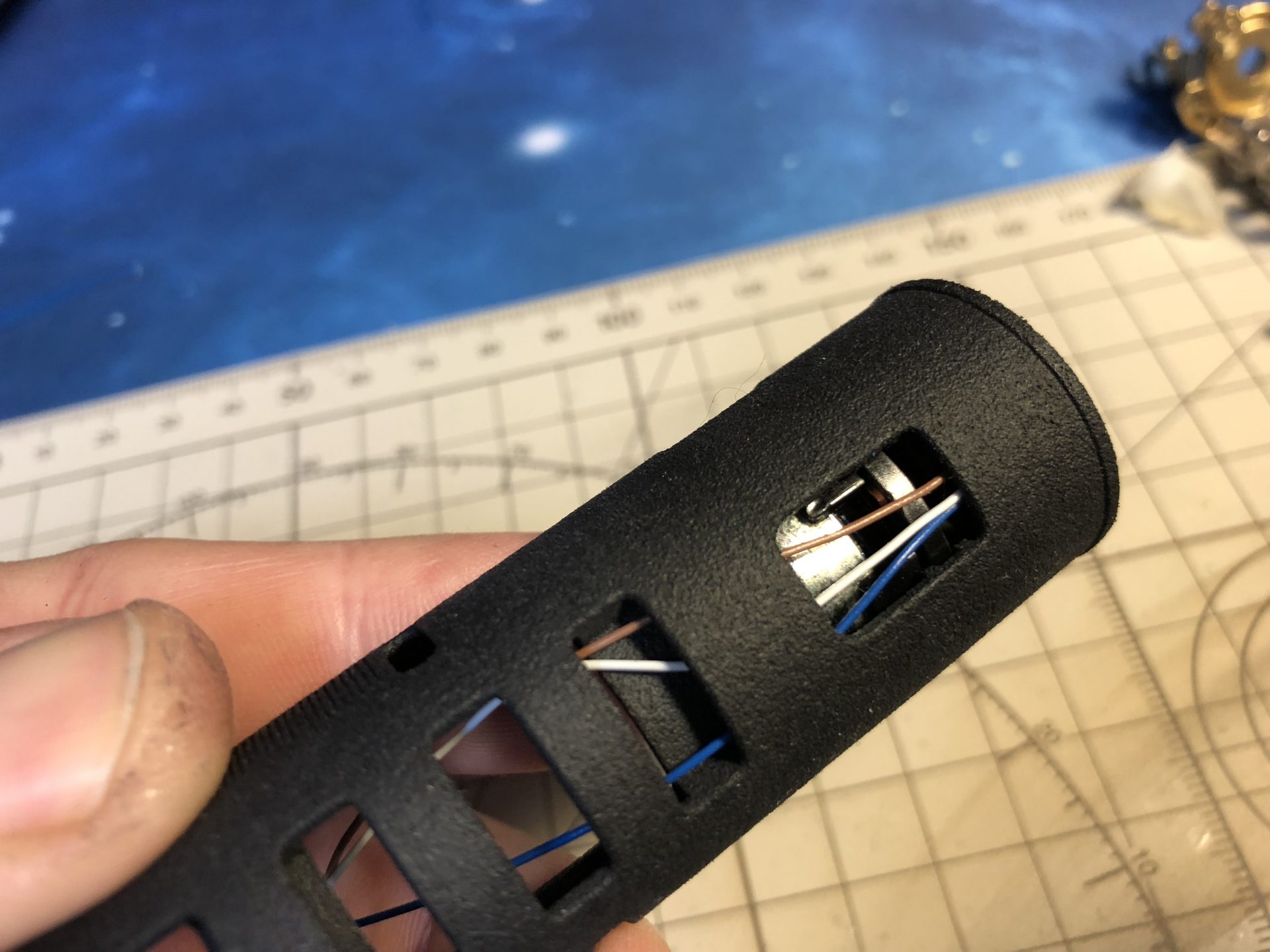
The battery can then be inserted (adding a bit of super glue will help securing it totally). It is recommended to have the battery wires exiting and soldered to the recharge port wires on the soundboard side as there is more space there.
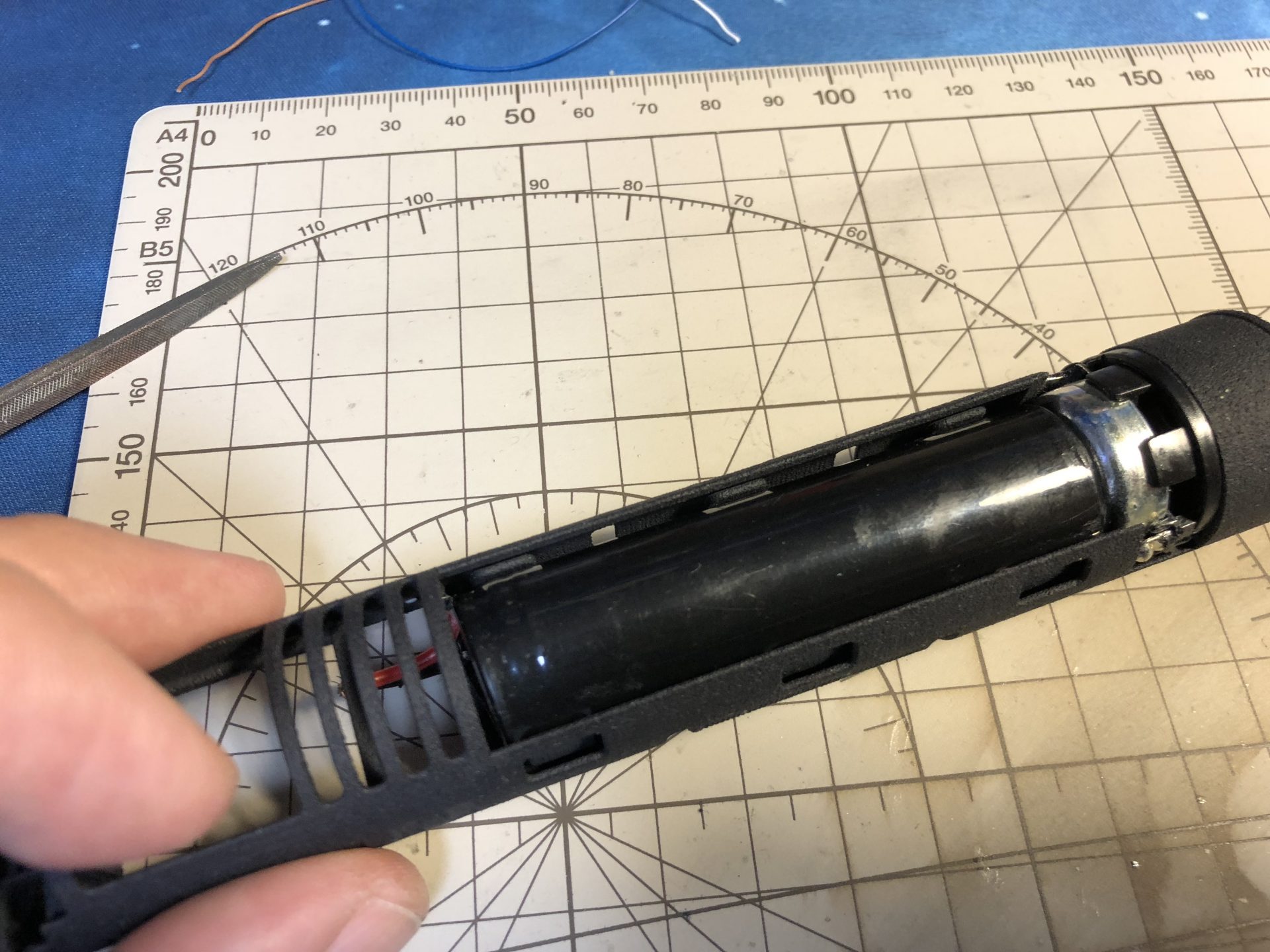
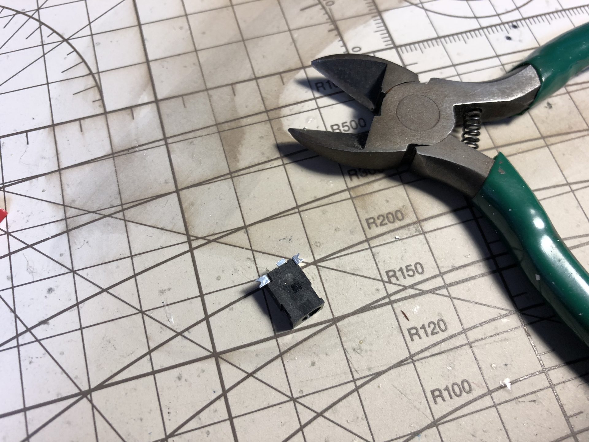
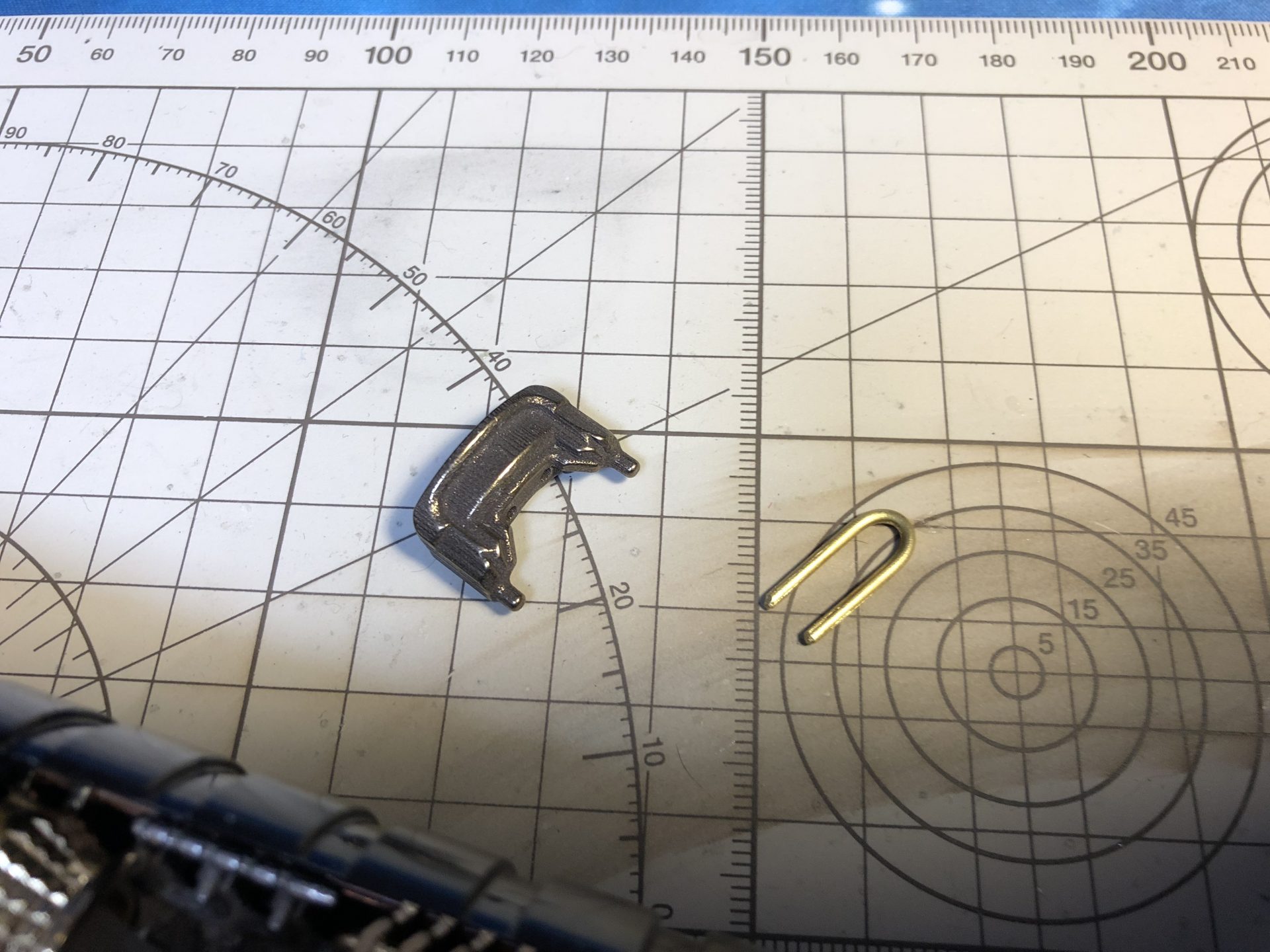
Switch plungers are attached to the chassis and have to be cut away before installing the soundboard.
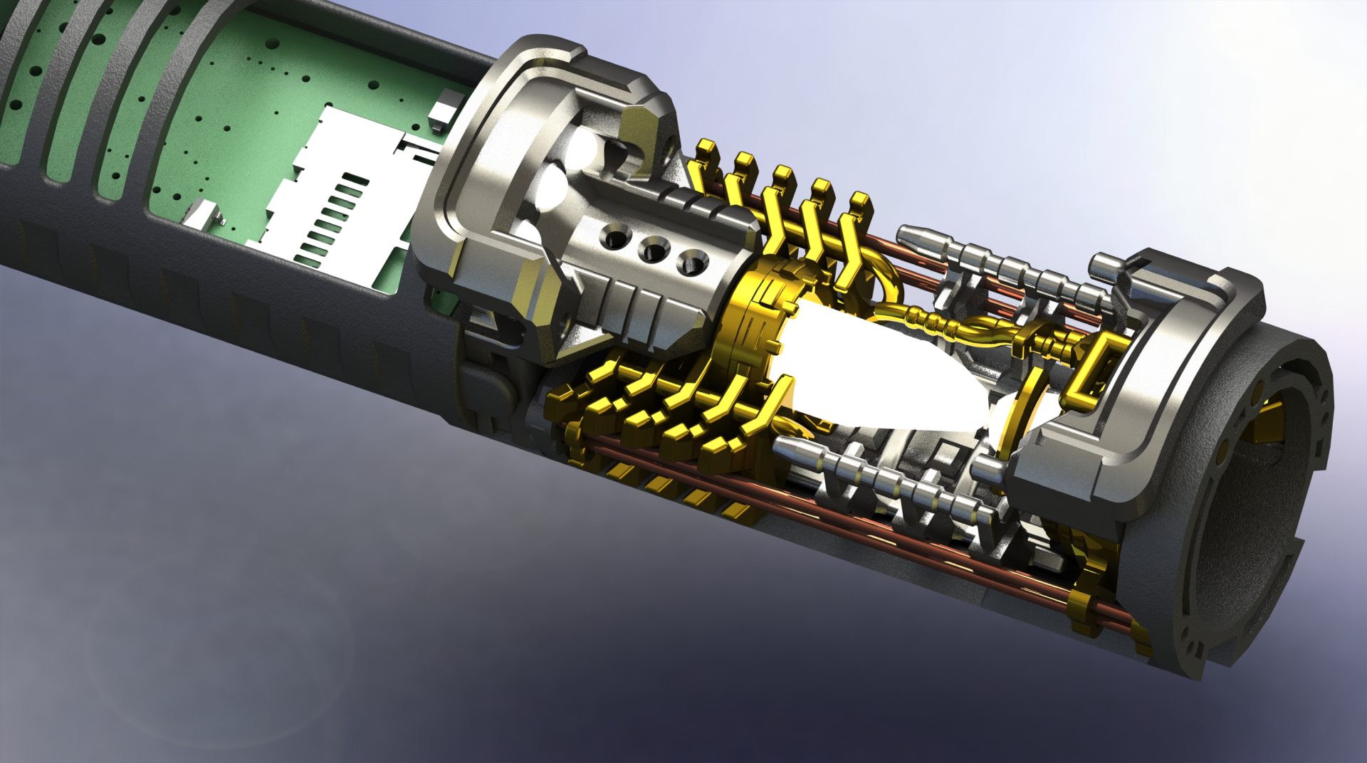
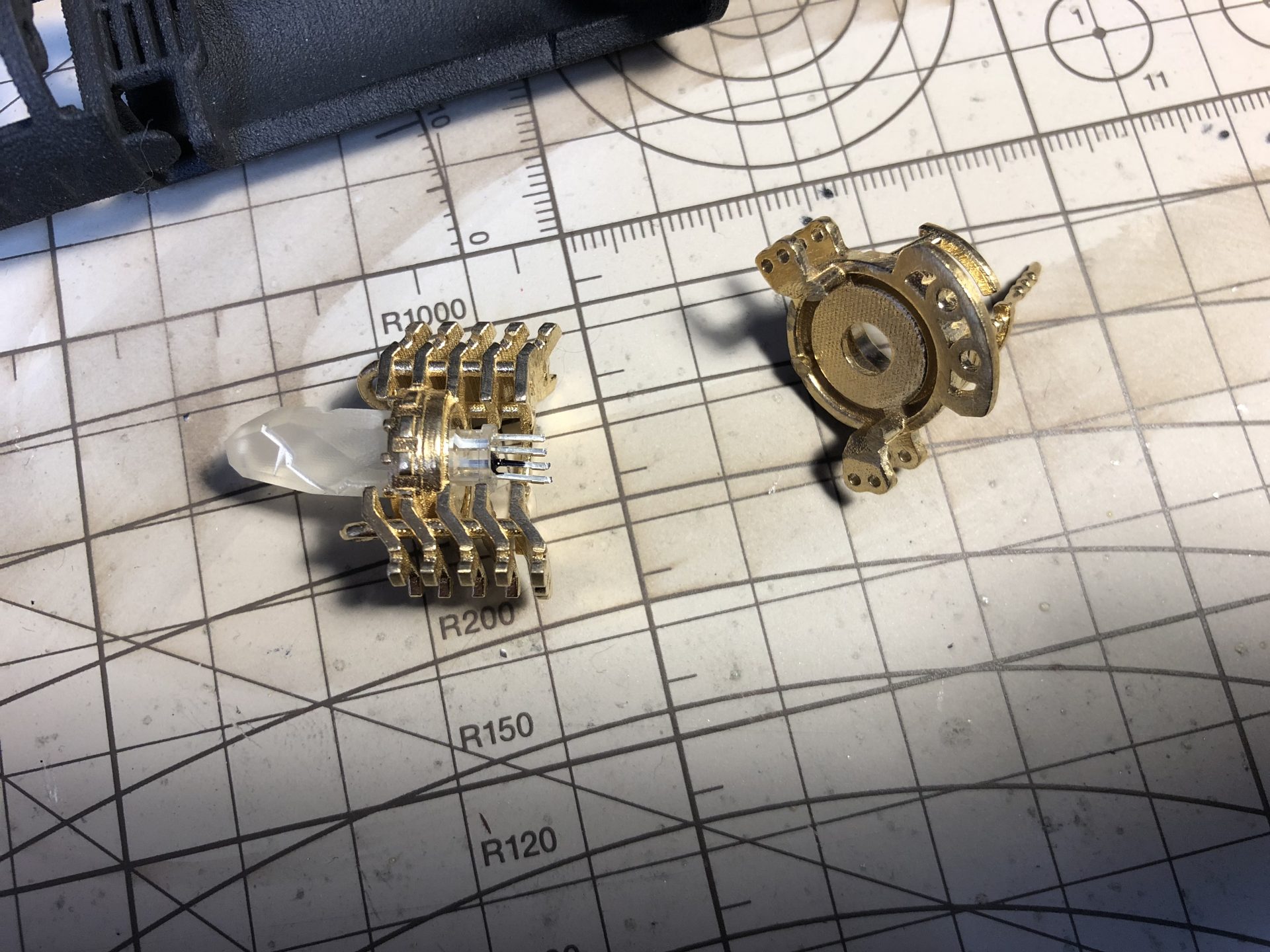
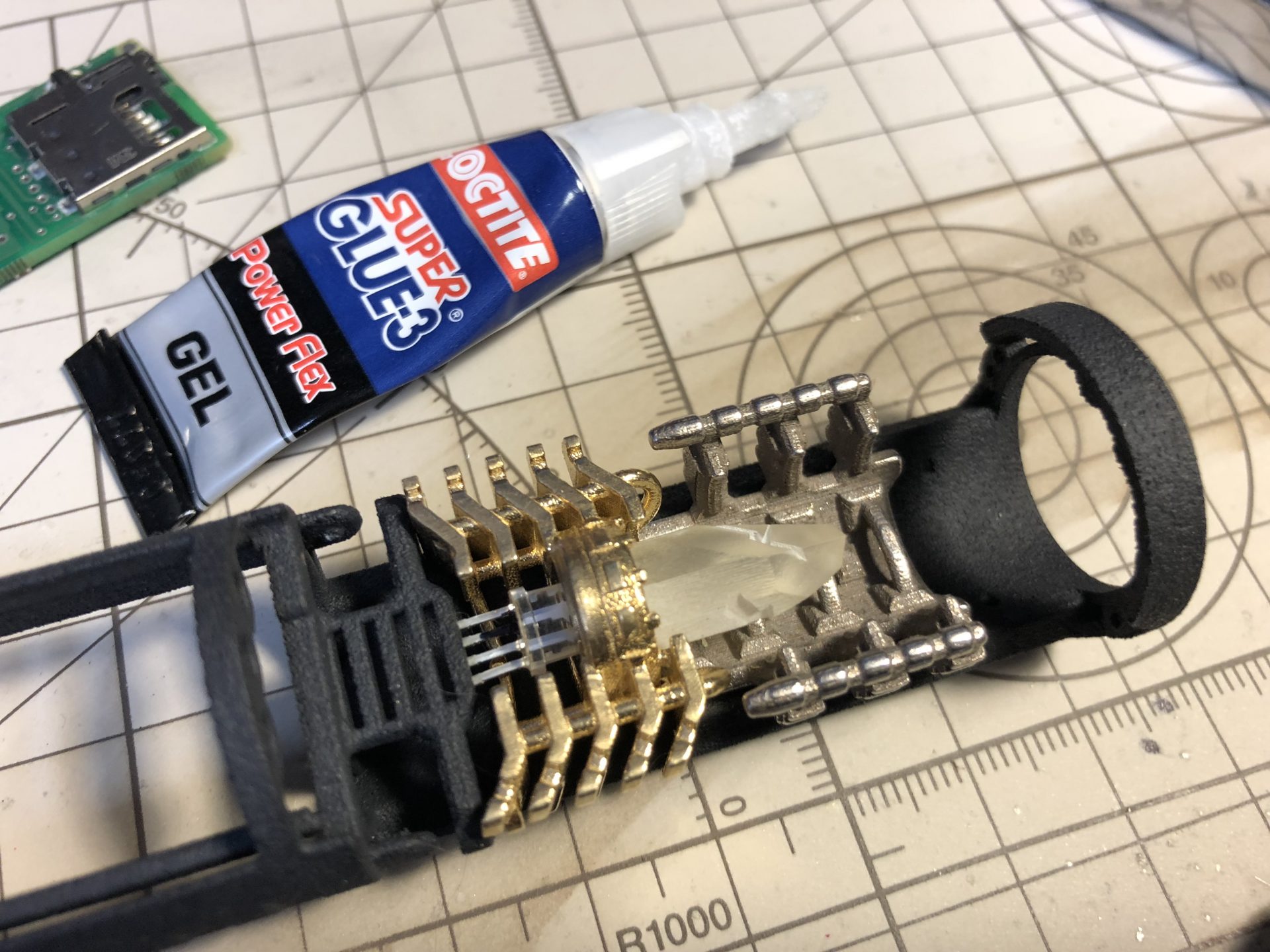
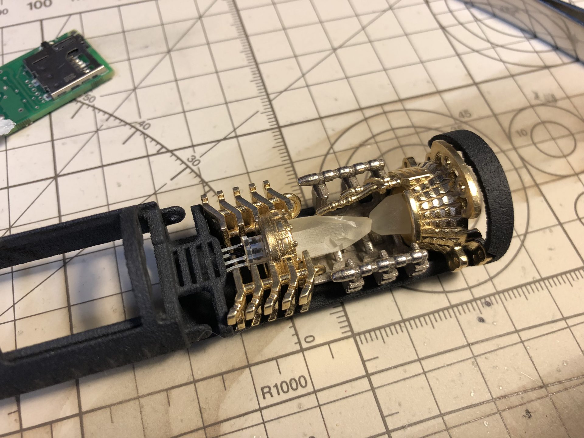
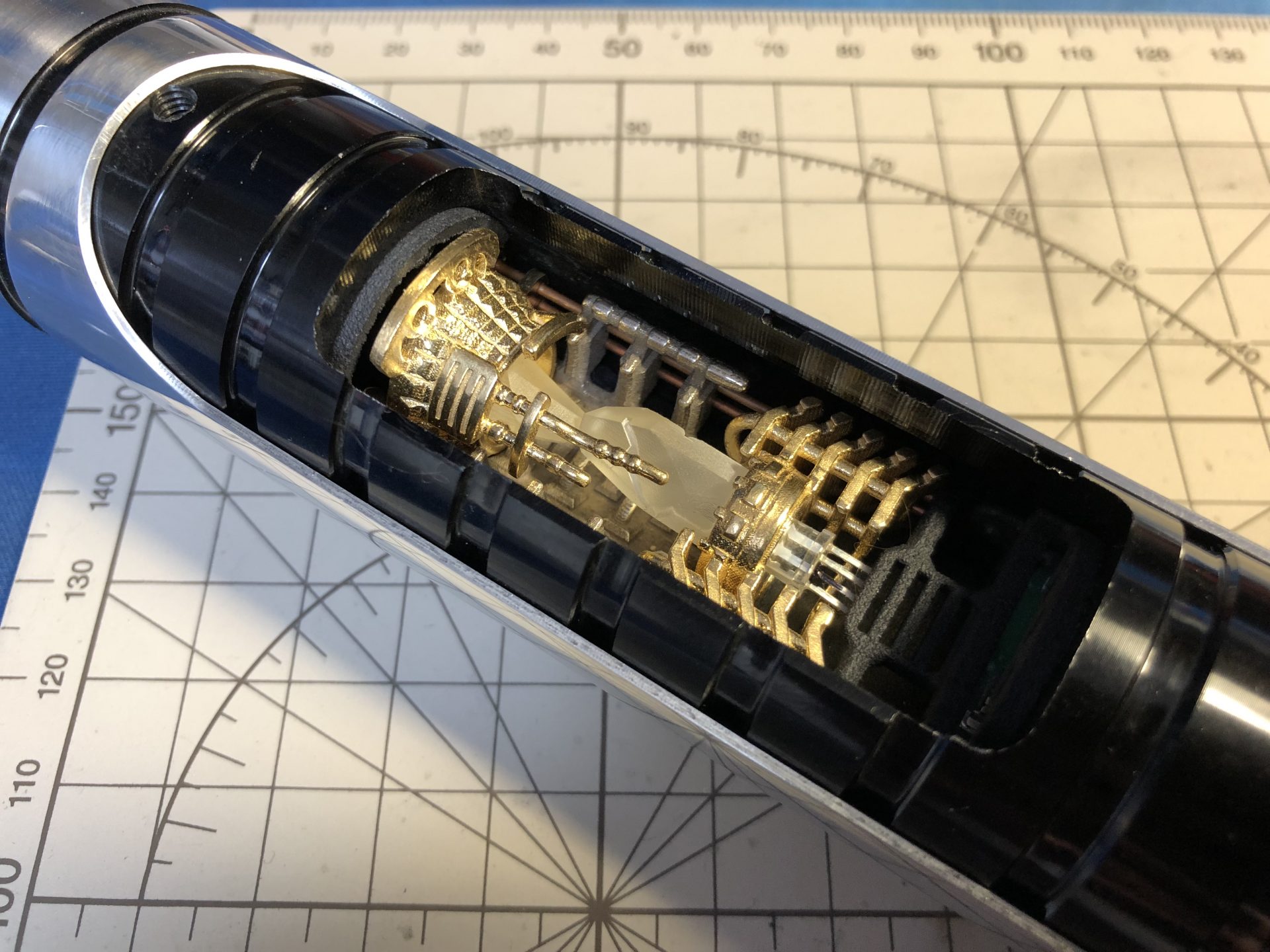
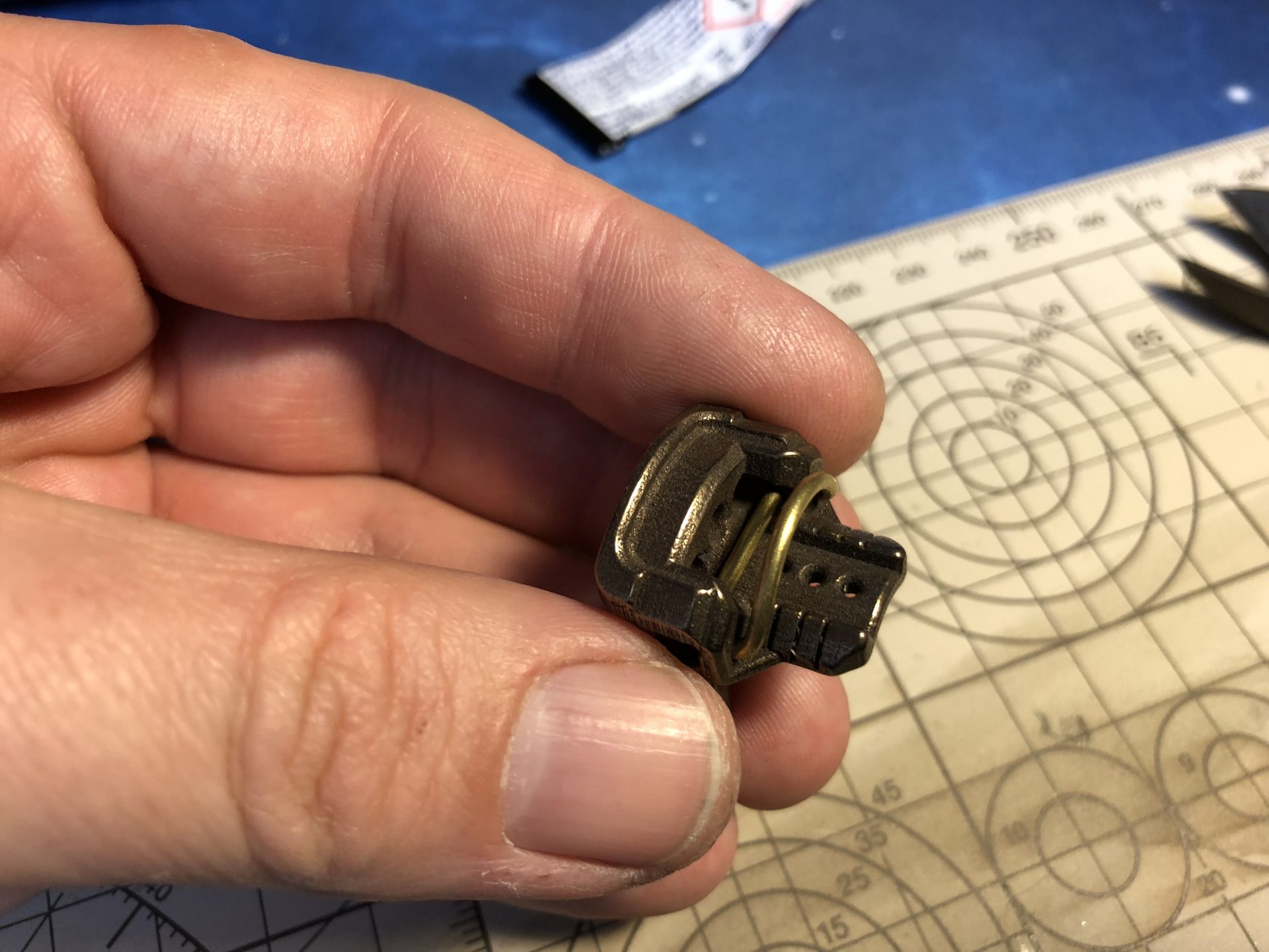
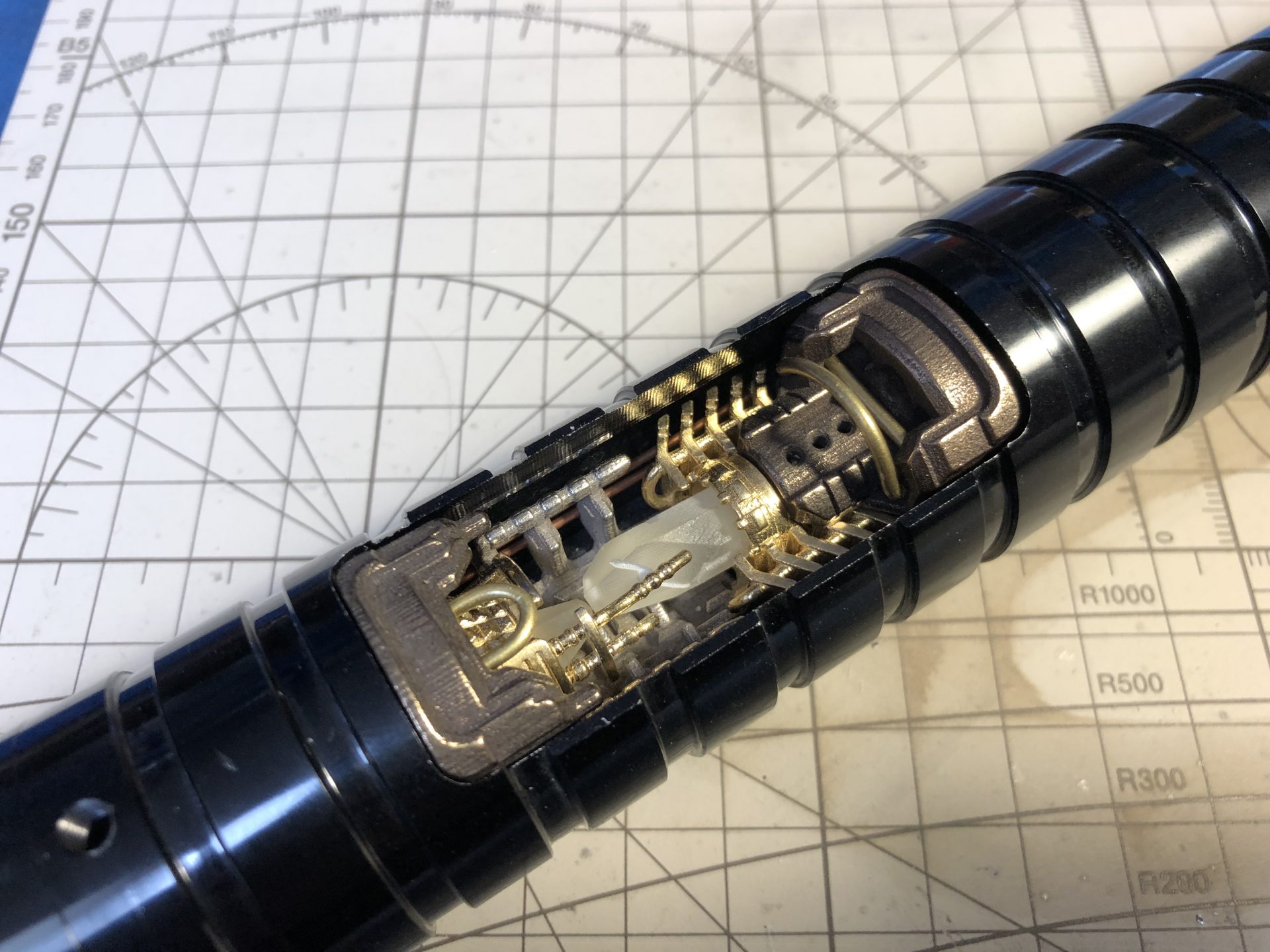
The crystal chamber inserts come attached together and need to be separated (cut). Crystal and accent led can then be installed on them as shown below:
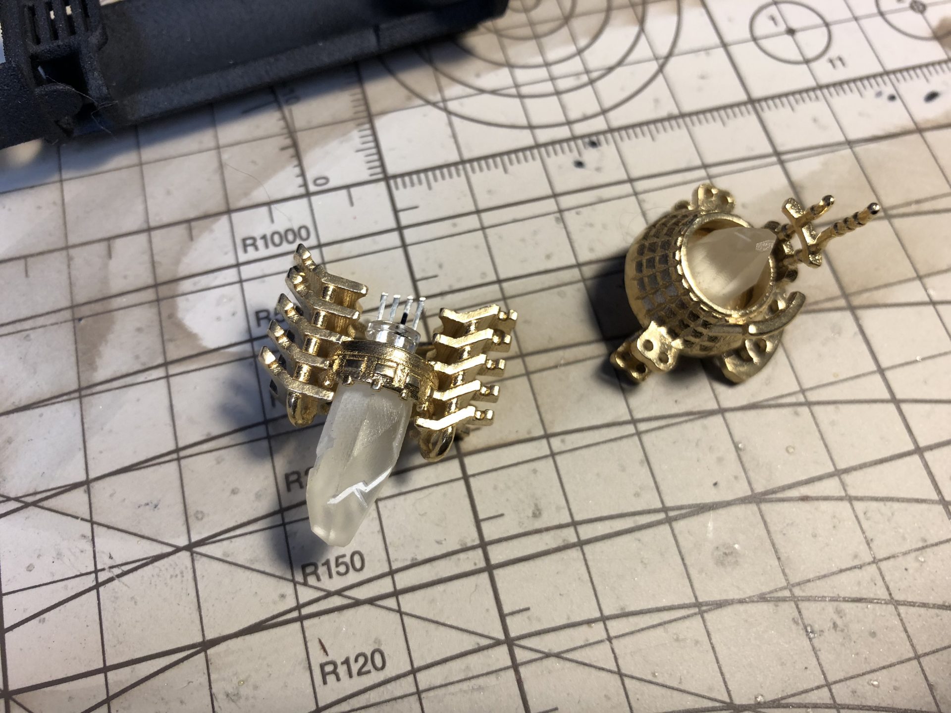
The Part 4 attaches to the first insert as follow, and can then be added into the chassis. Super glue can be used to secure the assembly.
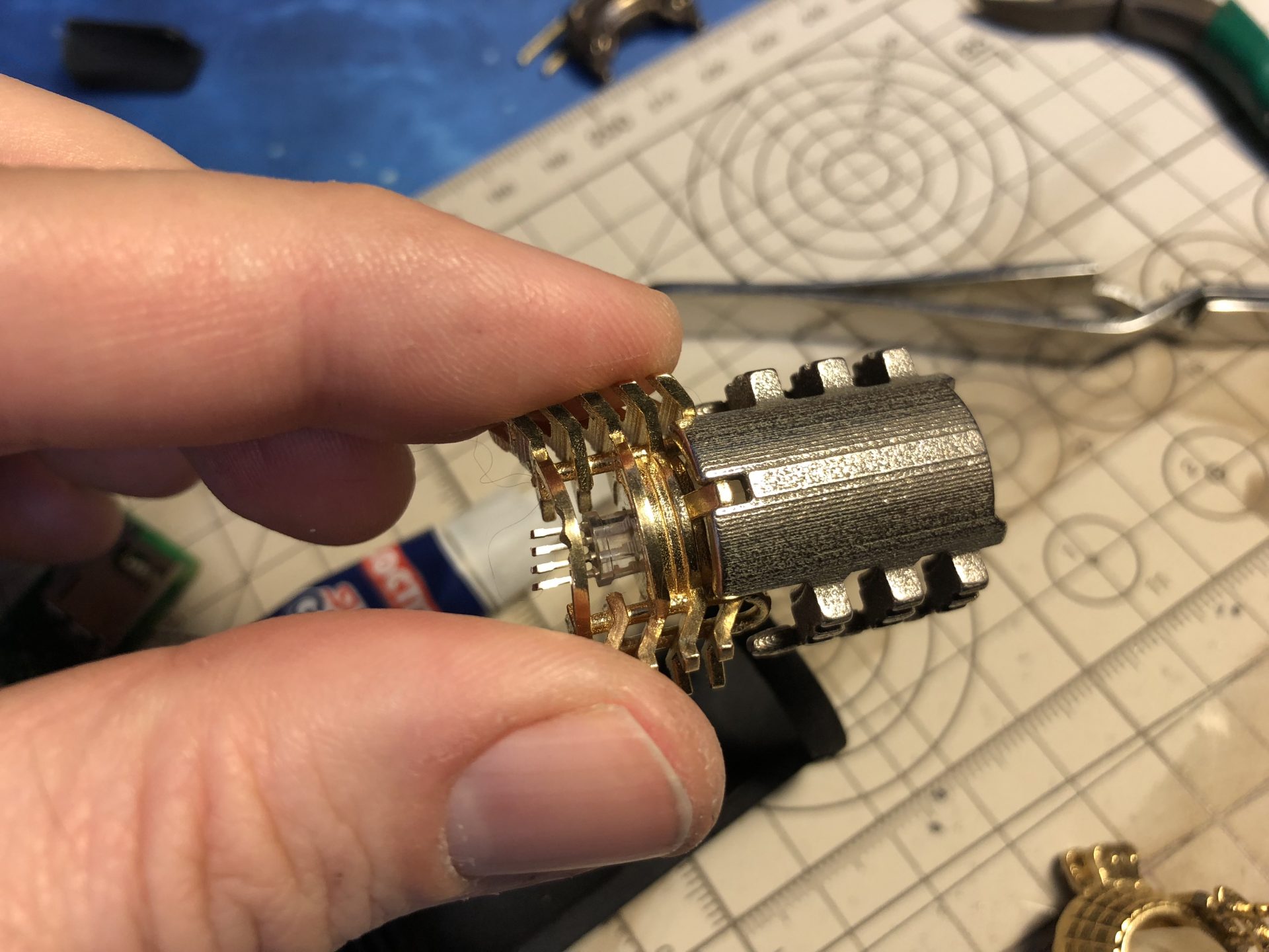
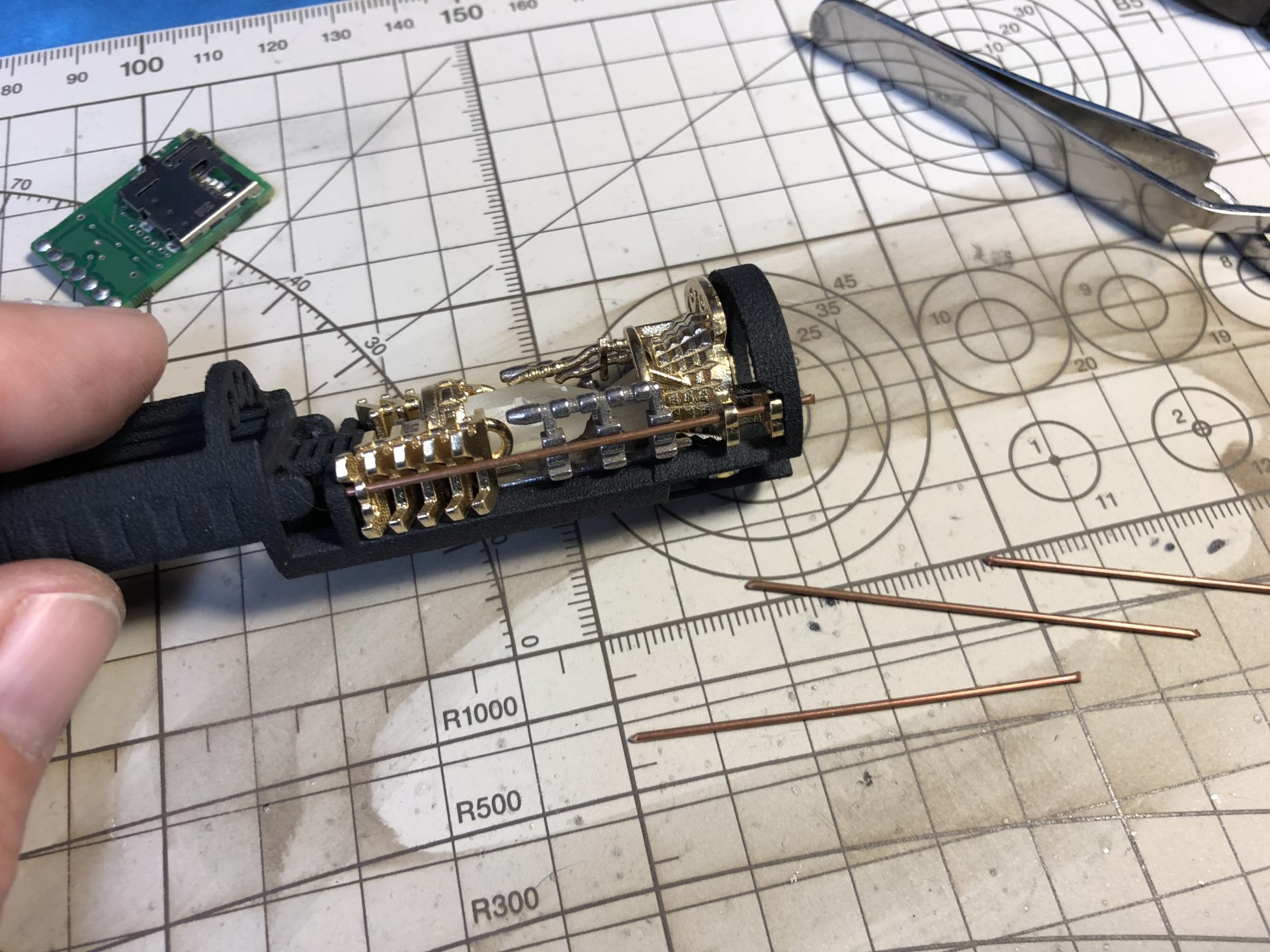
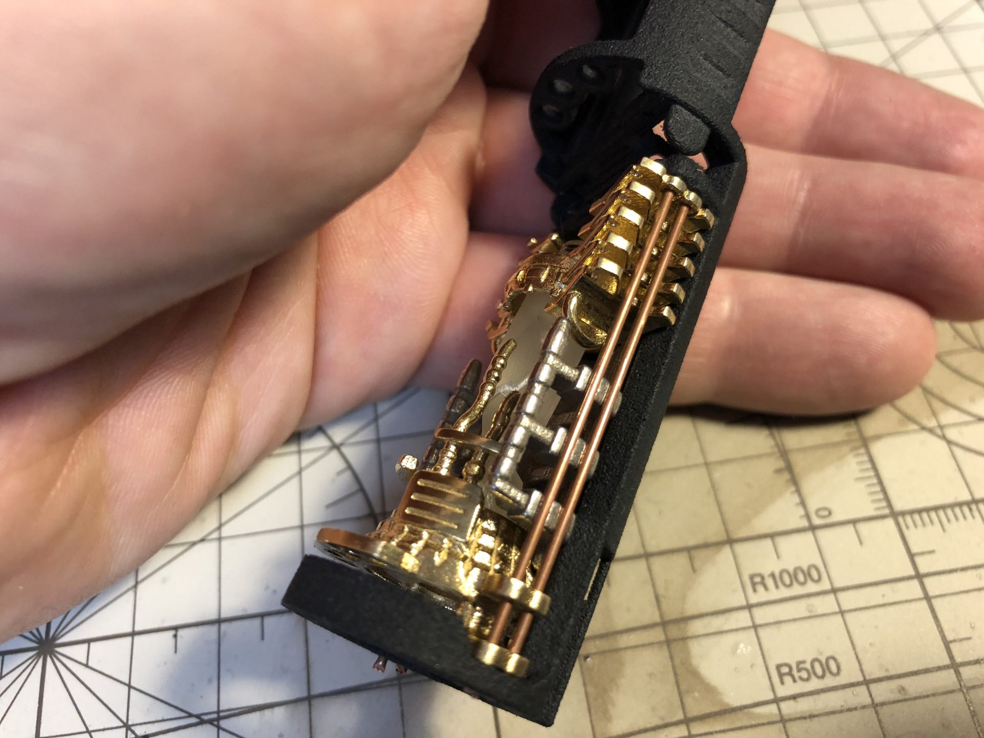
2nd insert is then added, with 1mmOD rods to align and secure everything (rods to be glued to the chassis)
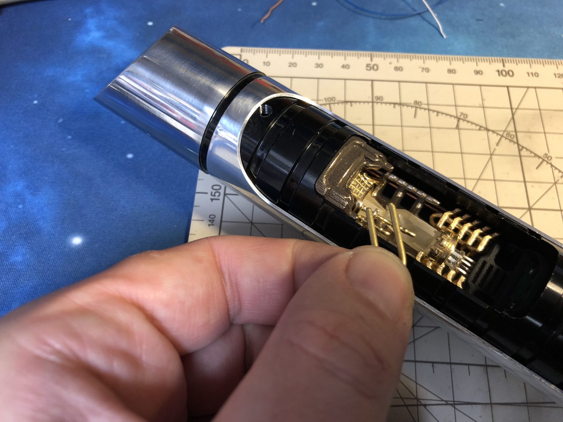
Insert the chassis temporarily into the hilt in order to mark where the 1.5mm height tactile switches need to be precisely placed on the chassis dedicated rail.
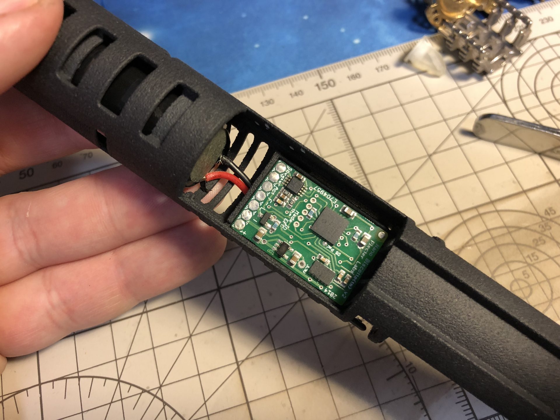
Once everything wired properly and tested, add the plungers and slowly insert the chassis back in (it takes a bit of time to keep the plungers well aligned when inserting the chassis – patience required). Then test again!
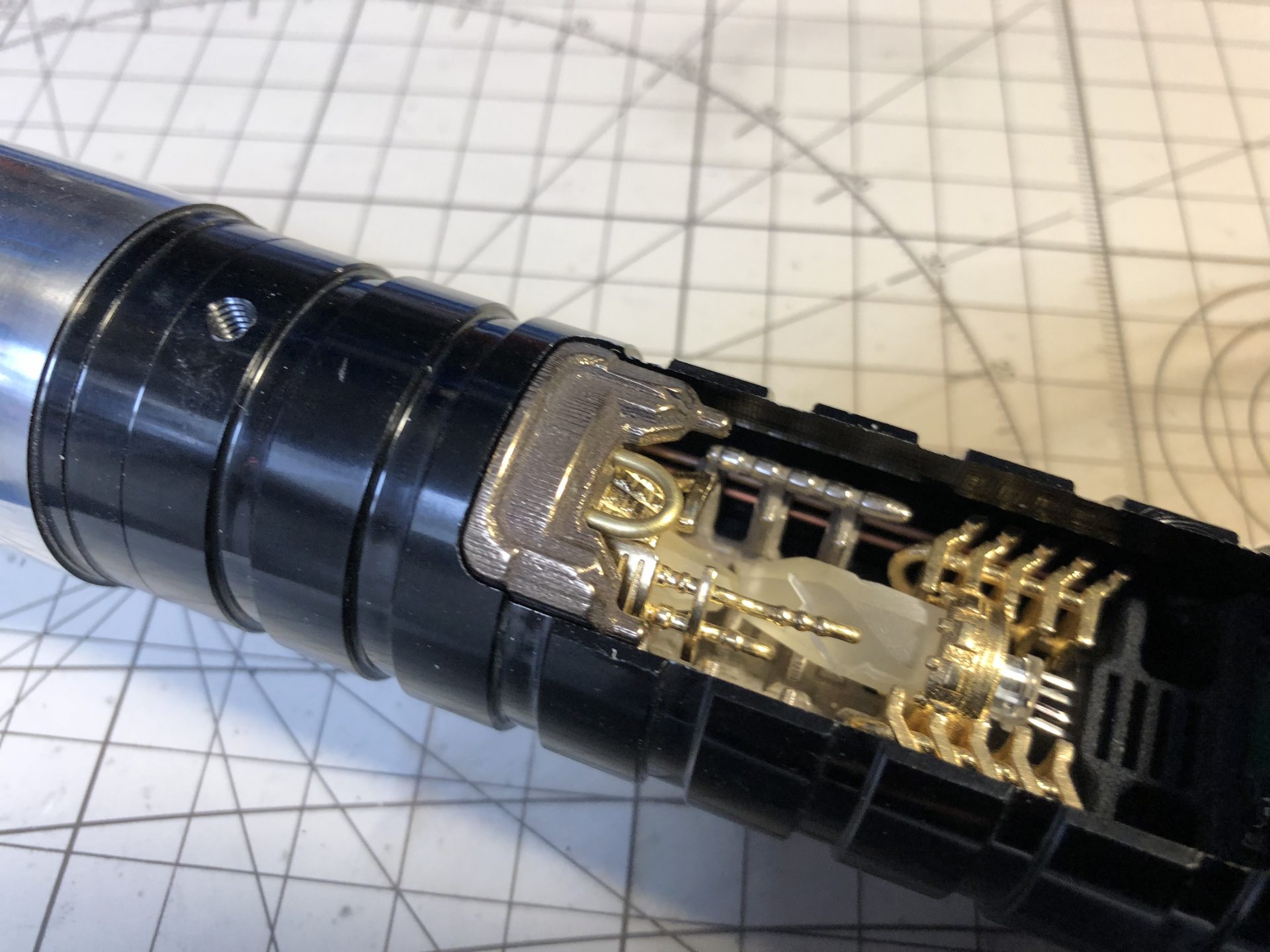
The Crystal Chamber caps can now be added, first Part 5, as follow. The U shaped 1.5mmOD rod can be slightly glued if necessary.
Part 3 is a removable cap, that locks with the chassis, to access the SD card when removed. A 1.5mmOD rod is necessary to act as handle (install the handle before locking the part with the chassis).
Finally the led module can be wired and locked using the delivered retention screw.
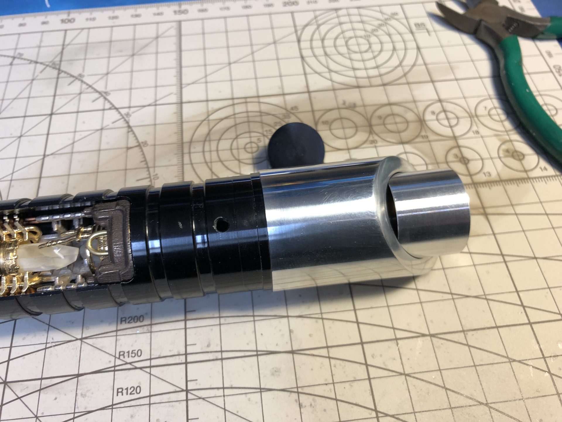
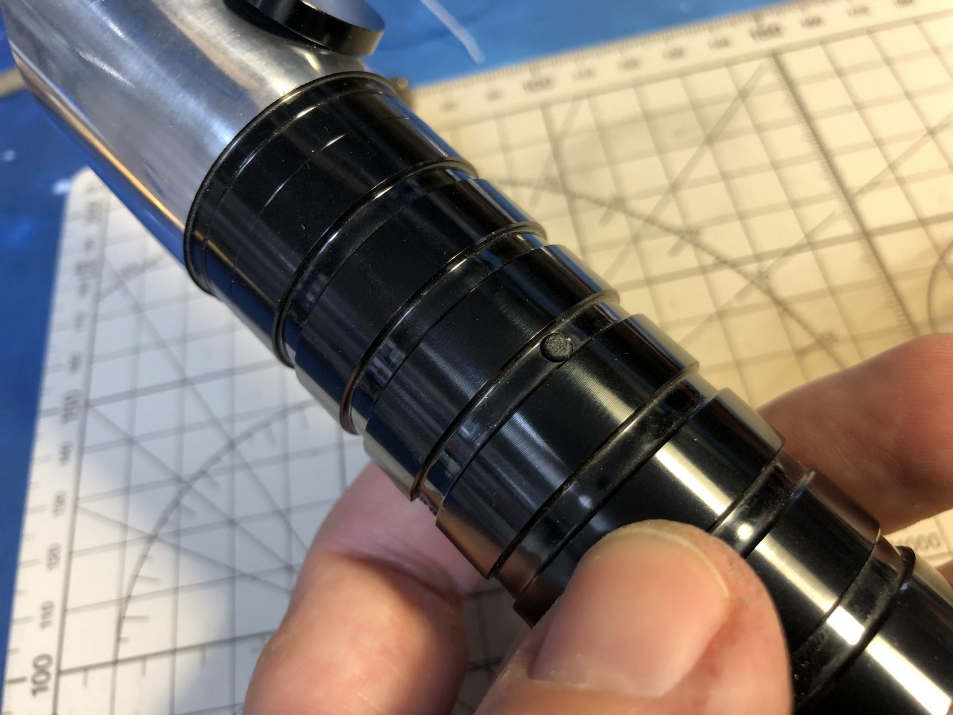
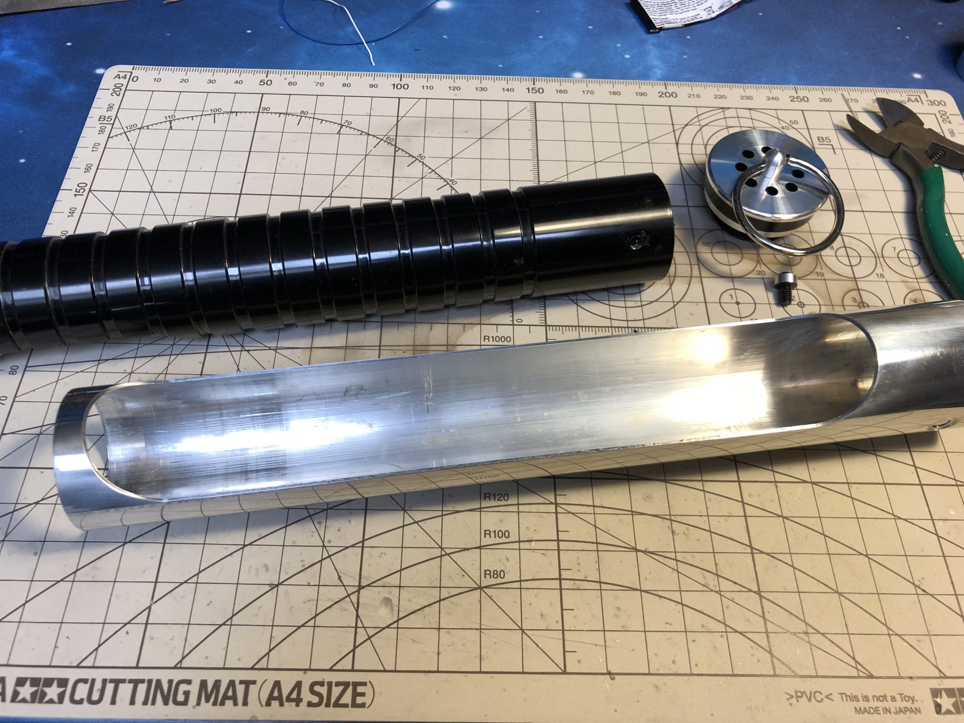
Once done, assemble back the shroud and pommel.
Important: the thumb screw that locks the shroud also locks the chassis in the hilt.
– Leave the pommel on when revealing the crystal chamber (by twisting the shroud)
– Leave the thumb screw on when unscrewing the pommel to access the kill switch / recharge port.