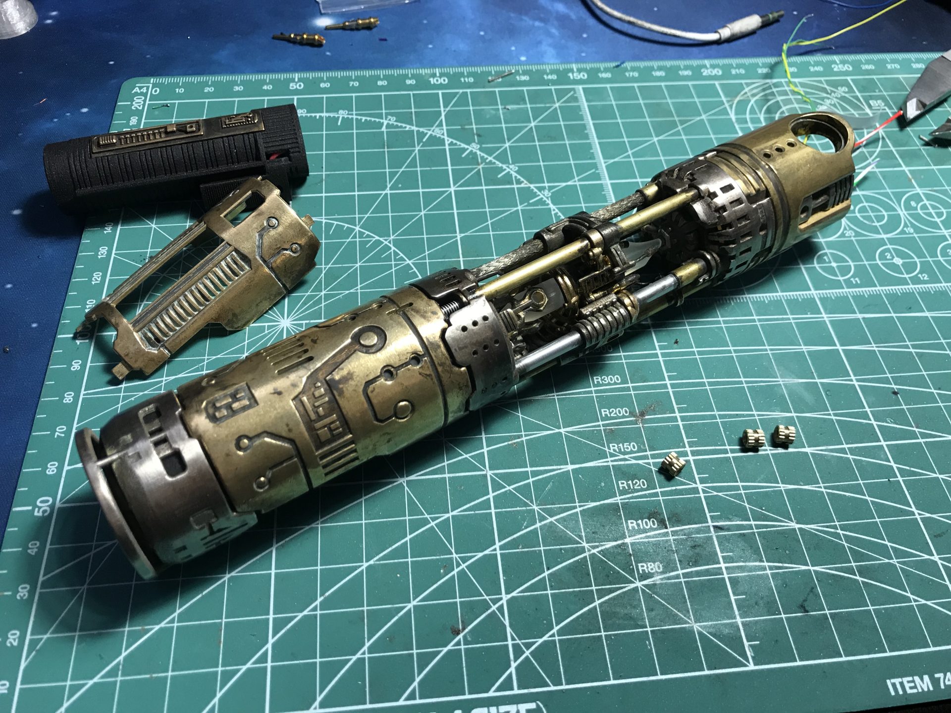
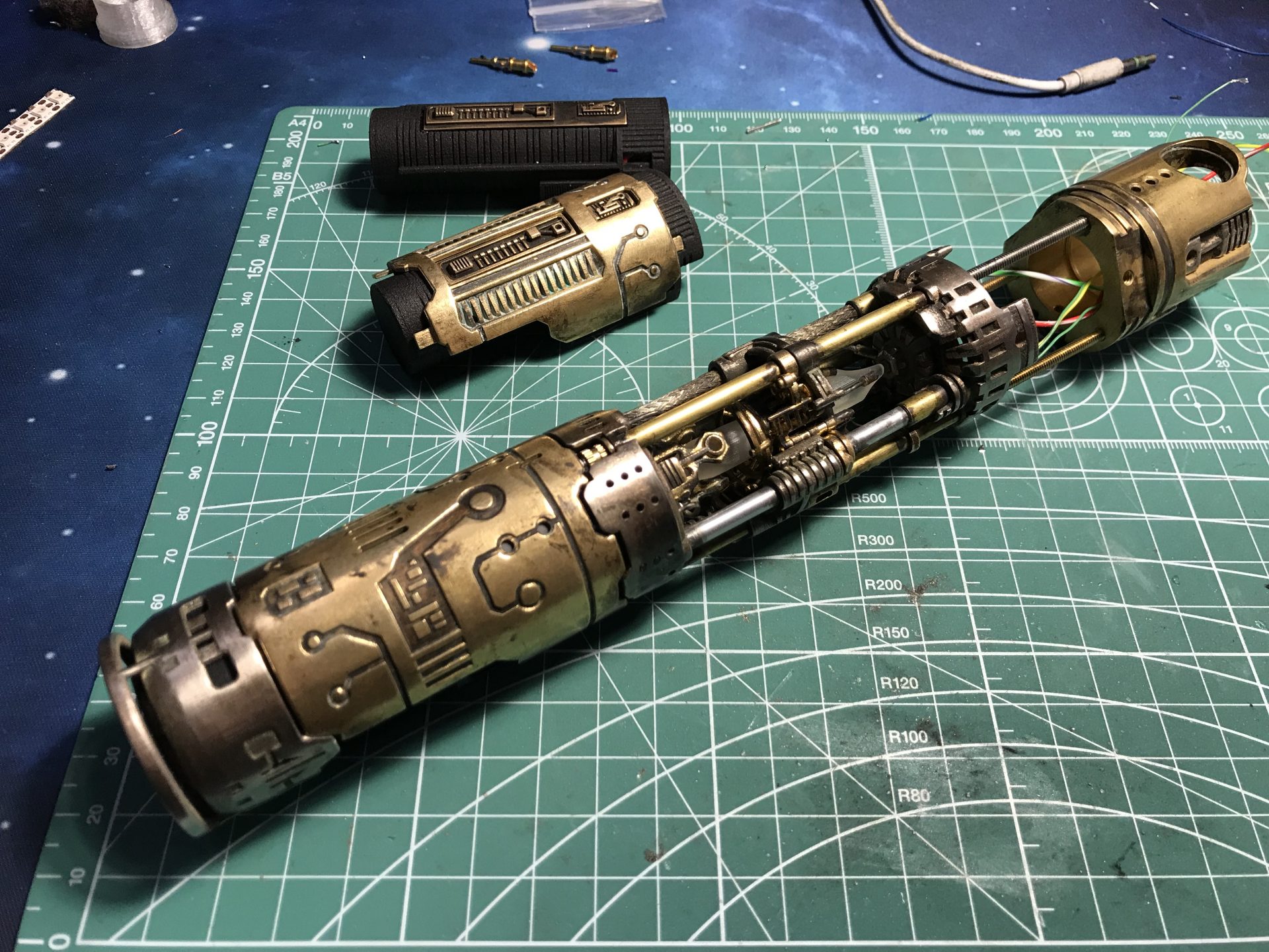
Graflex Mentor Chassis Var2

Components Details:
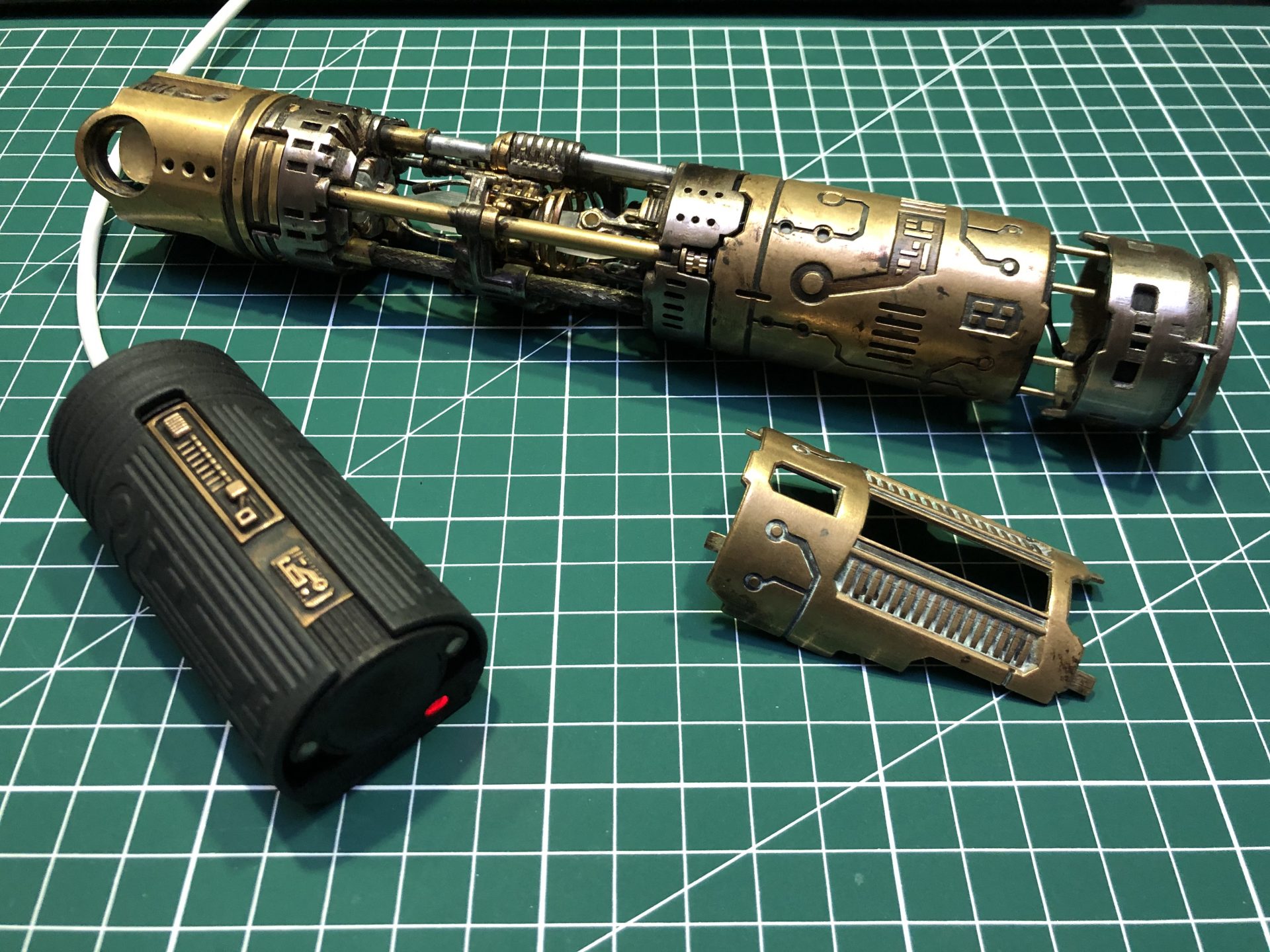
While retaining the overall design aspect, this chassis is mainly meant for Neopixel installs.
The main feature of this variant 2 is the usage of 18650 batteries, with removable capability.
It doesn’t have the Rotating Chamber features but is easier to install.


The following parts will depend on the Blade Holder used – NWL Master Blade Holder is recommended for this chassis for the best reveal appearance.
(Recommended materials are mentioned in brackets):
– NWL Master:
⇒ Part1 – Style2 (Steel or Brass/Bronze): Blade-Generator-style2
——— or Style4 (for Extend-X Neopixel connector – Black Plastic): WIP
⇒ Switches Cover (Steel or Brass/Bronze): NWL_Master_Switches-Cover
⇒ BH Greeblies (Steel or Brass/Bronze): Blade-Holder-Greeblies
– NWL Deluxe V2:
⇒ Part1 – Style1 (Steel or Brass/Bronze): Blade-Generator-style1
——— or Style3 (for Extend-X Neopixel connector – Black Plastic): WIP
⇒ Switches Cover (Black Plastic or Black Steel): NWL_Deluxe_V1_Switches-Cover
– NWL Deluxe V1:
⇒ Part1 – Style1 (Steel or Brass/Bronze): Blade-Generator-style1
——— or Style3 (for Extend-X Neopixel connector – Black Plastic): WIP
⇒ Switches Cover (Black Plastic): NWL_Deluxe_V1_witches-Cover
– KR-Sabers, TGS, Roman (others):
⇒ Part1 – Style1 (Steel or Brass/Bronze): Blade-Generator-style1
——— or Style3 (for Extend-X Neopixel connector – Black Plastic): WIP
The rest of the chassis is common:
⇒ Part 02: Arc-Reactor-1 (Steel or Brass/Bronze)
⇒ Part 03: Arc-reactor-2 (Smoothest Plastic)
⇒ Part 04: Power-Gate (Steel or Brass/Bronze)
⇒ Part 05: Crystal-Chamber (Brass/Bronze)
⇒ Part 06: Crystal-Generator-style1 (Brass/Bronze)
⇒ Part 07: Crystals(Smoothest Plastic or Quartz stones)
⇒ Part 08: Generator-Gate-1 (Steel or Brass/Bronze)
⇒ Part 09 – Style1: Power-Module (For CFX + 28mm bass – Black Plastic)
——— or Style2: Power-Module (For MultiBoard + 28mm bass – Black Plastic)
⇒ Part 10: Power-Cell (Black Plastic)
⇒ Part 11: Power-Cell-Cover (Brass/Bronze)
/!\ Buy several Part10 and Part11 to build more battery packs and be able to switch batteries.
⇒ Part 12: Power-Switch (Brass/Bronze)
⇒ Part 13: Cover-Plate-1 (Brass/Bronze)
⇒ Part 14: Cover-Plate-2 (Brass/Bronze)
⇒ Part 15: Generator-Gate-2 (For 28mm bass speaker – Steel or Brass/Bronze)
⇒ USB Power Cell Charger – Charger
(electronic parts for the USB charge available free on demand trough contact page)
Old parts:
⇒ Part 09: Power-module (MultiBoards + 28mm flat speaker – Black Plastic)
⇒ Part 15: Generator-Gate-2_old (For 28mm flat speaker – Steel or Brass/Bronze)
Other Parts:
Here is a list of parts needed to install the Variant2 Chassis
⇒ 4-40 threaded rods x 3 (recommended in brass)
⇒ 4mm long 4-40 nuts: x 3 (example, other type of nuts can be used)
⇒ Bulgin Brass Pins (high amp): Female and Male pins
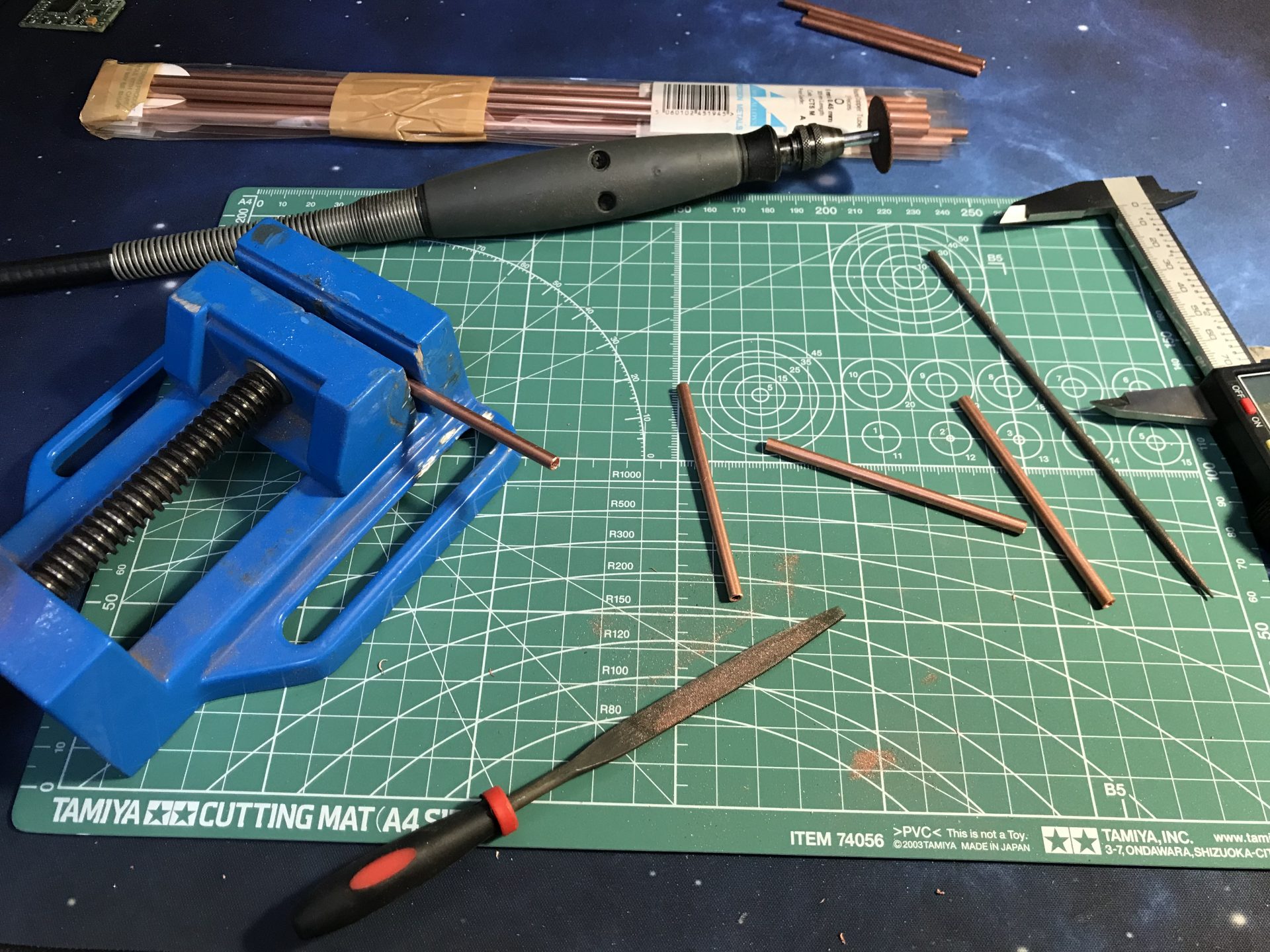
⇒ Brass, Aluminium or Copper tube: 4mmOD (1x76mm, 3x75mm, 2x28mm), 5mmOD (2x10mm)
⇒ Brass, Aluminium or Copper rods: 1mmOD (1x14mm), 1.5mmOD (2 rods to be shaped in U).
⇒ Optional tubes and rods: You can add an additional mix of rods and tubes to the chassis Part01 and to the Crystal Chamber Part07.
⇒ Magnets: 8 x 3mmx2mm magnets
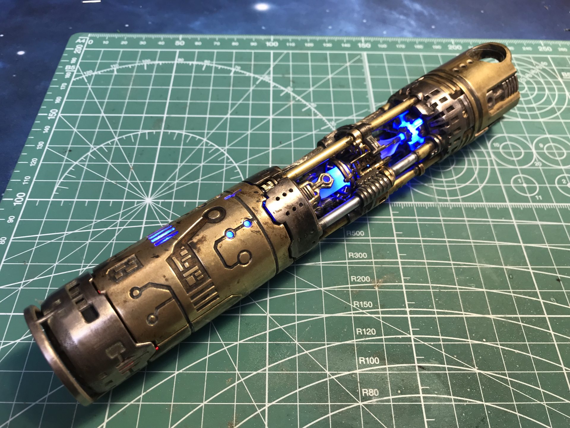
Demo:
DIY Instructions:
Disclainer:
– These instructions will details the install procedure as much as possible. GOTH-3Designs cannot be held responsible for any mistakes made by DIYers.
– Always wear protective gear when working on install (gloves, eye protection, …), GOTH-3Designs cannot be held responsible in case of accident.
Note 1: These instructions will cover the ProffieBoard install, however we do not cover wiring instructions tho, please read your soundboard manual before starting the install. Other soundboard install procedure is similar.
Note 3: The install can be done with any of blade holder available. These instructions are done with NerfworXlab’s Master Blade Holder.
Note 4: This kind of chassis isn’t meant for dueling. Display or Cosplay only.
Note 5: Check the Variant 1 chassis for more details on Vintage Graflex Flashgun conversion.
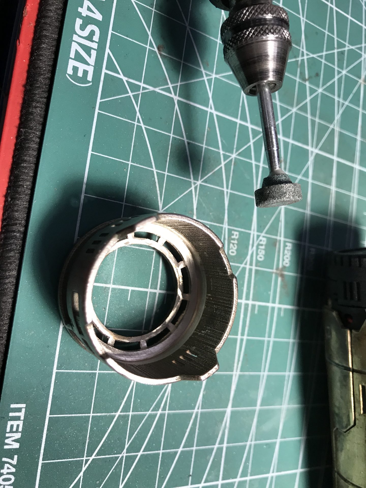
Note 6: When using steel material, it can be optionally sanded until obtaining a smooth surface. Here is an example using the same “Polished Bronze Steel material”, sanded on the left and raw on the right.

MULTIBOARDS ADAPTIVE CHASSIS (Part9 Style1)

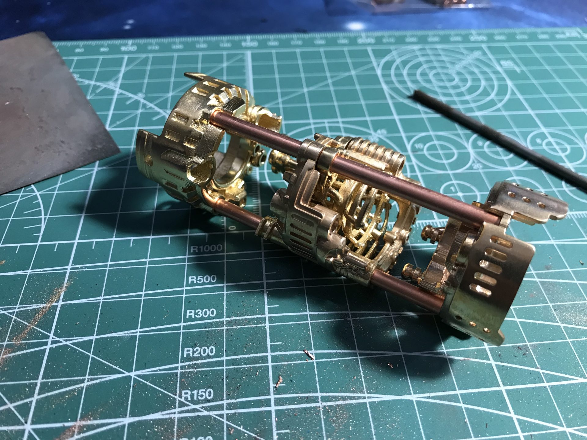
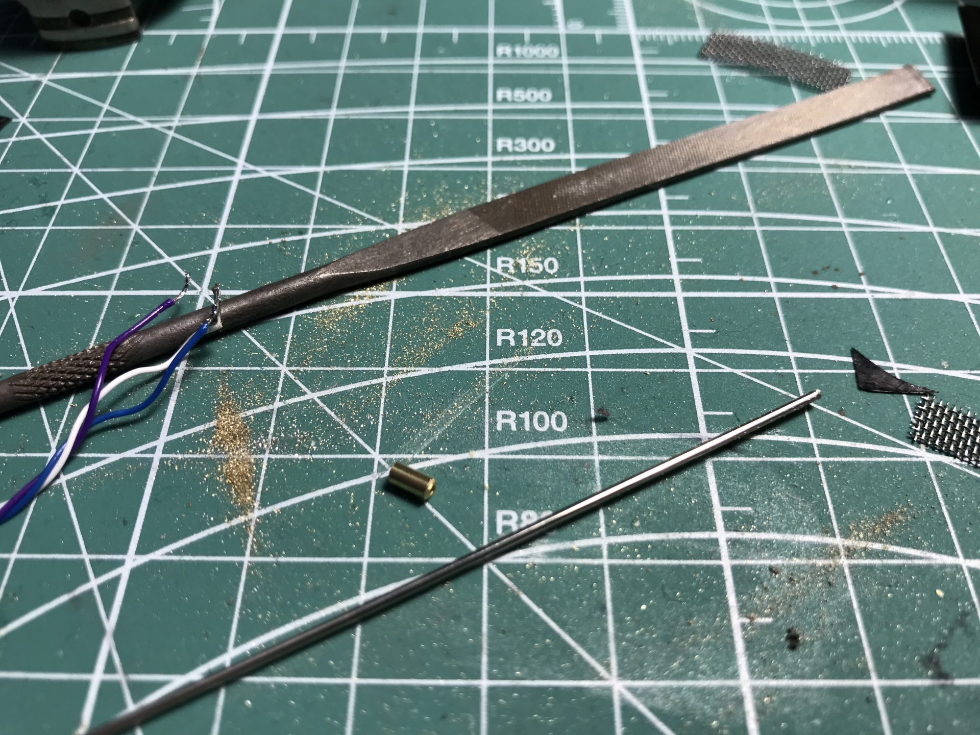
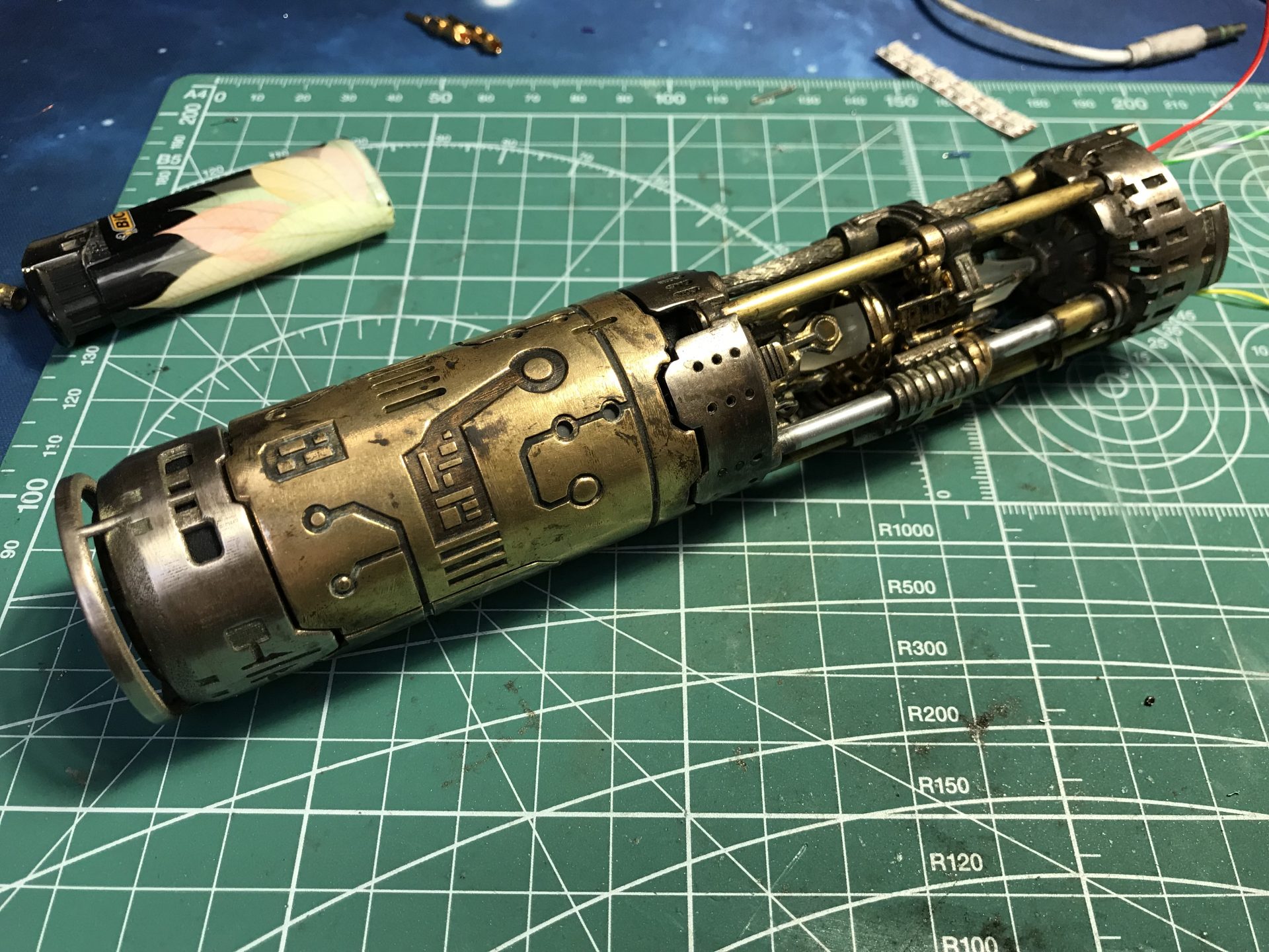
Step 1: Cut the rod and tubes, then test fit the parts (some sanding and holes cleaning could be required if using steel parts for example).

4mmOD = (1) – 3x75mm,(2) – 1x76mm, (3) – 2x28mm,
5mmOD = (4) – 2x10mm
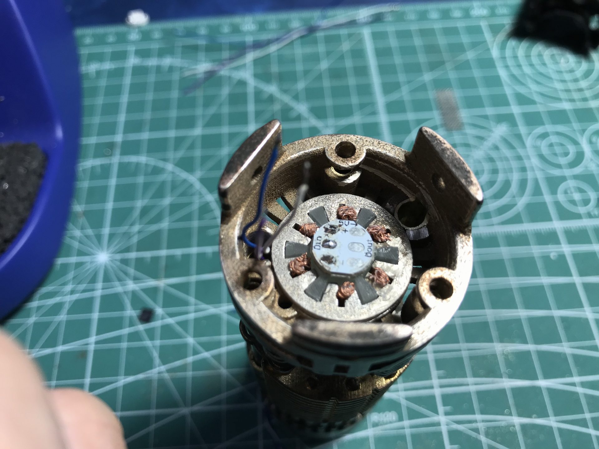
Step 2: Prepare the Arc Reactor, using copper stranded wires (salvaged for electric cables for example).
Check the video below from the Mentor Var1 for the detailed assembly (install on this Var2 is similar).
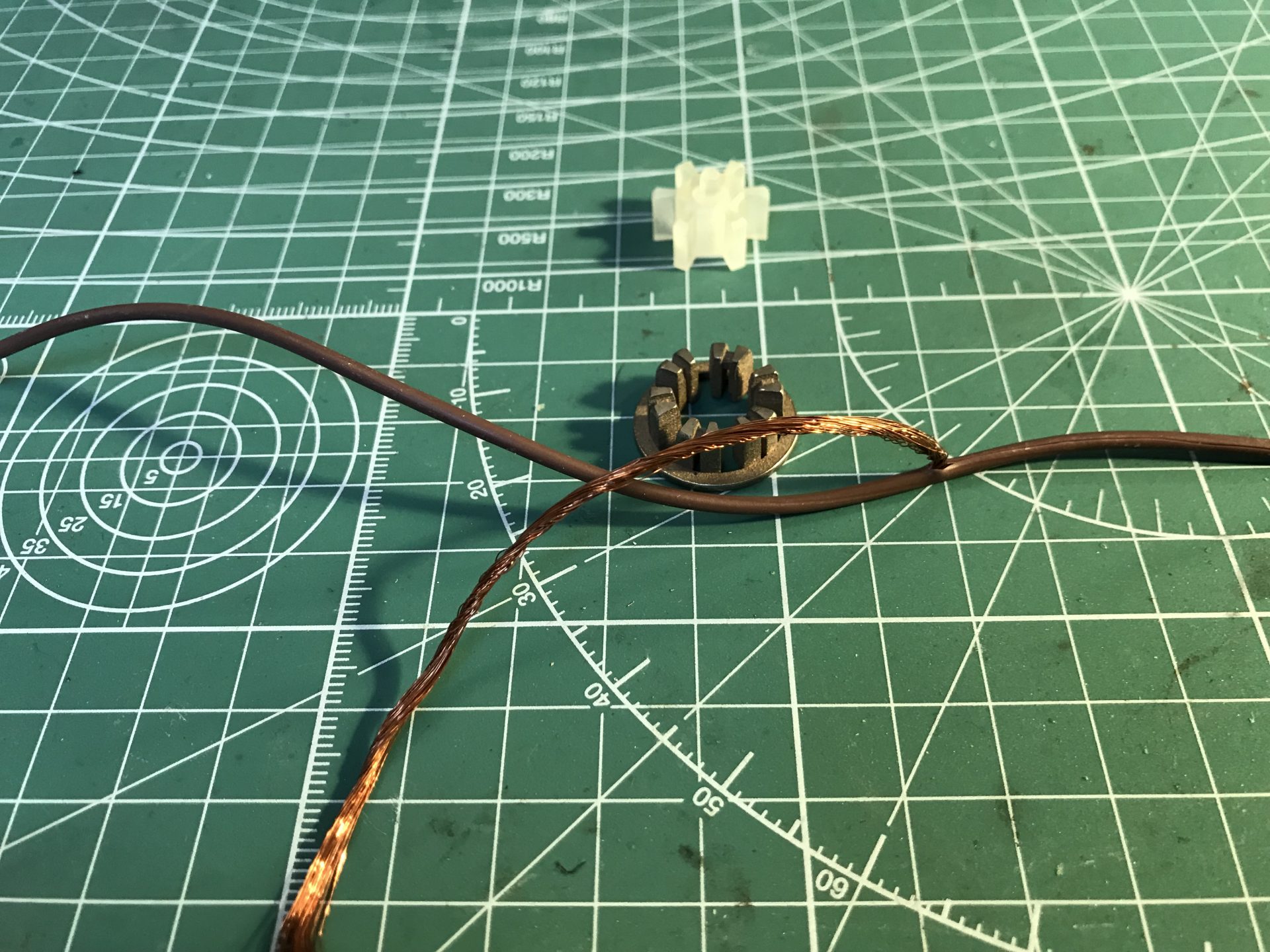
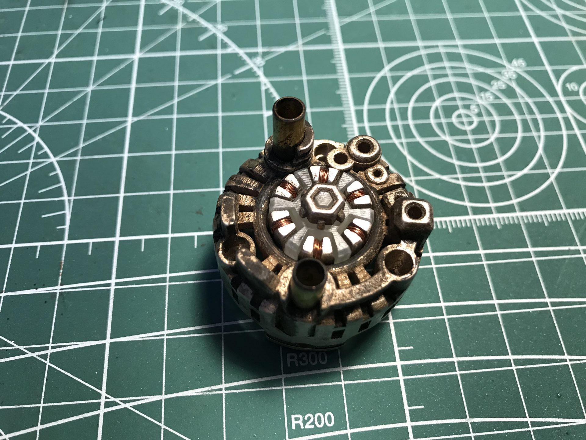
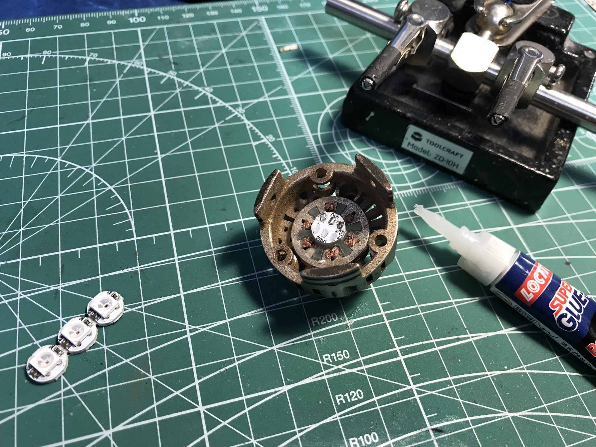
For Neopixel install, using a single pixel on PCB is recommended. The 5mm accent led hole can then be drilled a bit to accomodate the pixel (super glue is used to secure it).
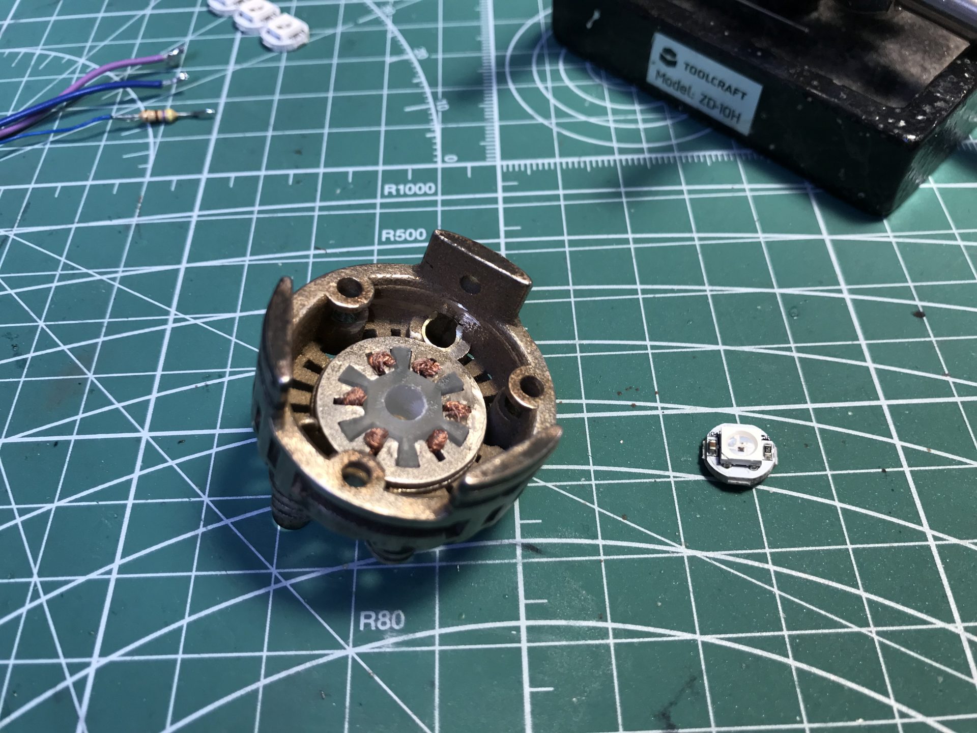
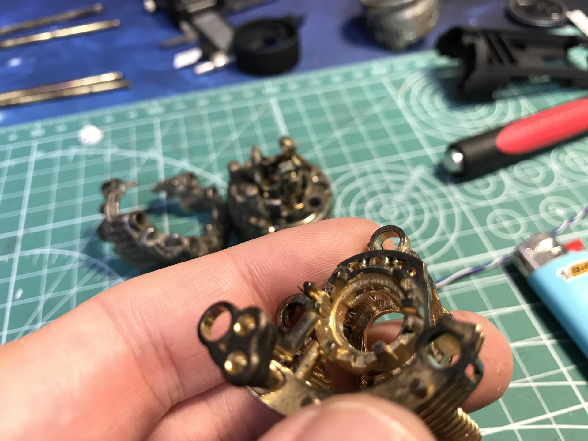
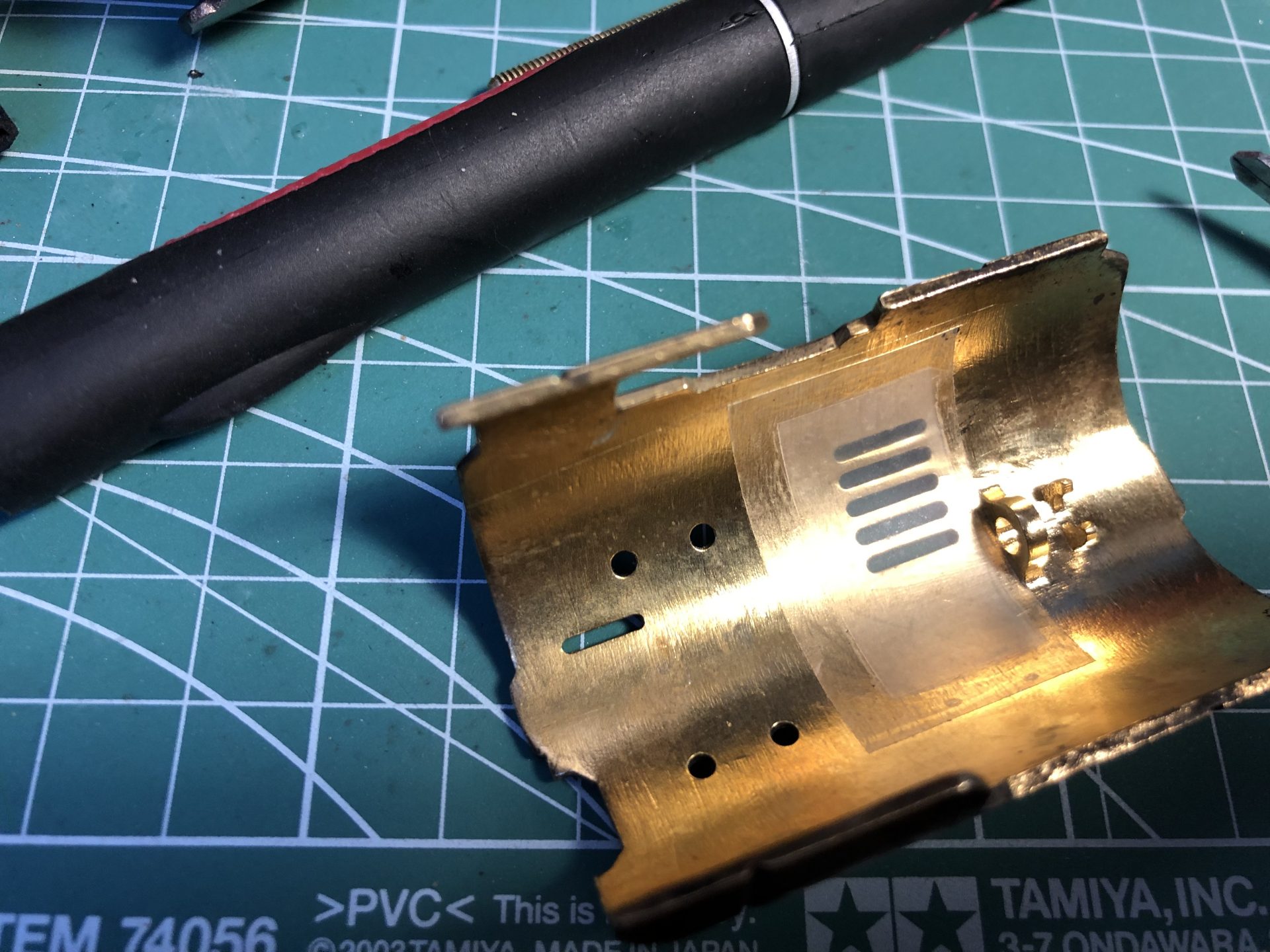
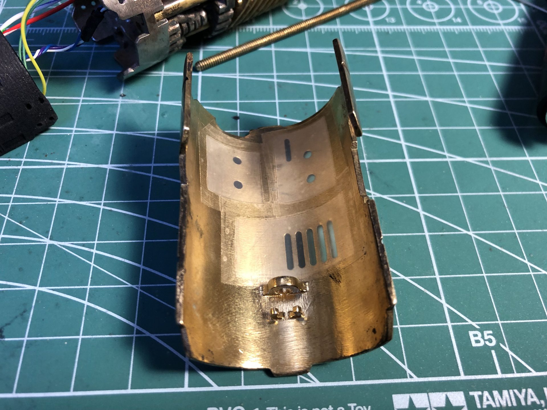
Step 3: The crystal chamber is planned for two 5mm accent led back to back (as shown in the Mentor Var1 instructions step 19). However, for Neopixel install, 2 pixels on PCB can be used as shown below.
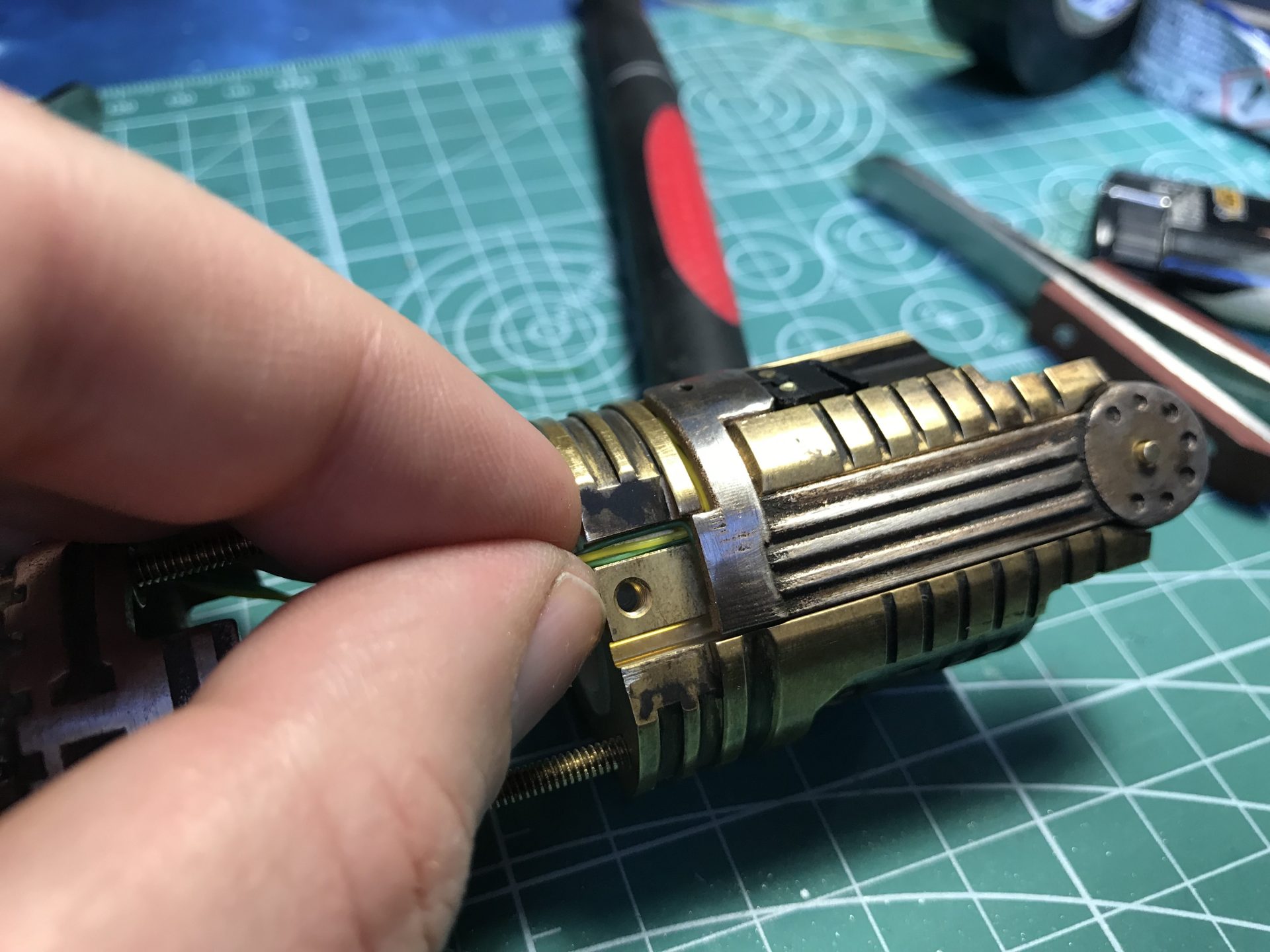
In order to ease the install, expand the hole shown in this picture (do not fully remove the crystal support thought).
Then wire the pixel as shown below (making sure to respect the arrow direction).

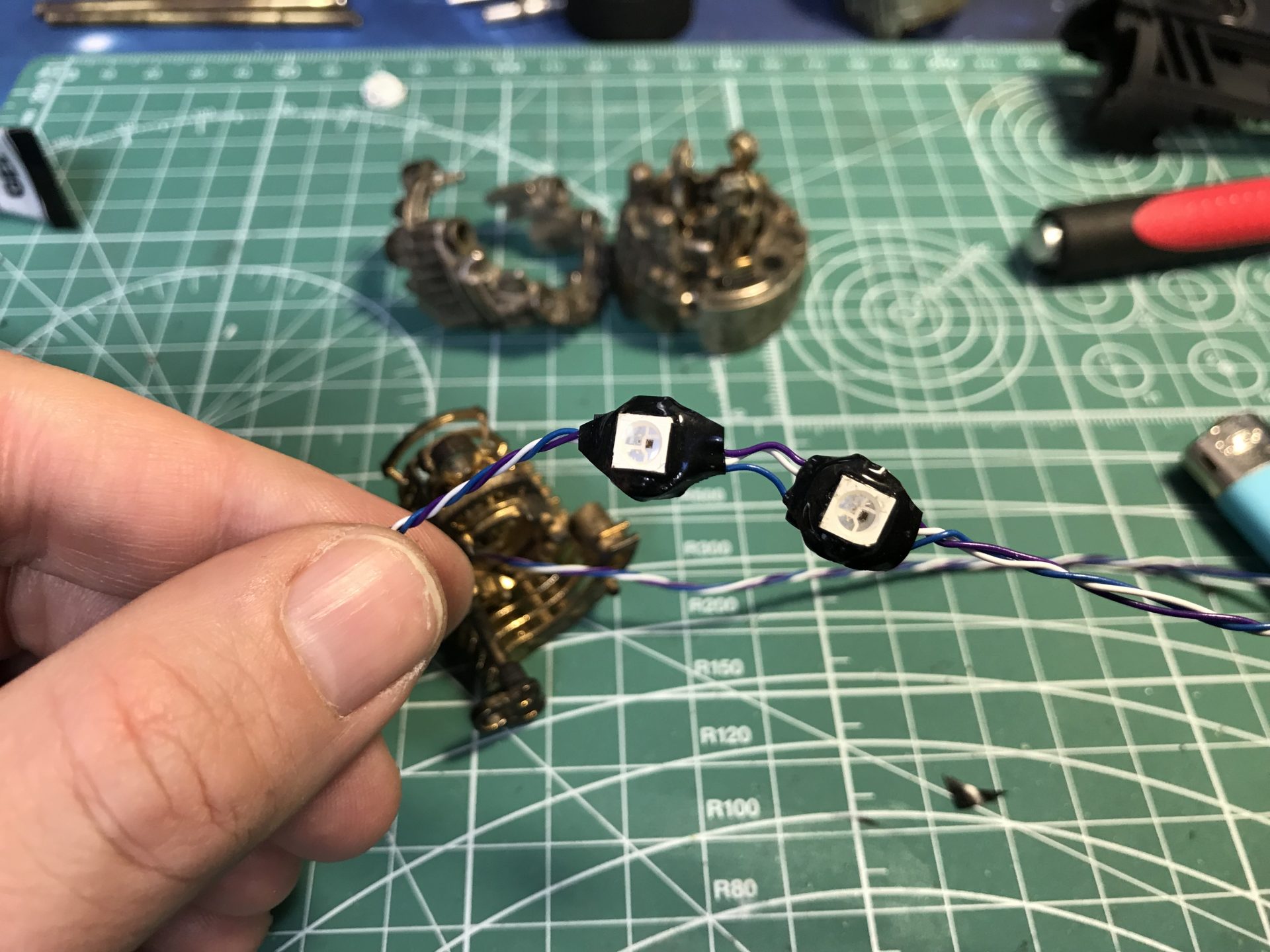
Insert the wires and next the first pixel facing the bottom of the chamber (first picture below), then insert the second pixel.
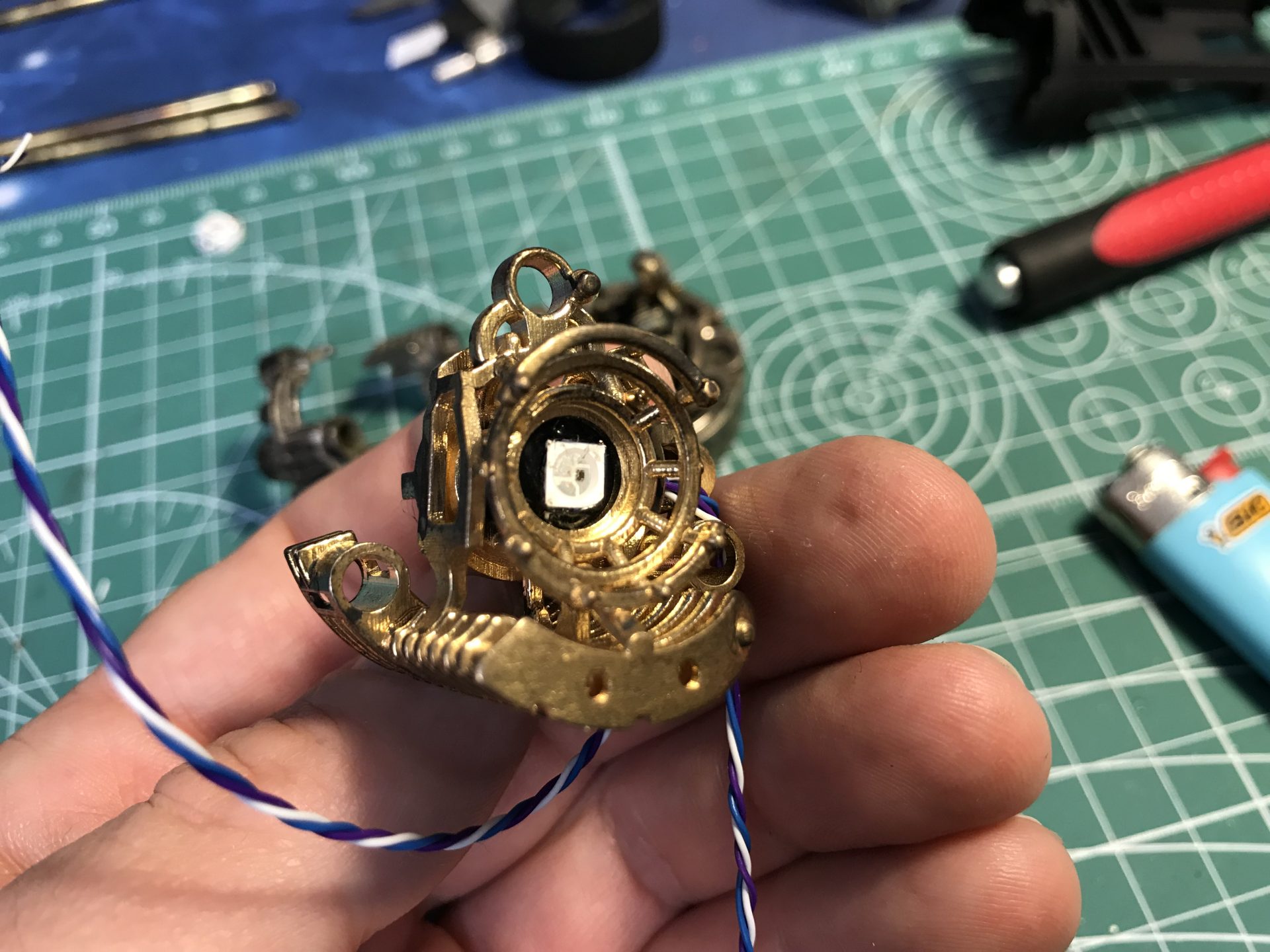

Some cosmetic elements can also be added to hide the wires.
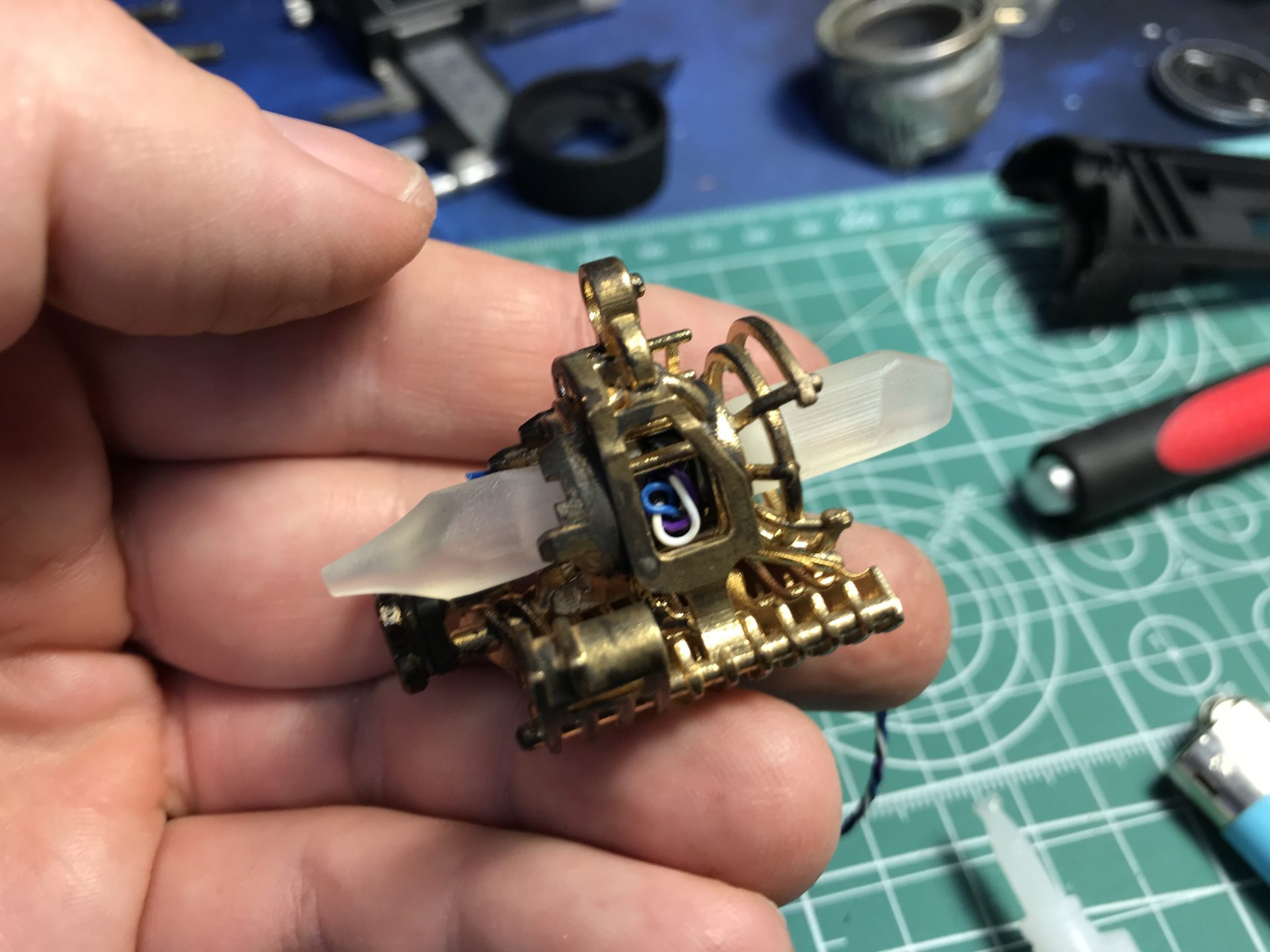
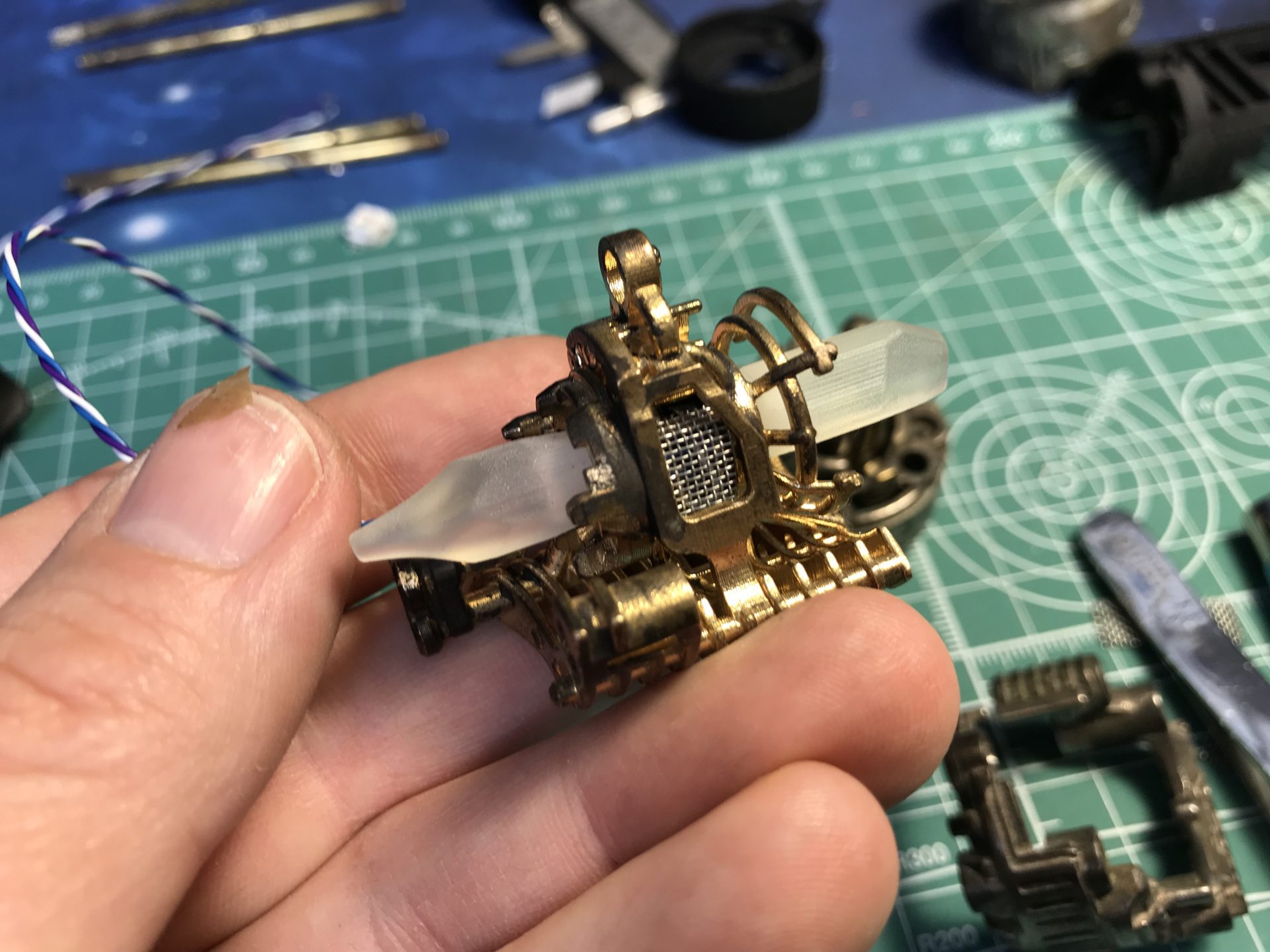
Step 5: Part 6 can then be added (before gluing the crystals in place to make it easier, unlike what these pictures show).
First pass the crystal wire in the dedicated hole, then join both parts, as shown in these pictures.
Once assembled, glue the crystals into their respective slot (the pointy crystal goes in front).
Step 6: Add the 1.5mmOD rod, which need to be shaped into a U, as shown below.
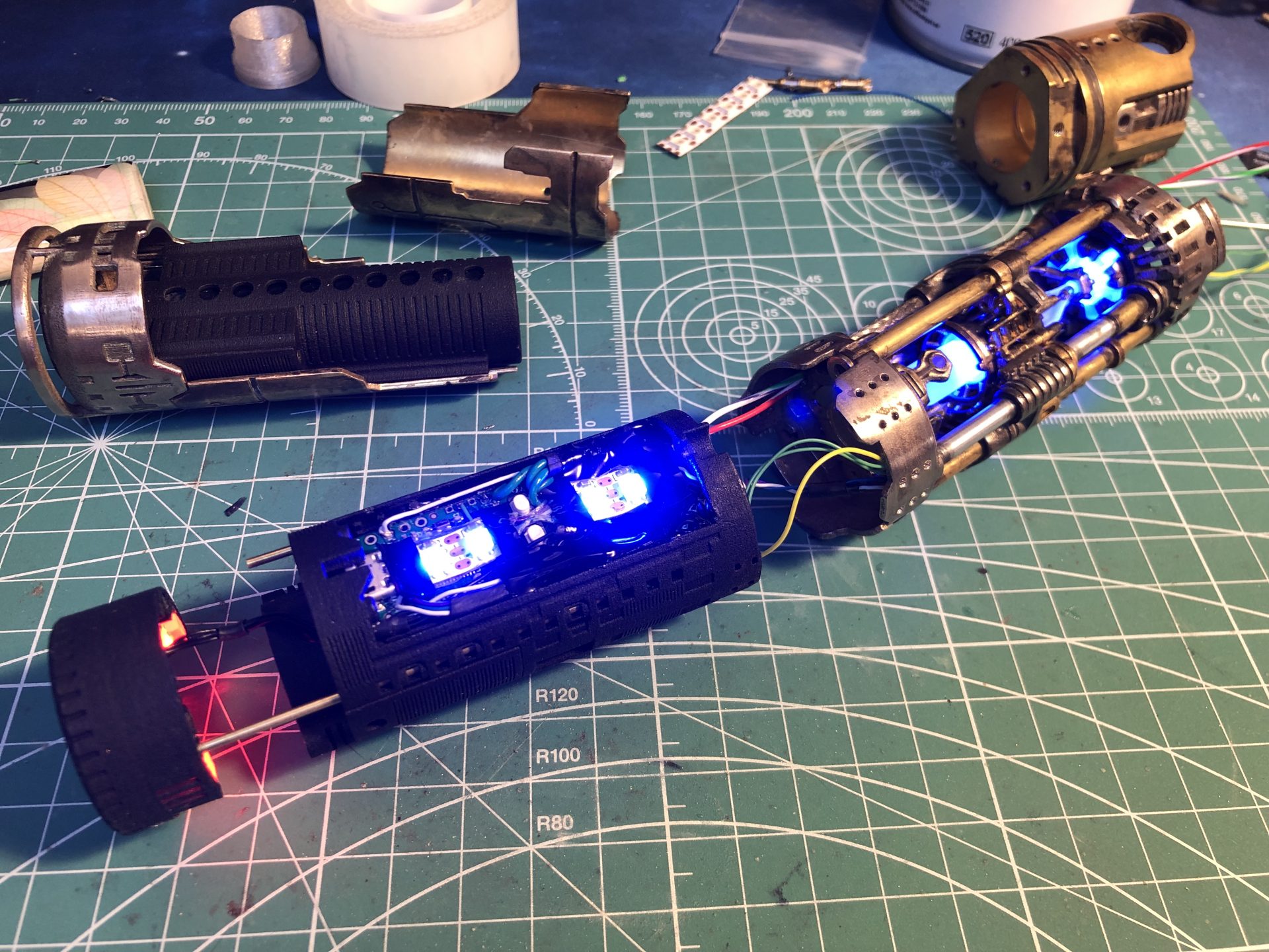
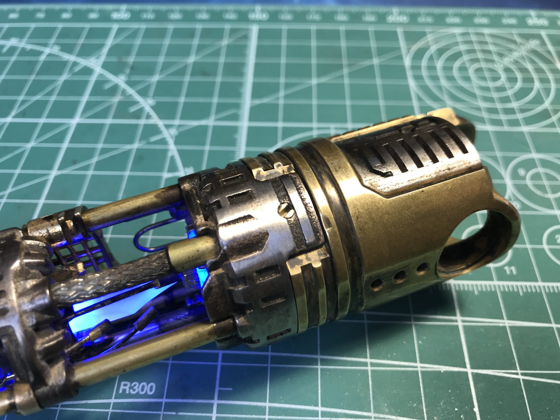
In this example test, we have linked the crystal chamber and Arc Reactor pixels as a dedicated blade.
Step 7: Add the cosmetic greeblies on the crystal chamber according to what you like (here is an example using 1mmOD rods and 2mmOD Tubes). Small rods and tubes can also be added on part 1 around the Arc Reactor.

Step 8: Assemble the Crystal Chamber back together, and wire the Arc Reactor led.
Step 9: Add the main led or neopixel connector and switches wires into the channel, making sure they can move easily back and forth.
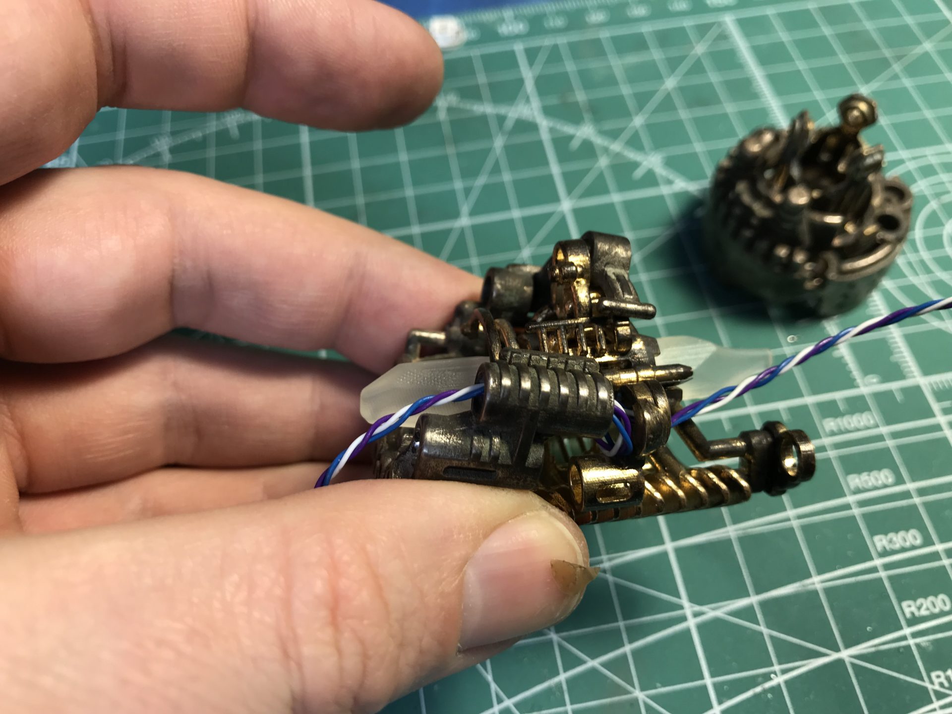
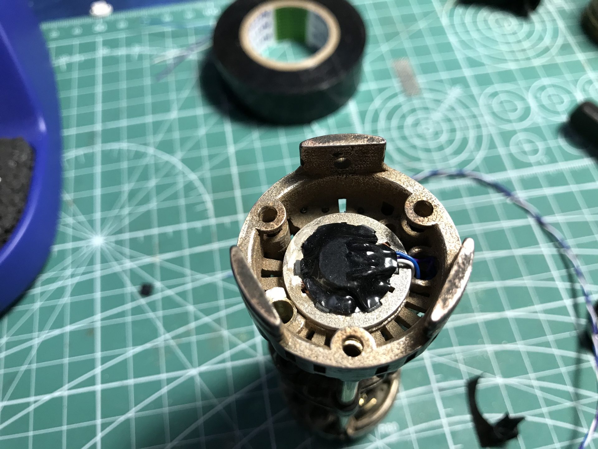
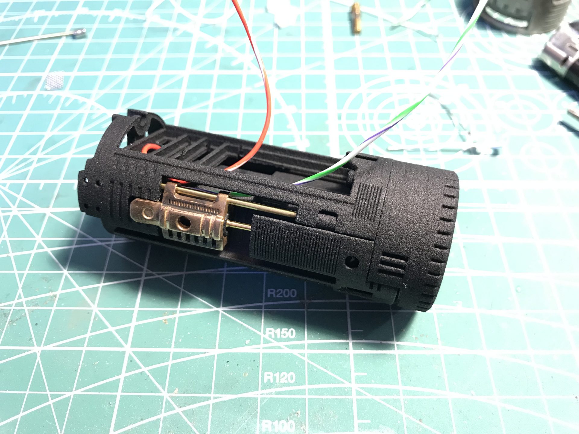
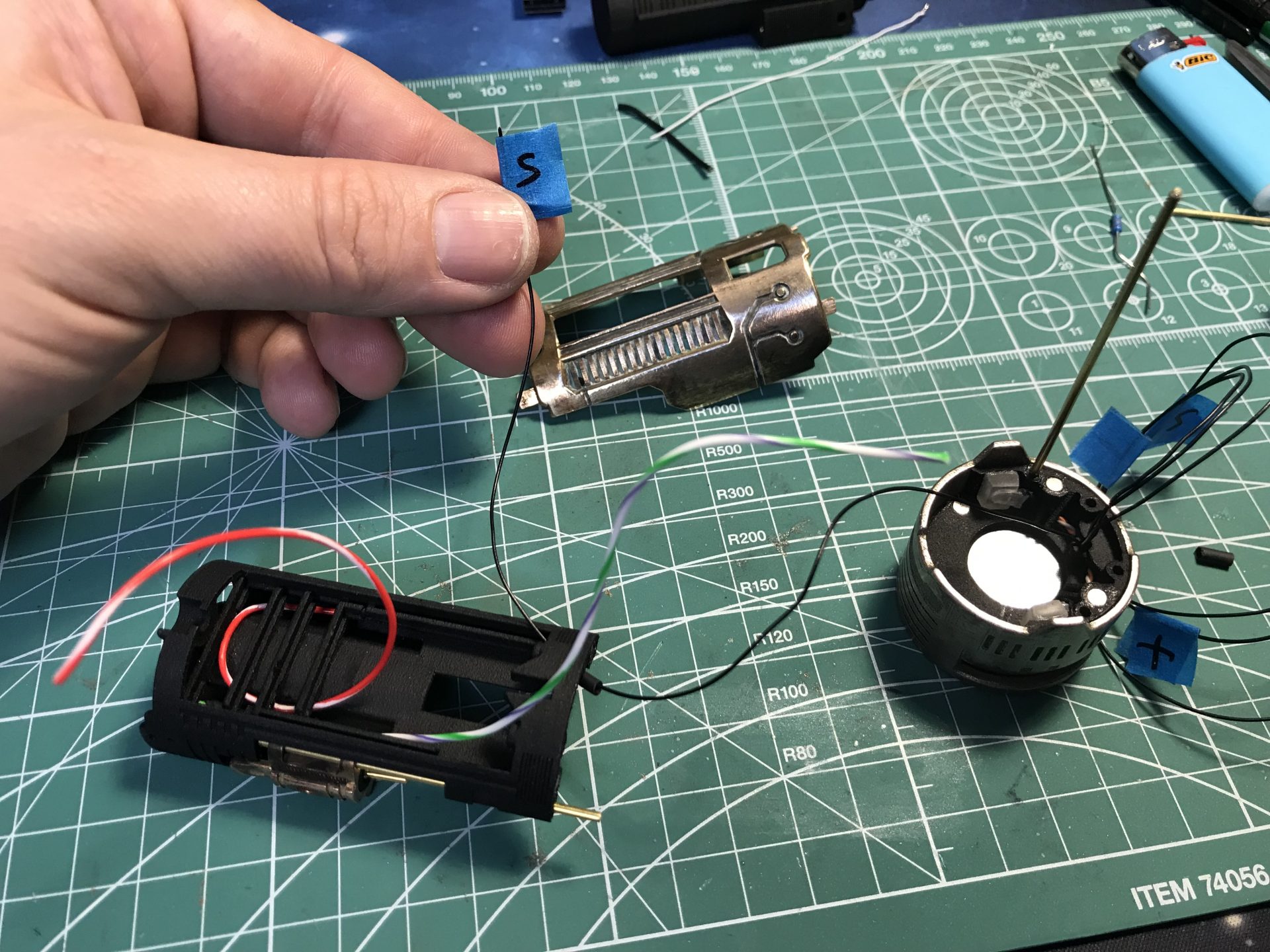
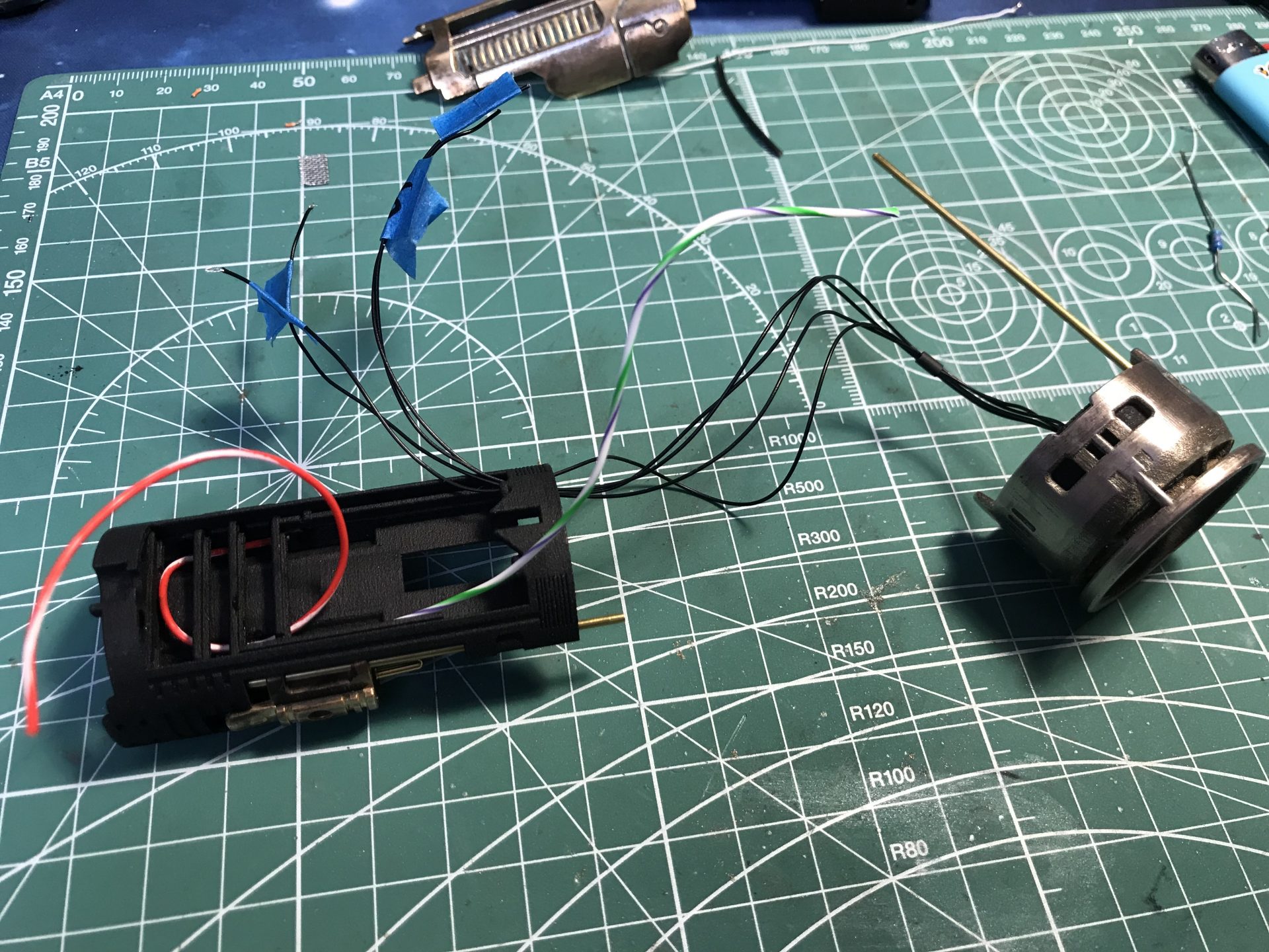
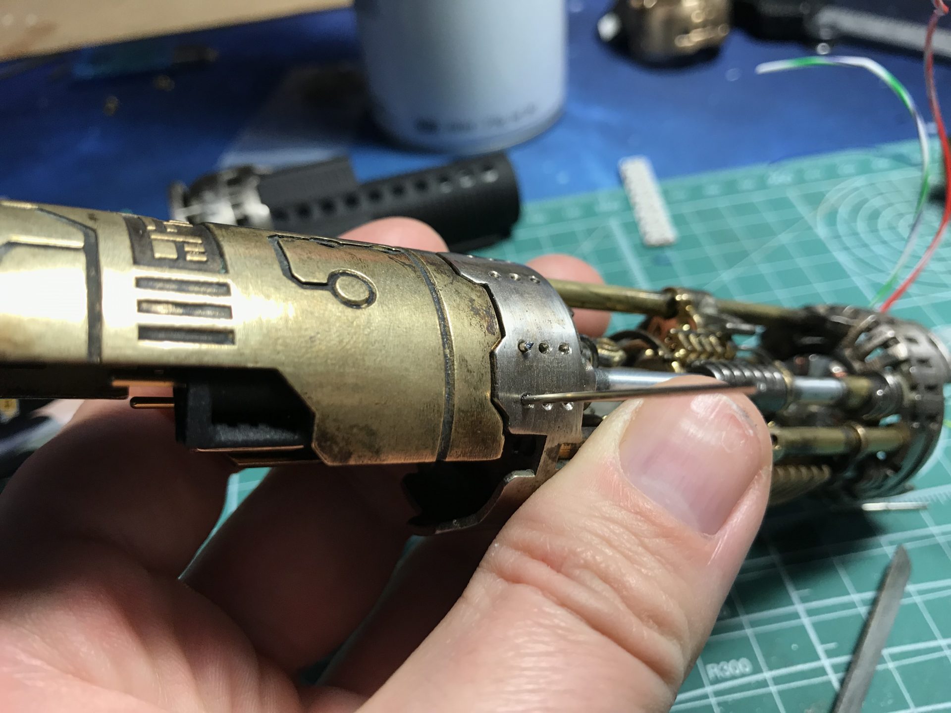
Step 10: Brass pins install. Cut apart the 3 pieces of part 11 (carefully using an exacto knife).
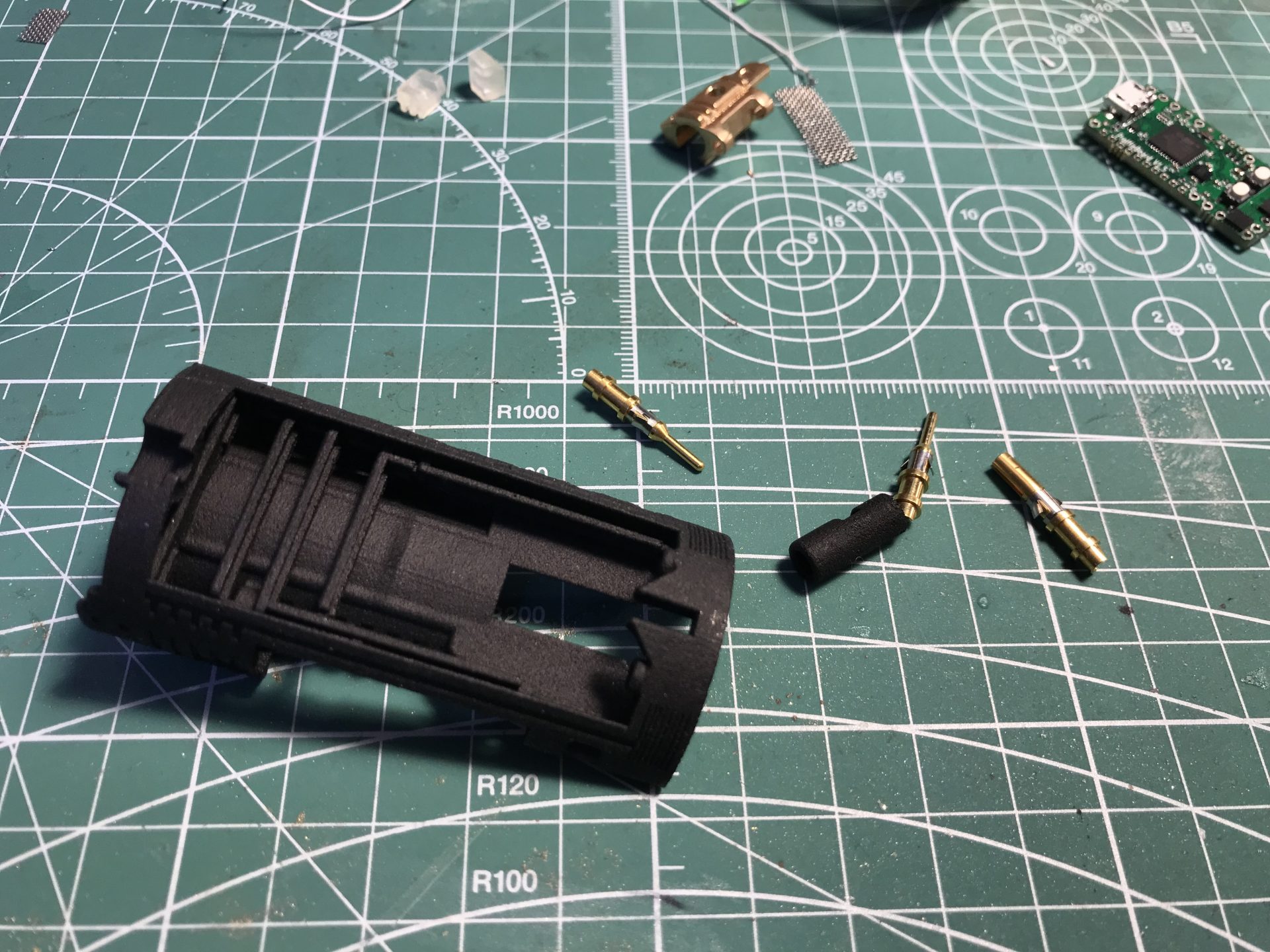
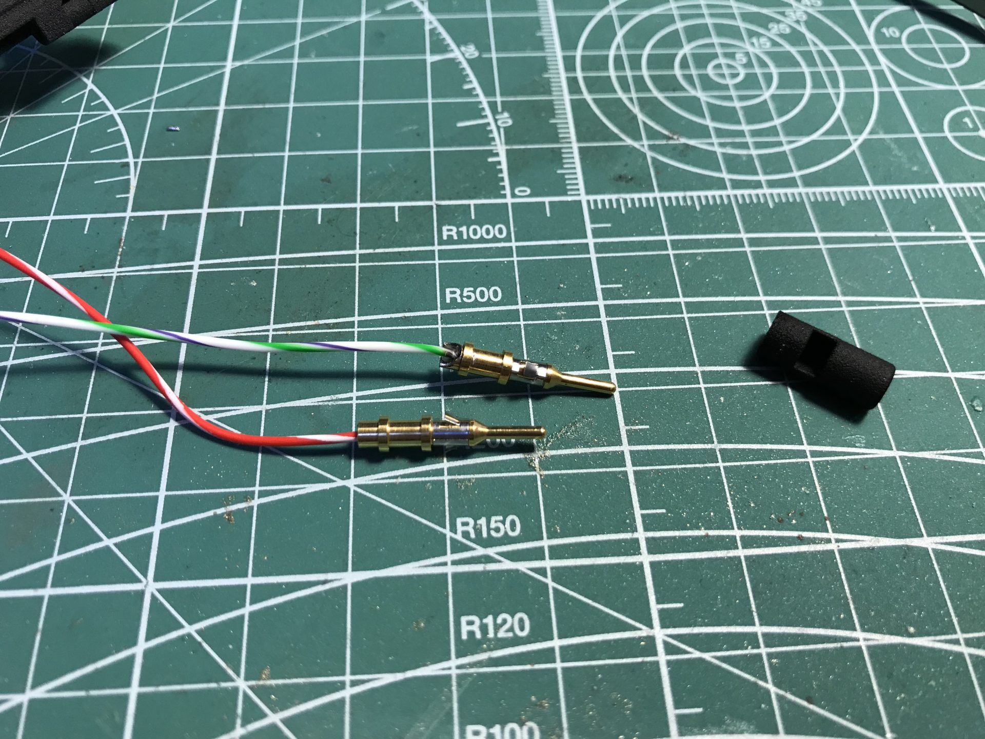
Wire the brass pins with pos and neg wires. The neg pin is then added to the little housing (insulation). It will serve as on/off switch.
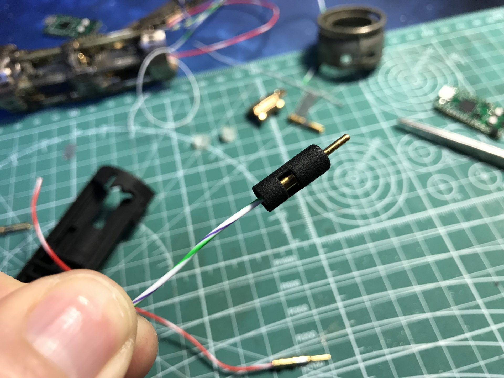
The pin and insulator is to be glued into part 12, and then added to the chassis as follow (the wire bend and passes through a hole int he chassis)
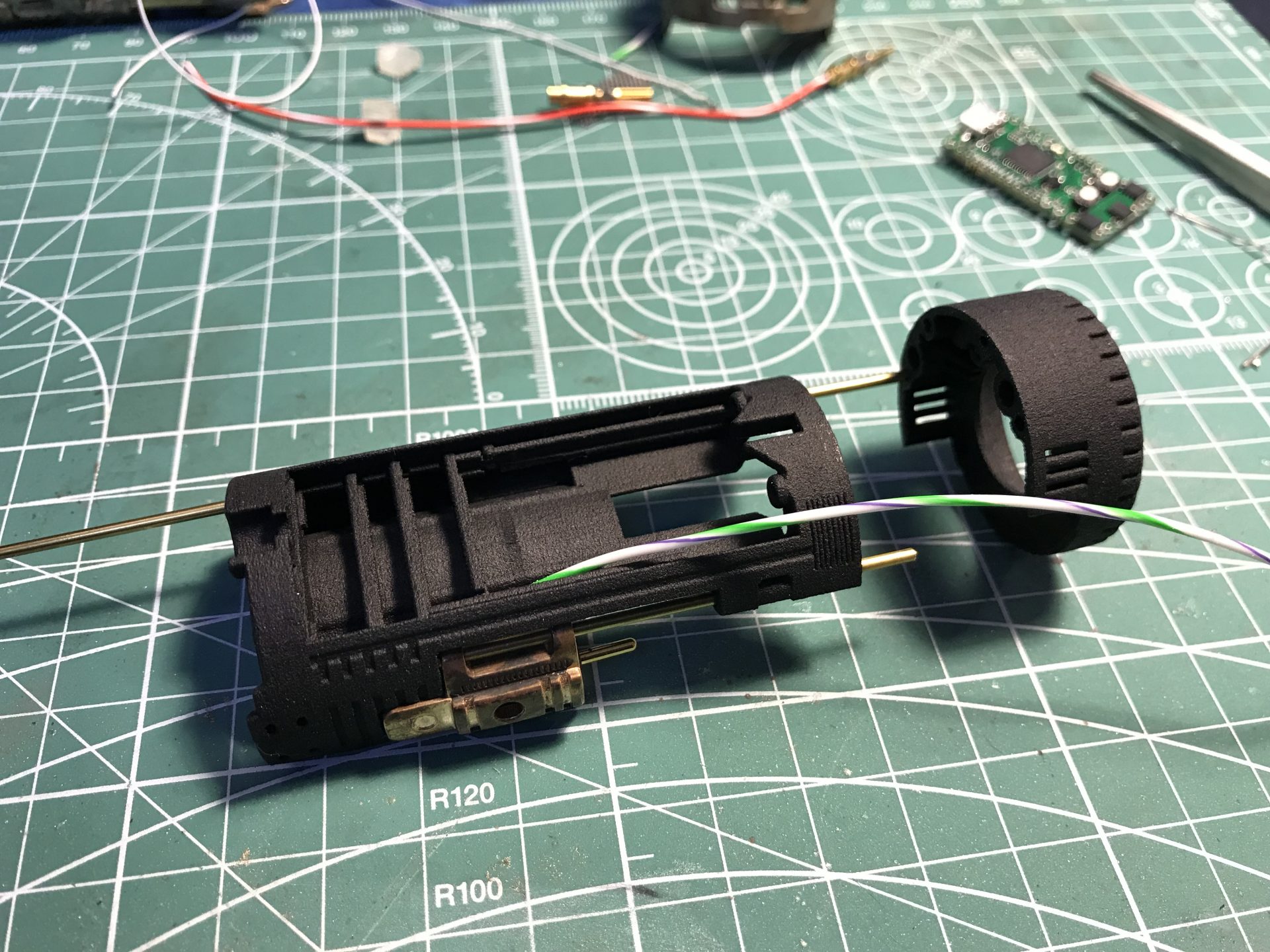
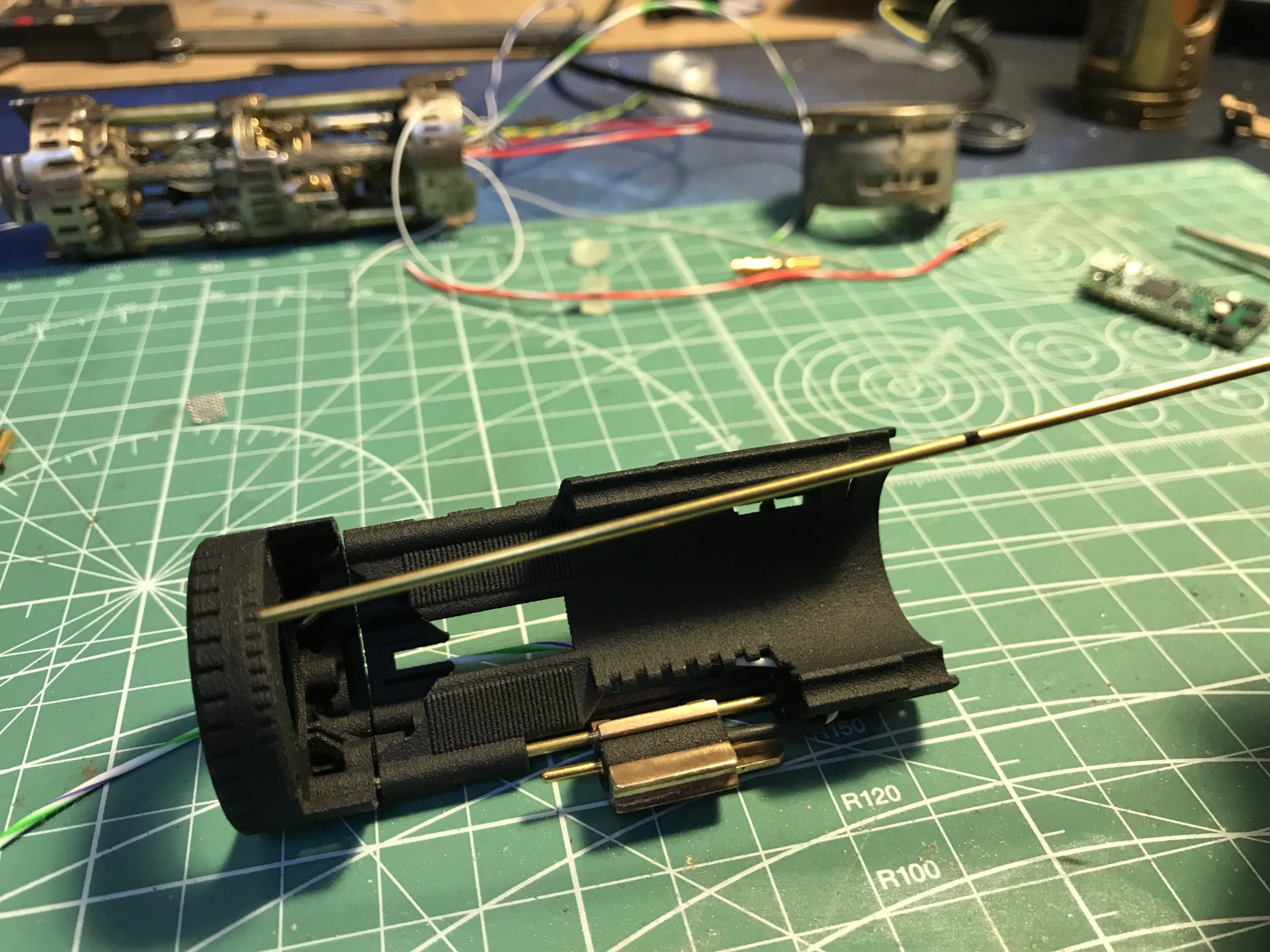
Step 11: Support 1.5mmOD rods install.
The first rod is static (glued on the chassis) and will serve as guide for the on/off switch assembly. Use the speaker holder to mark the right length where the rod needs to be cut.
The second rod support the speaker holder (glued on the speaker holder) which is used again to mark the right length.
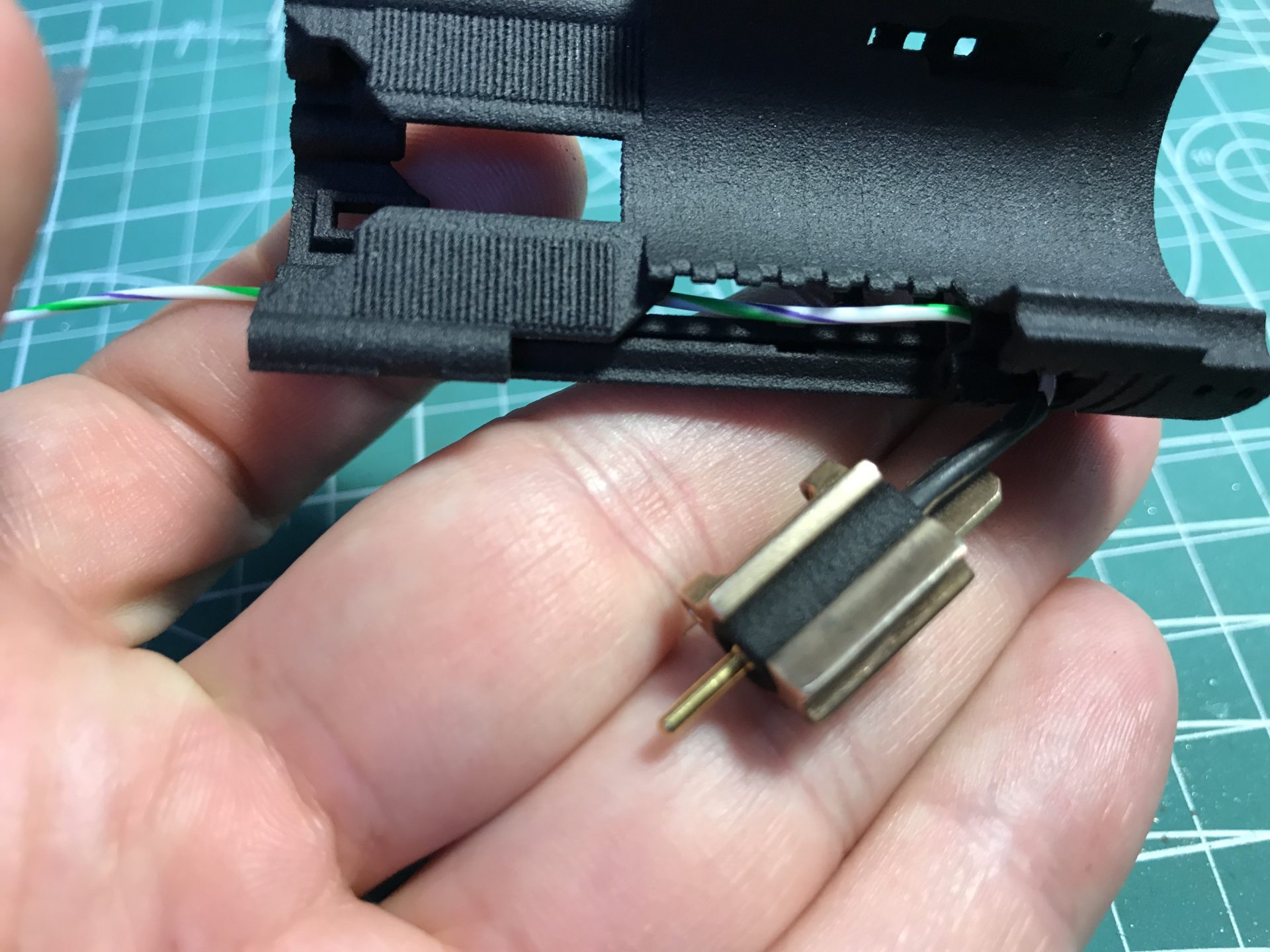
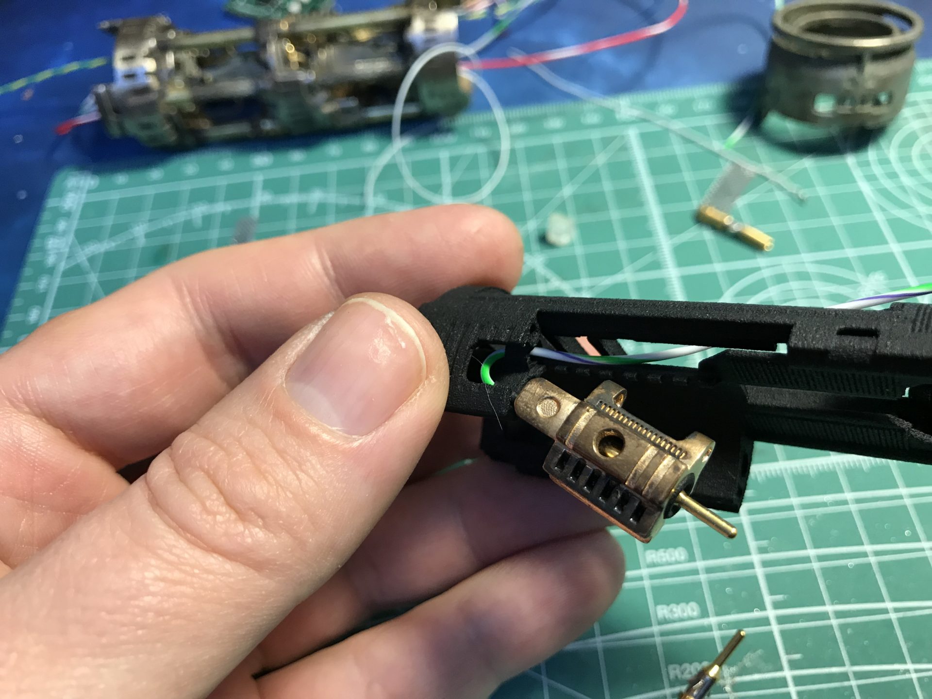
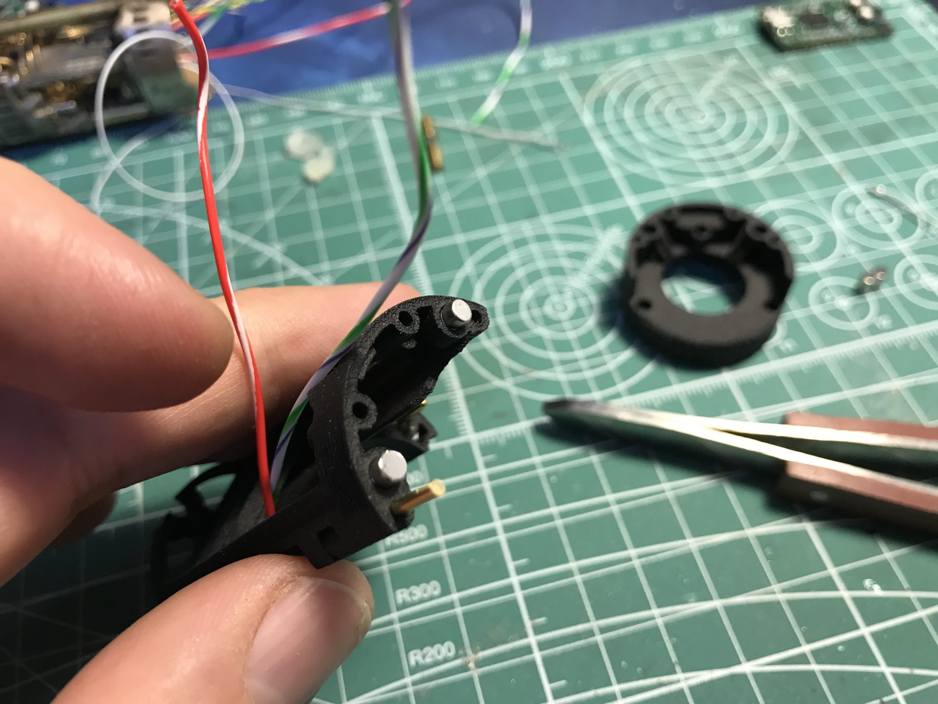
Step 12: Pos pin install. The pin in inserted from the front of the chassis, a widow will allow to push it and exit as shown below. Check that the pin is well blocked and cannot be pushed inward, otherwise, secure it with super glue.
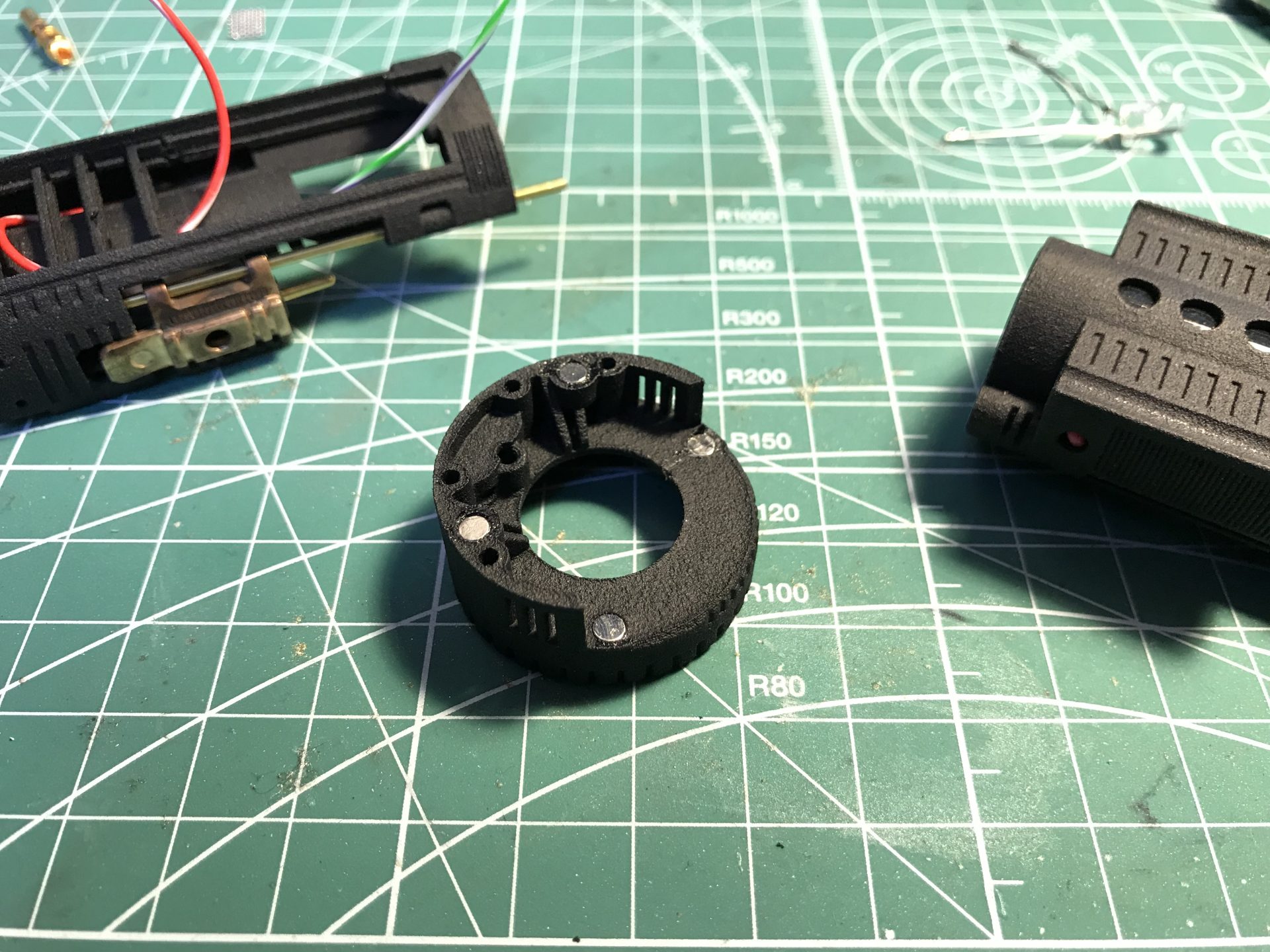
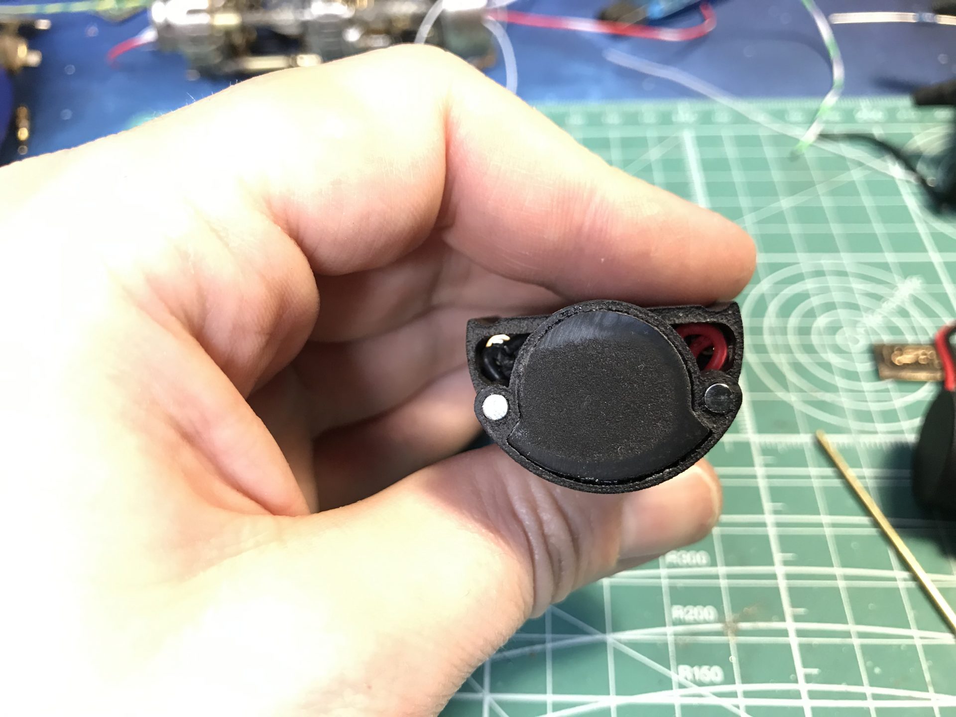
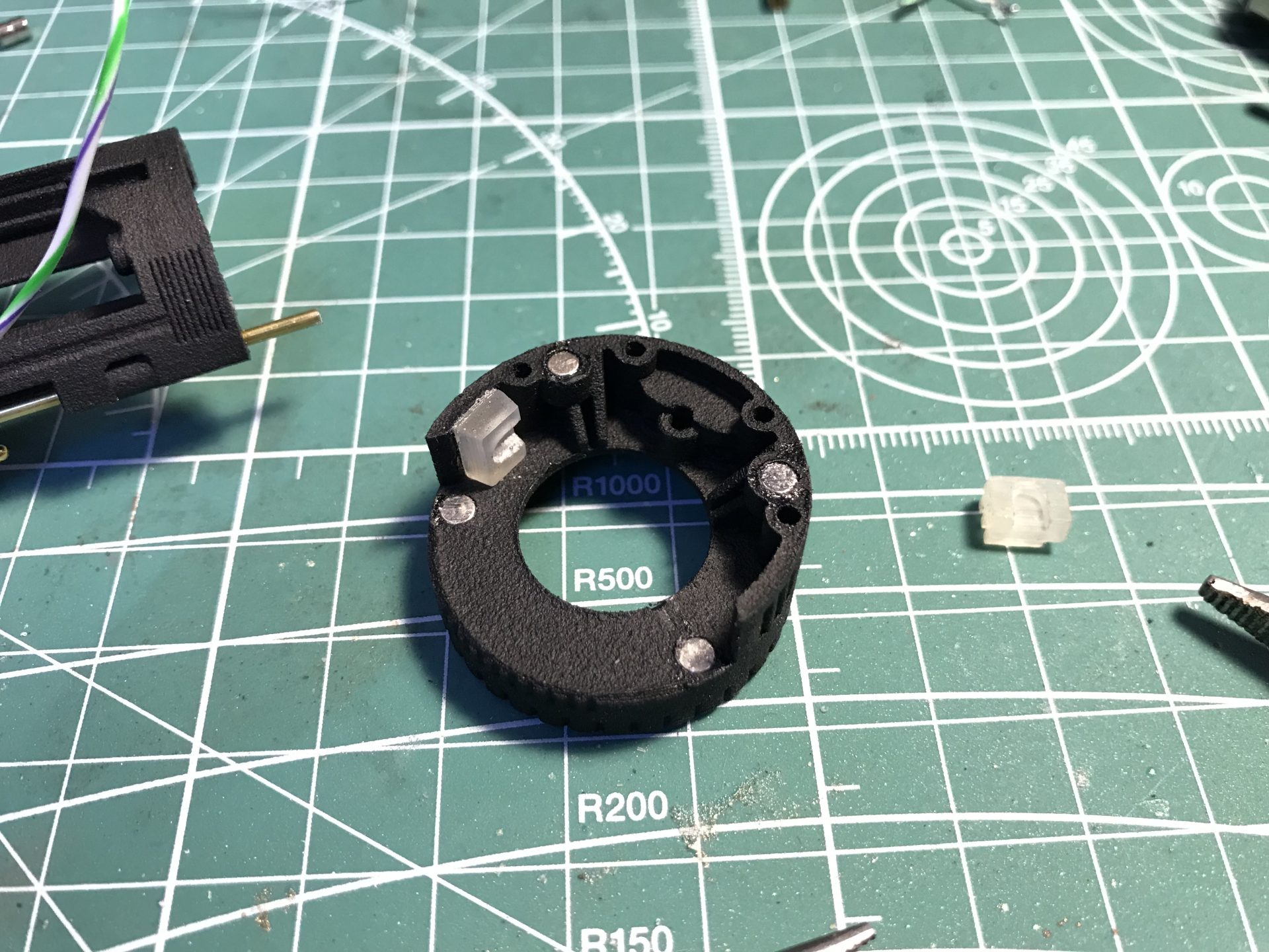
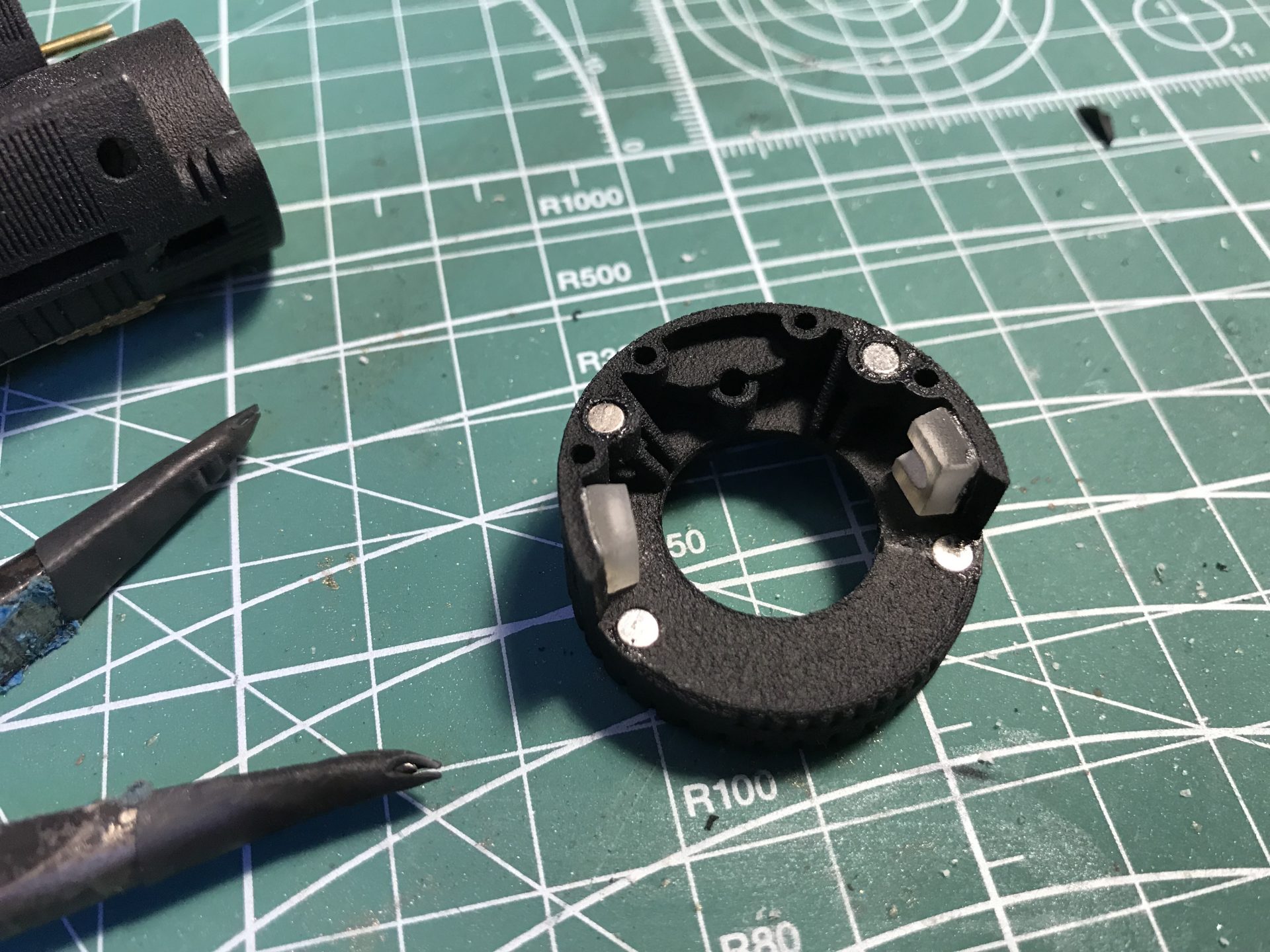
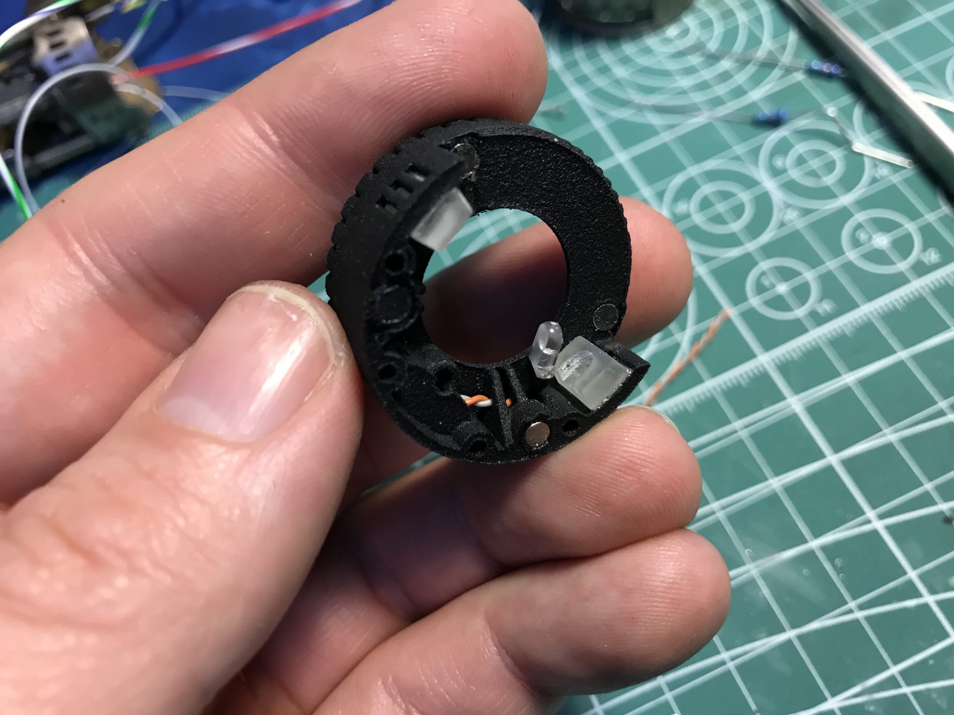
Step 13: Magnets install. The are 2 magnet to glue on the chassis and 4 on the speaker holder (make sure to respect polarities).
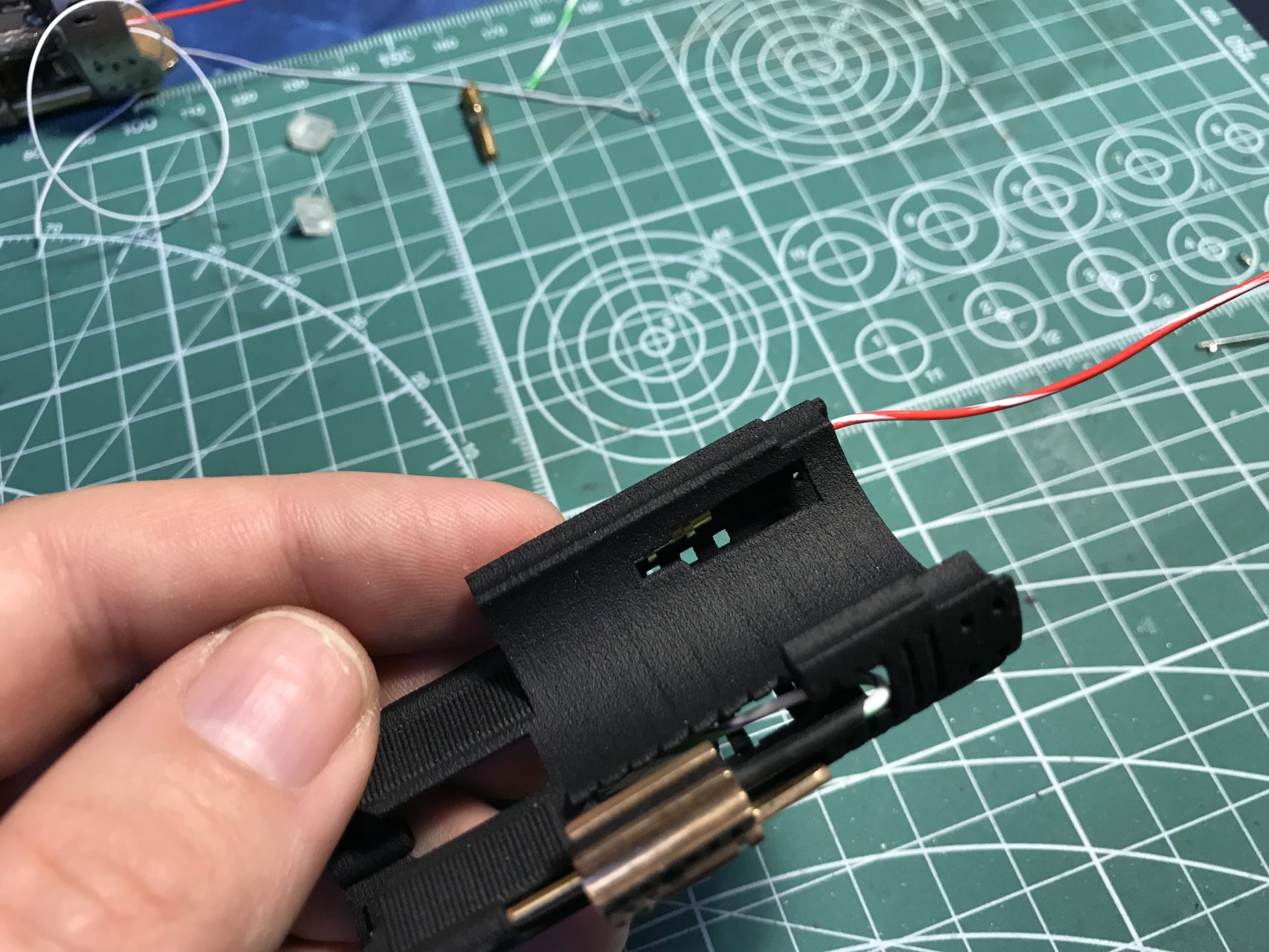
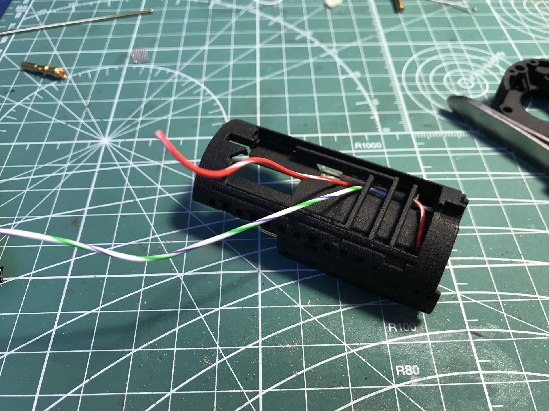
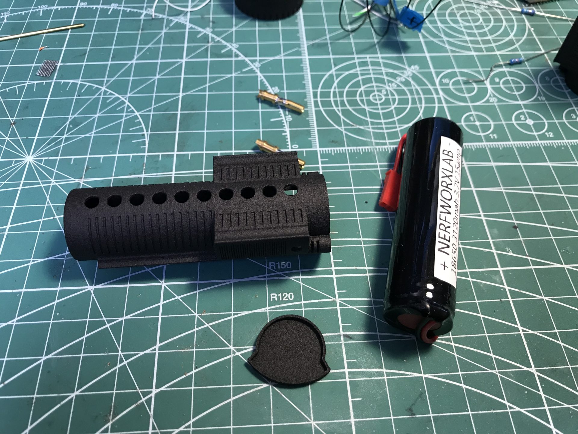
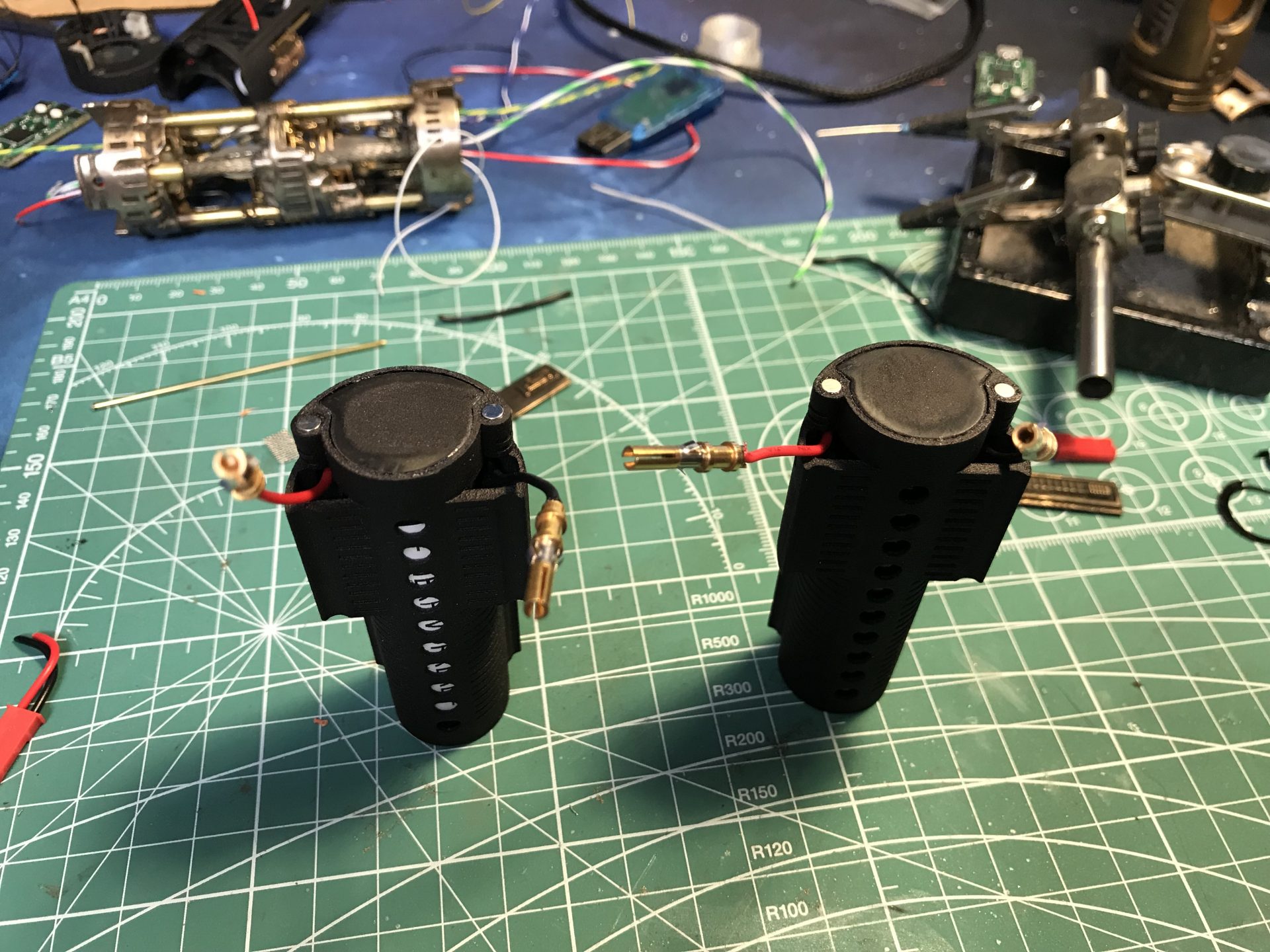
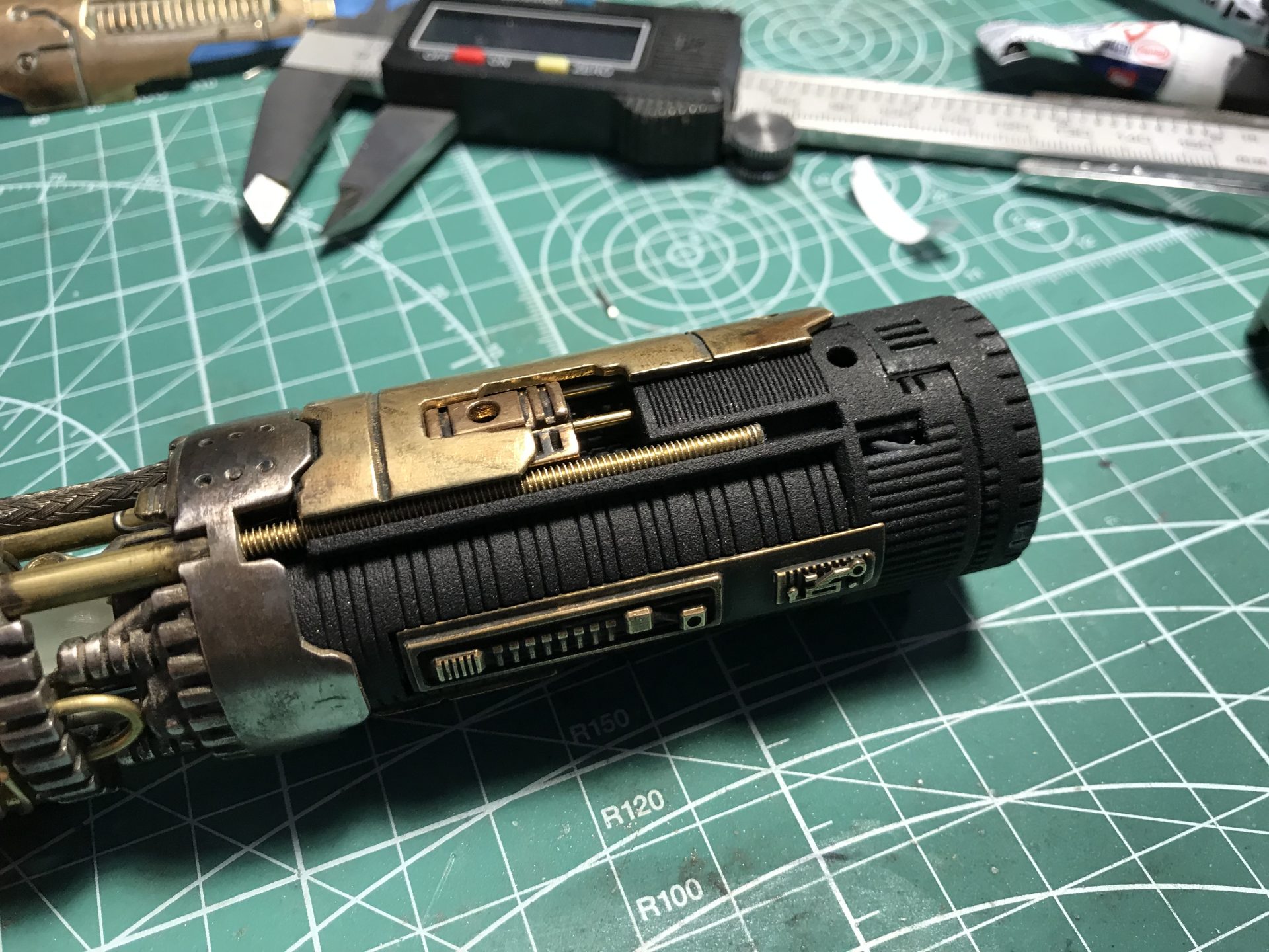
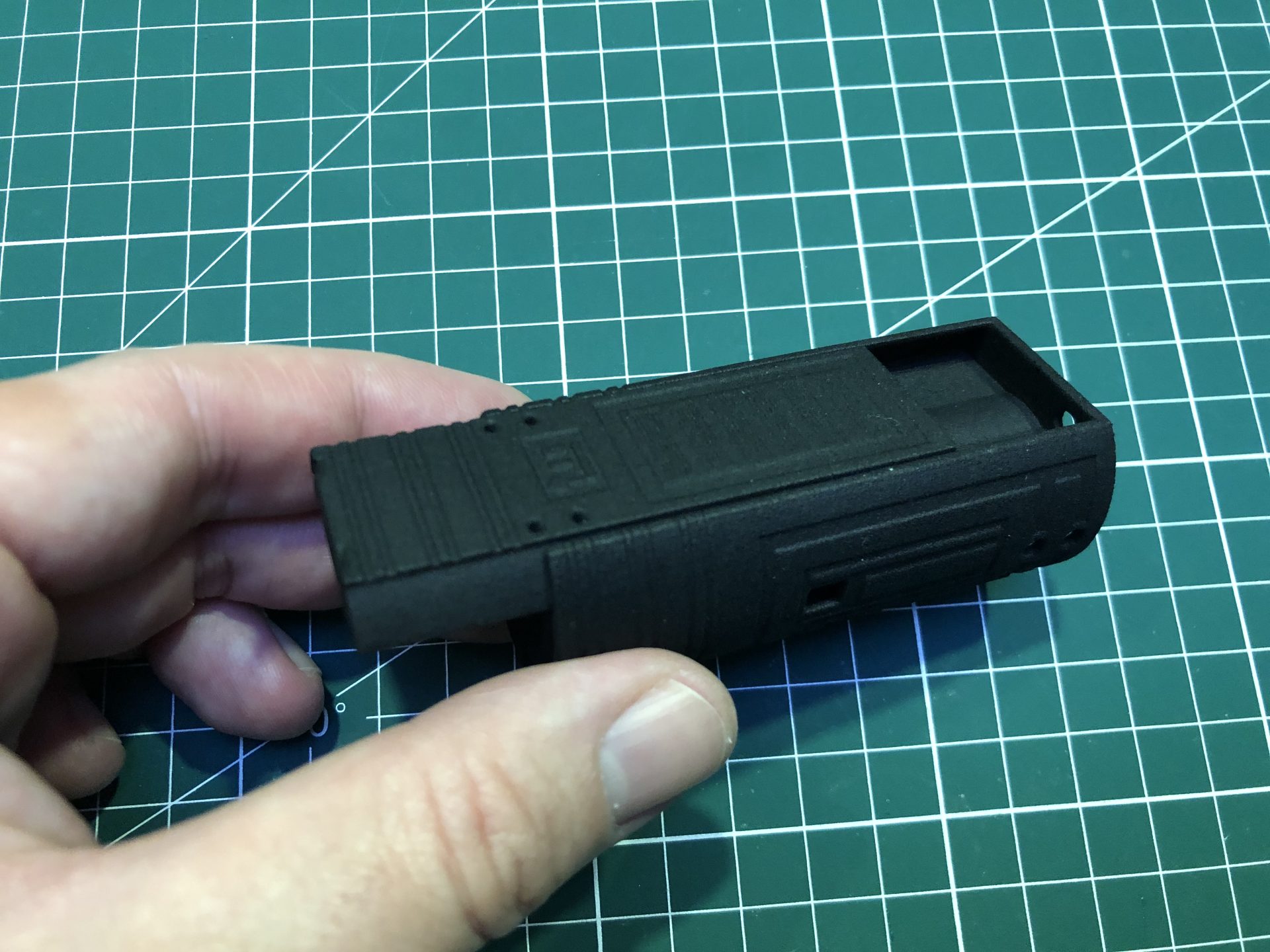
Step 14: Battery install. The chassis uses pre-wired 18650 15A batteries and 2 ore more battery packs can be created.
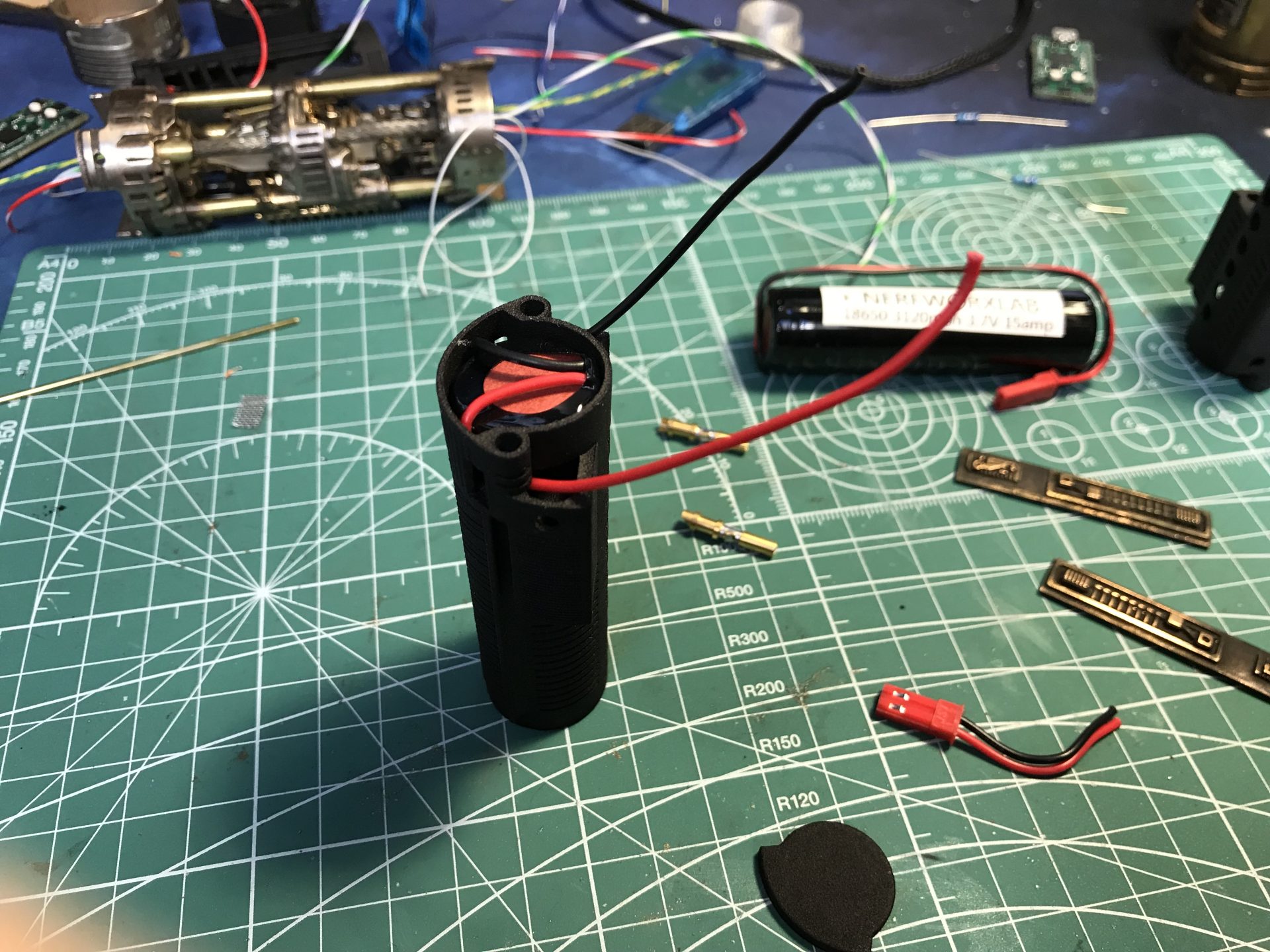
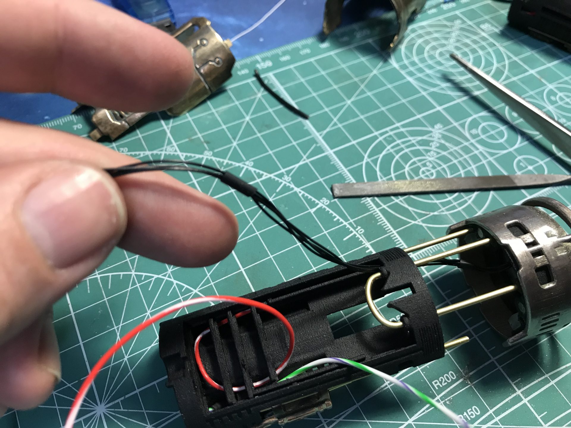
Insert the battery in the holder, with the wires exiting from the back.
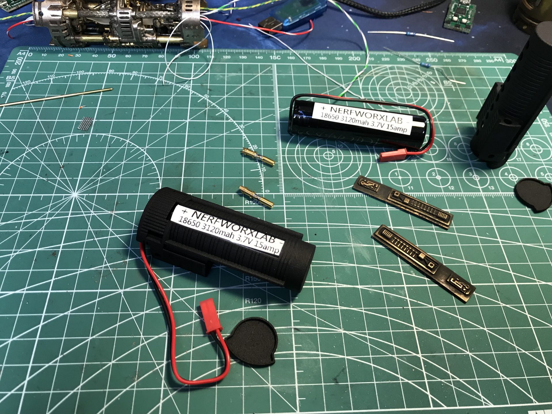
Bend the wires back inside as shown below (make sure to respect pos and neg sides, as installed on the chassis). Then shorten the wires calculating that the brass pins sockets can double back inside.
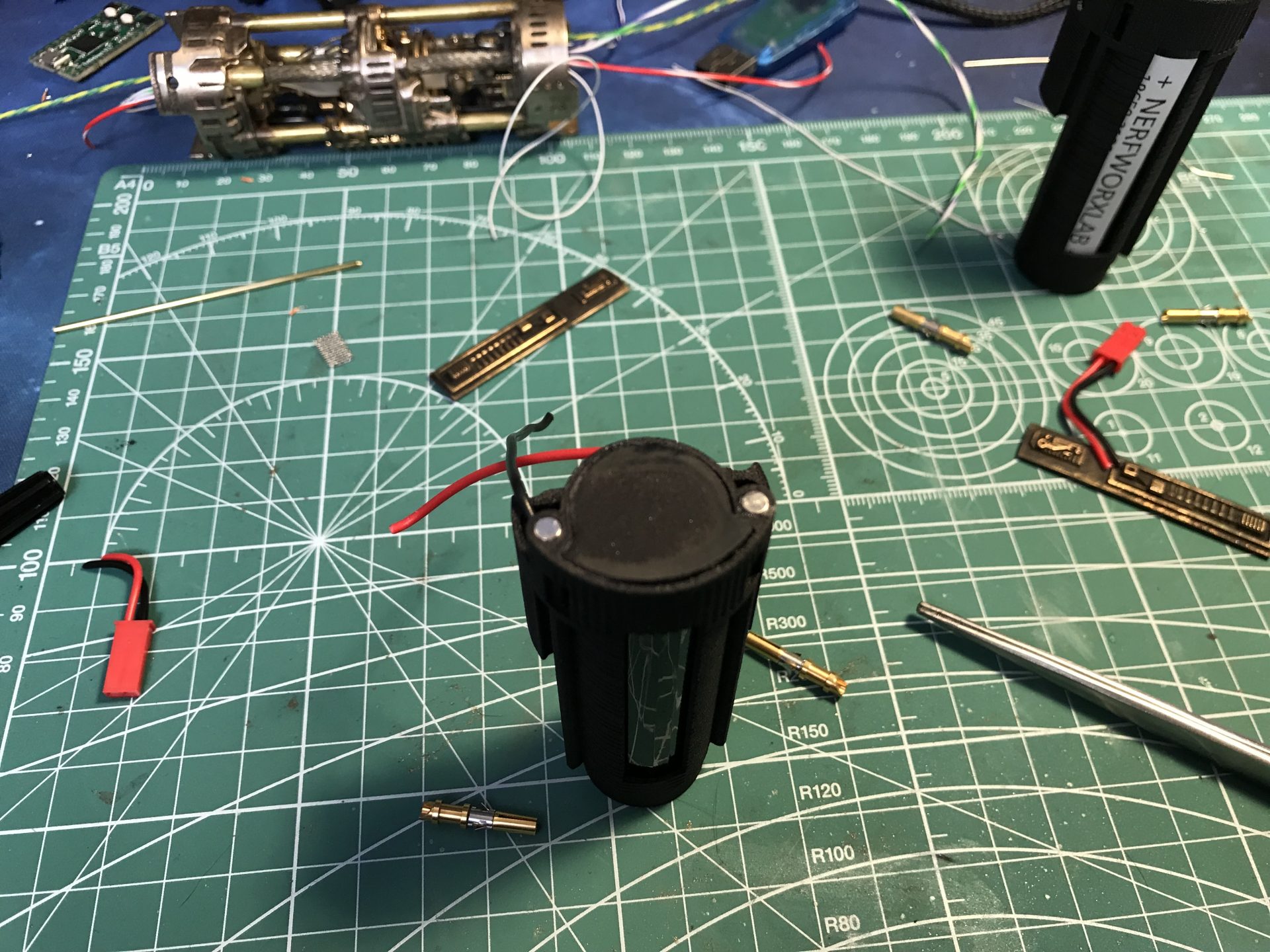
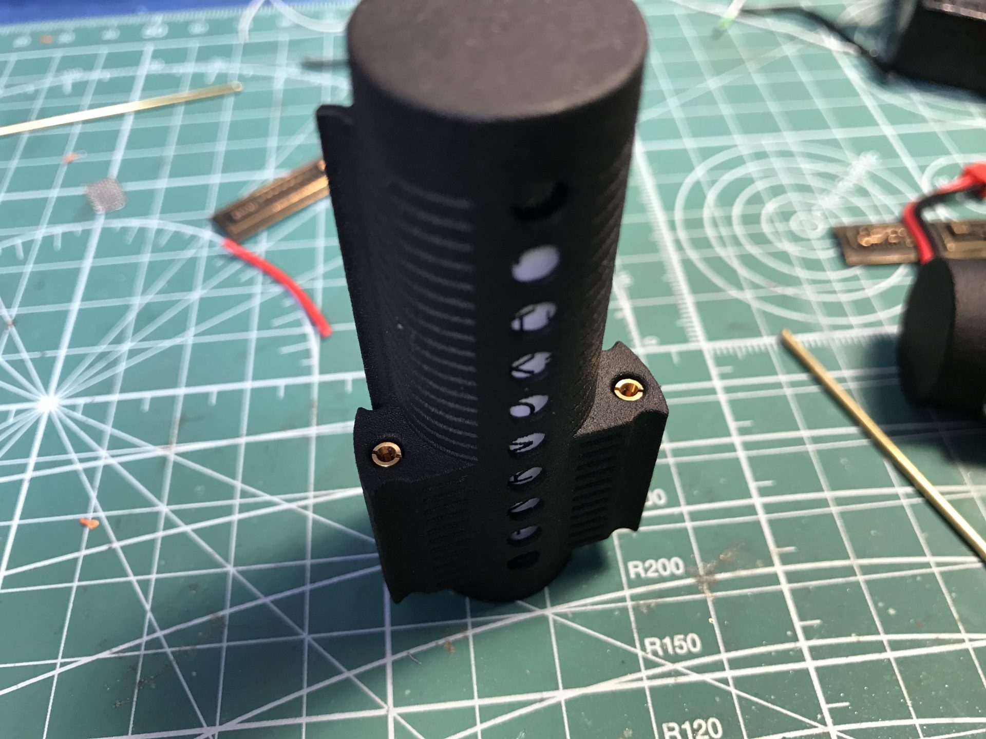
Press and glue the cap over the wires. Make sure to press hard to make the bottom perfectly flat (sand the bottom is needed).
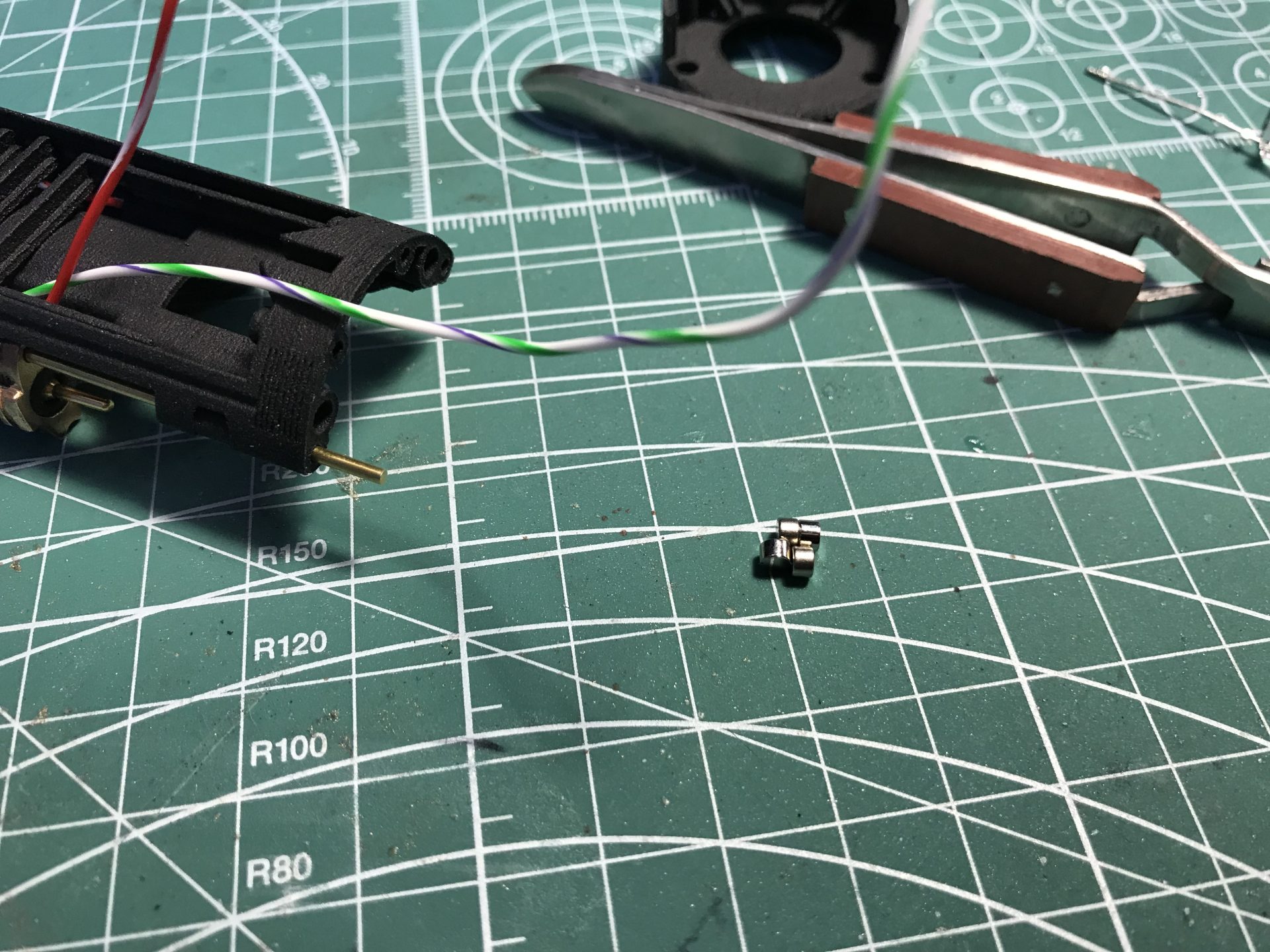
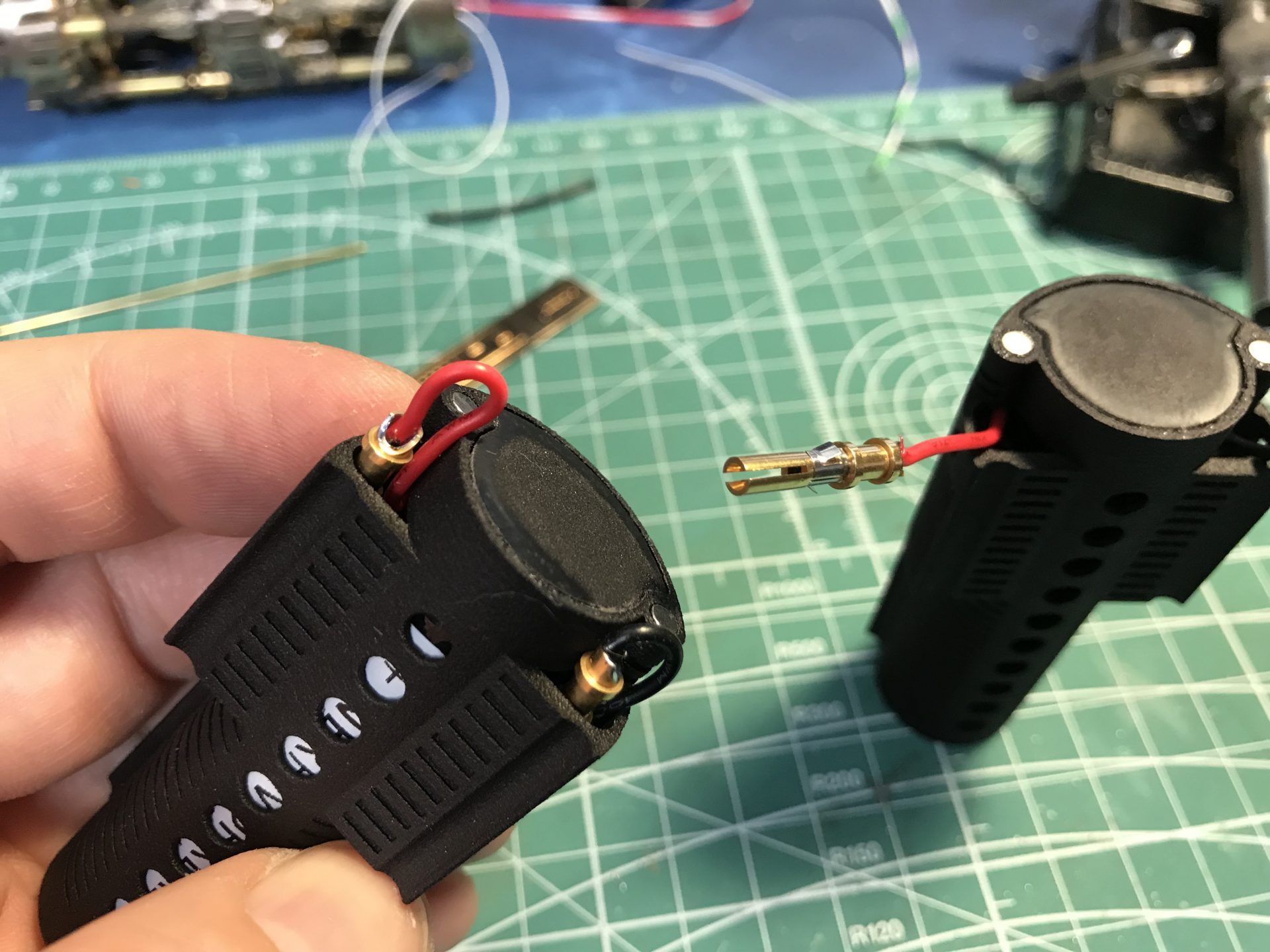
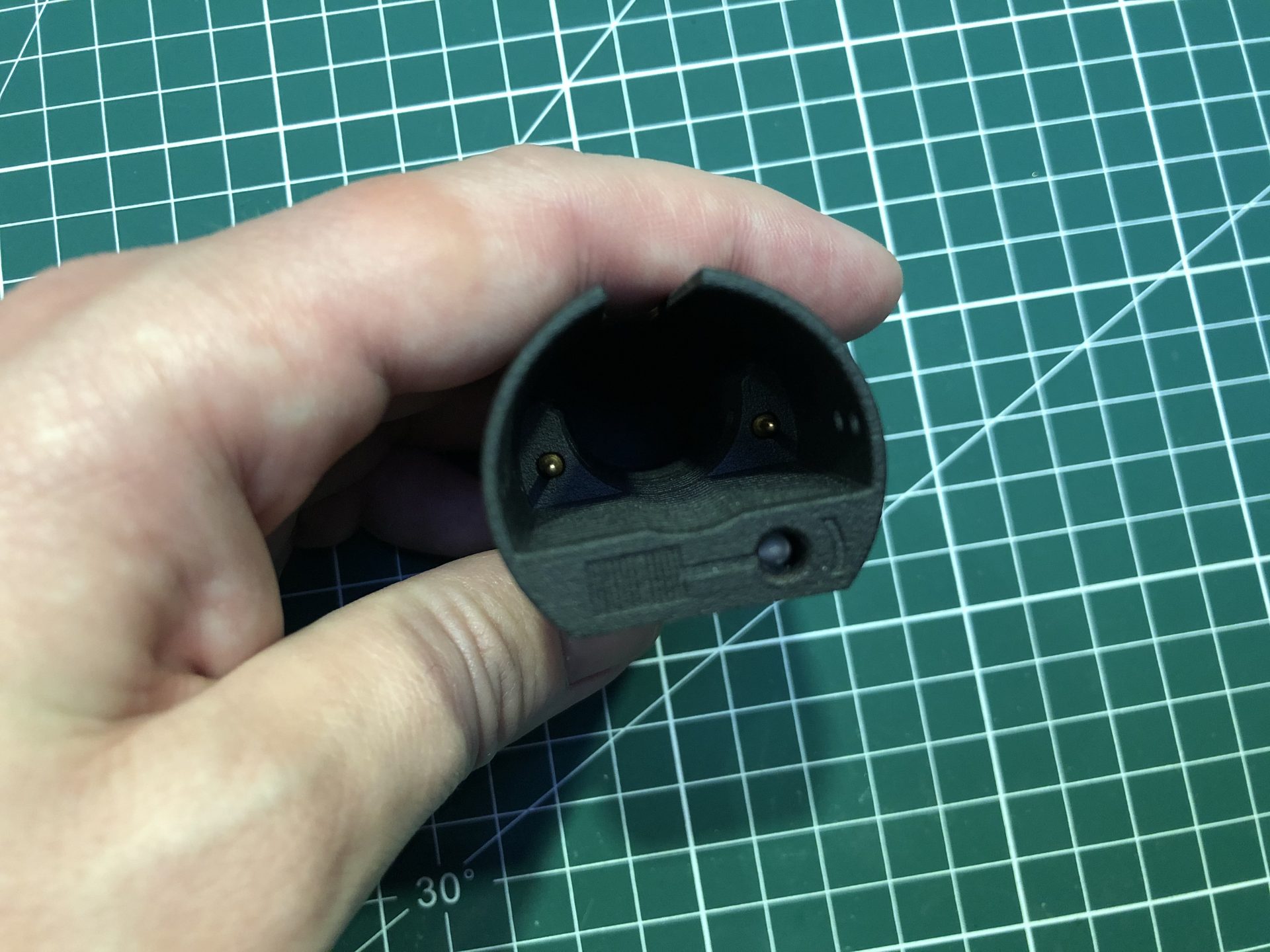
Glue the 2 remaining magnets (again making sure to respect polarities with the chassis ones). And next, solder the brass pins sockets.
Before installing the brass pins sockets in their place, test them with a male pin, to ensure they are neither too loose or to hard when inserting the pin (expand or press down the female pins accordingly).
Install them as shown below (make sure they are locked or add a bit of glue to secure them). Then push inside the excess of wire.
Step 16: Test the assembly. It is important to check that the switch is behaving properly, meaning that it stays in place when inserted into the battery pack, or stay disconnect. Depending on the wire used, it can create pressure and push the switch to ward the battery. if this happens, the lip at the back of the switch can be bent a bit outward, so that it will friction fit with part 13 and keep power off.
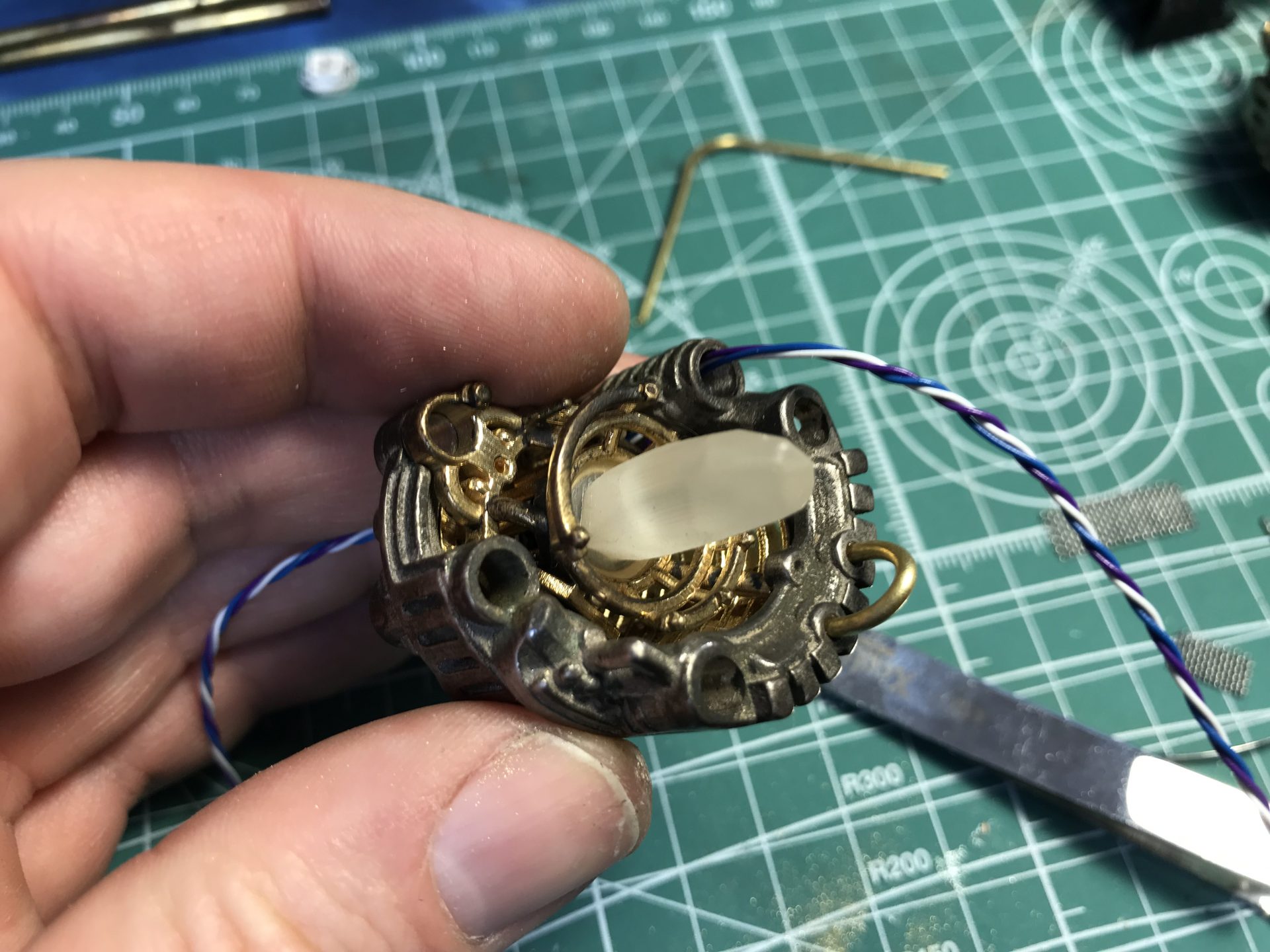
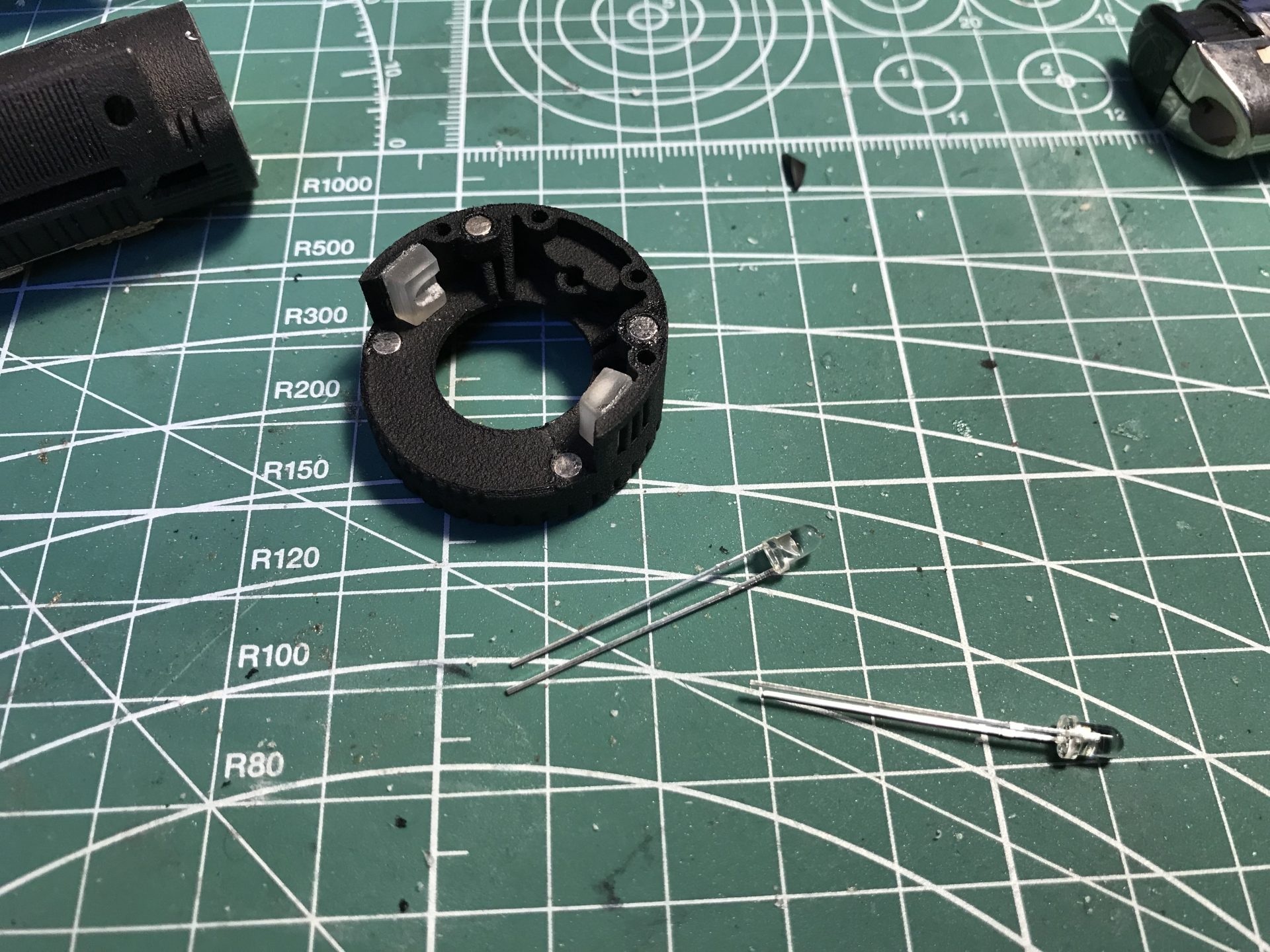
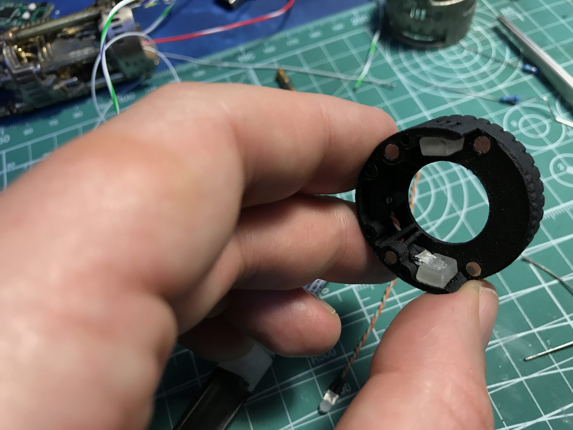
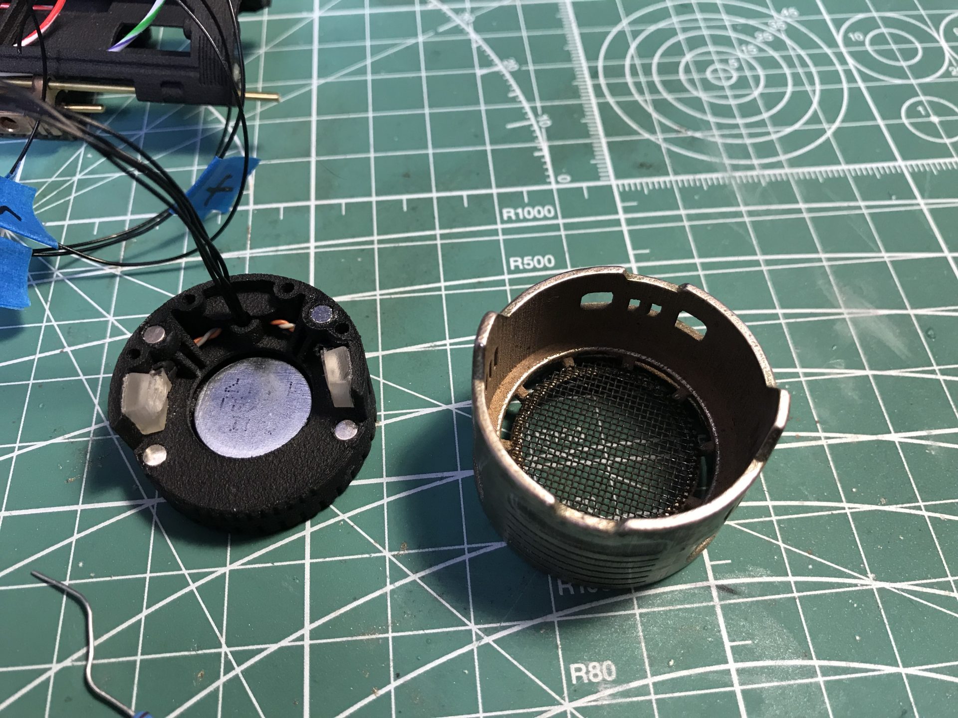
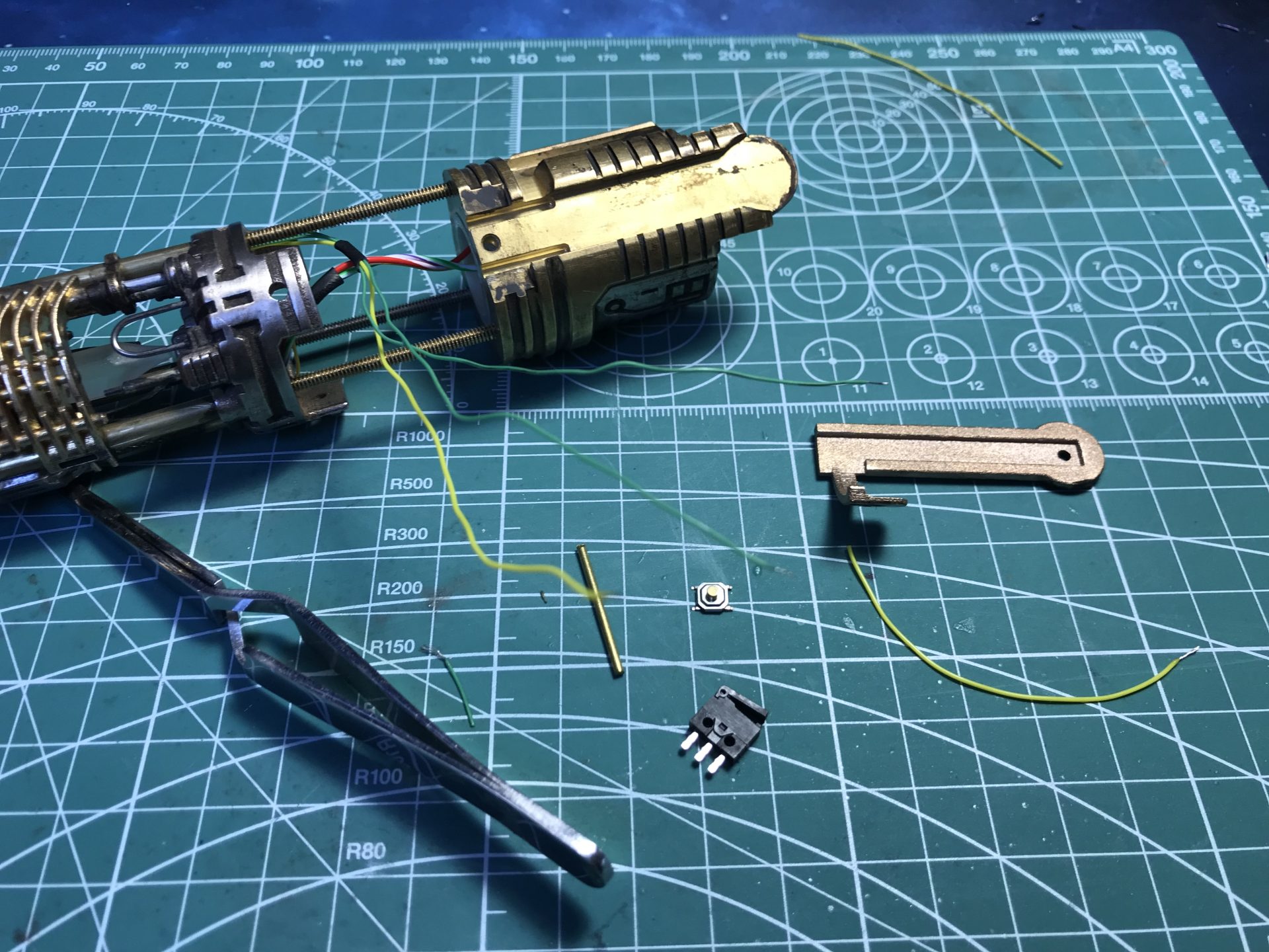
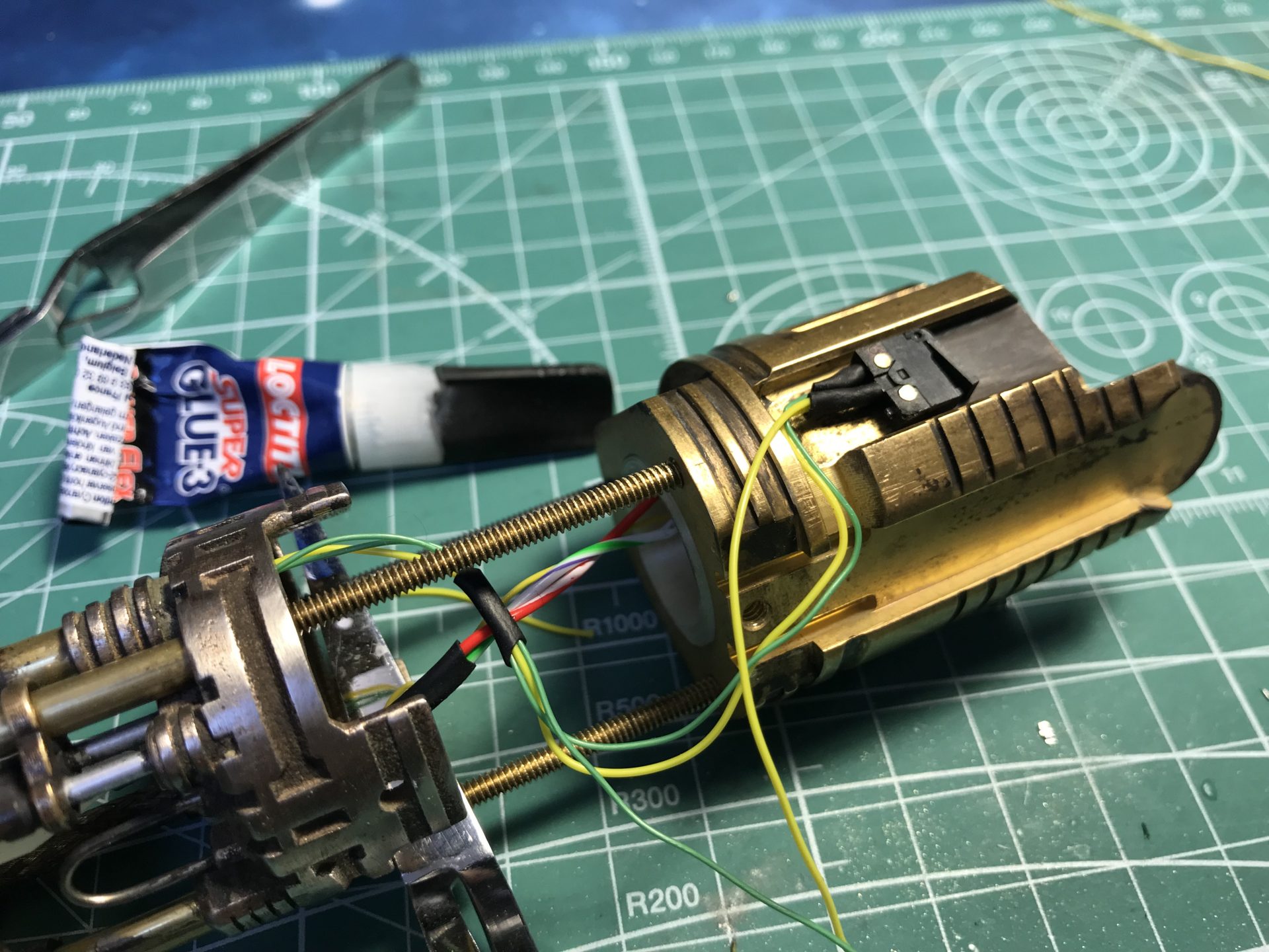
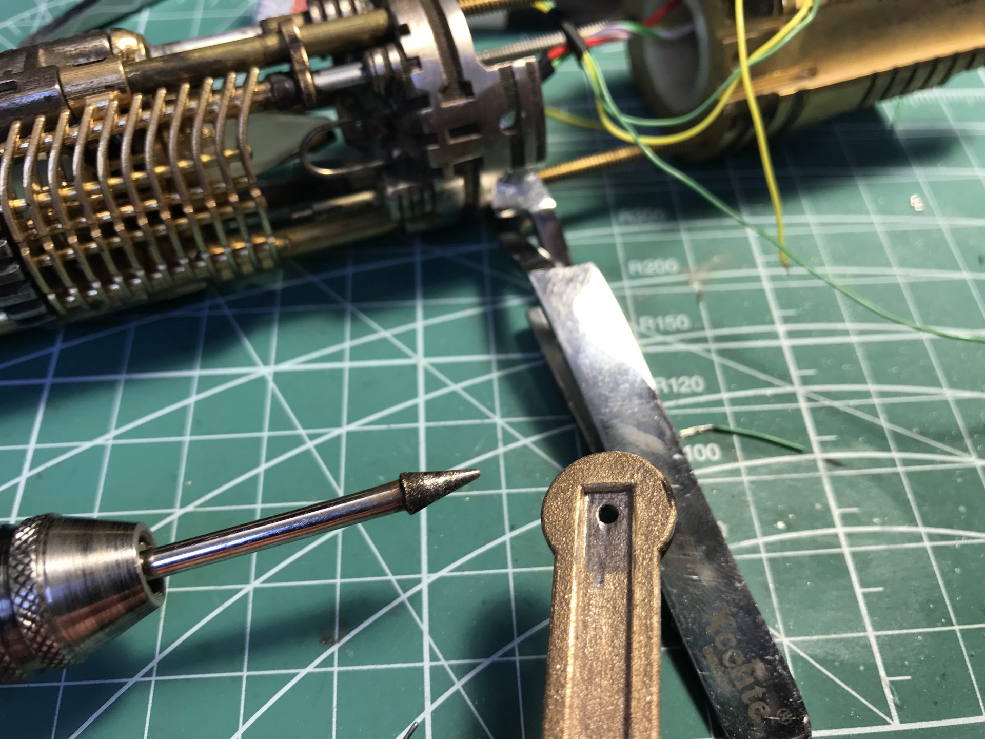
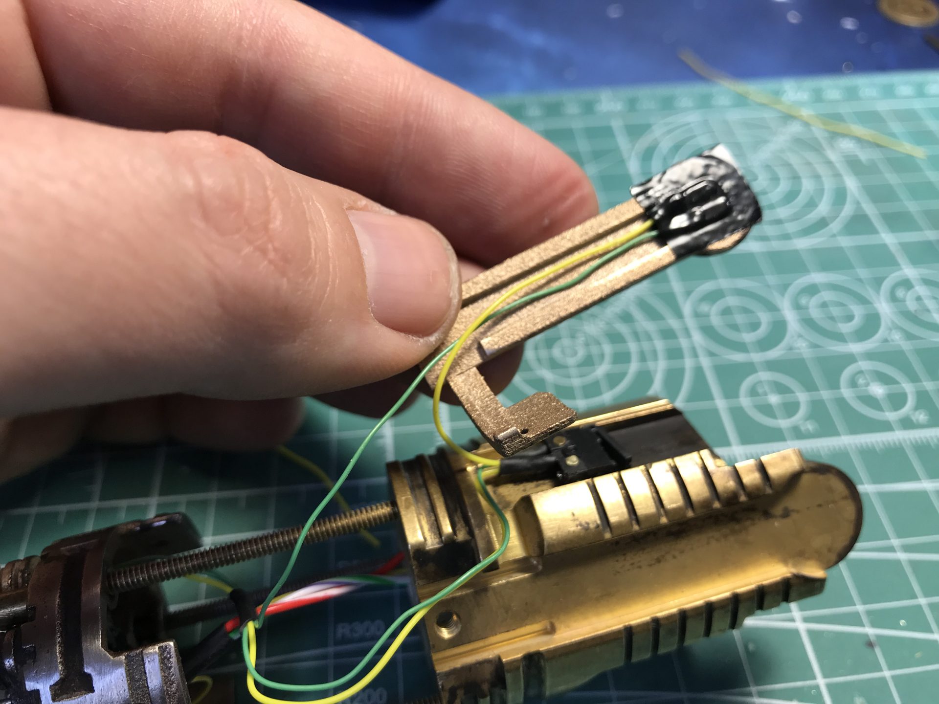
Step 17: Power led indicators install. Cut away the 2 little frosted plastic led holders. They need to be glued into the speaker holder as shown below. Pliers will be required to press and glue those 2 pieces in place. if they don’t insert properly, it is ok to sand the 3 prongs. Once glued, test that the speaker holder locks properly on the power cell part.
Two 3mm leds are to be inserted in these plastic pieces. The leds have to be sanded as flat / small as possible, and their leads cut as short as possible. There isn’t much space for them and the install is a bit tricky. The wires pass through small holes and exit on the speaker side.
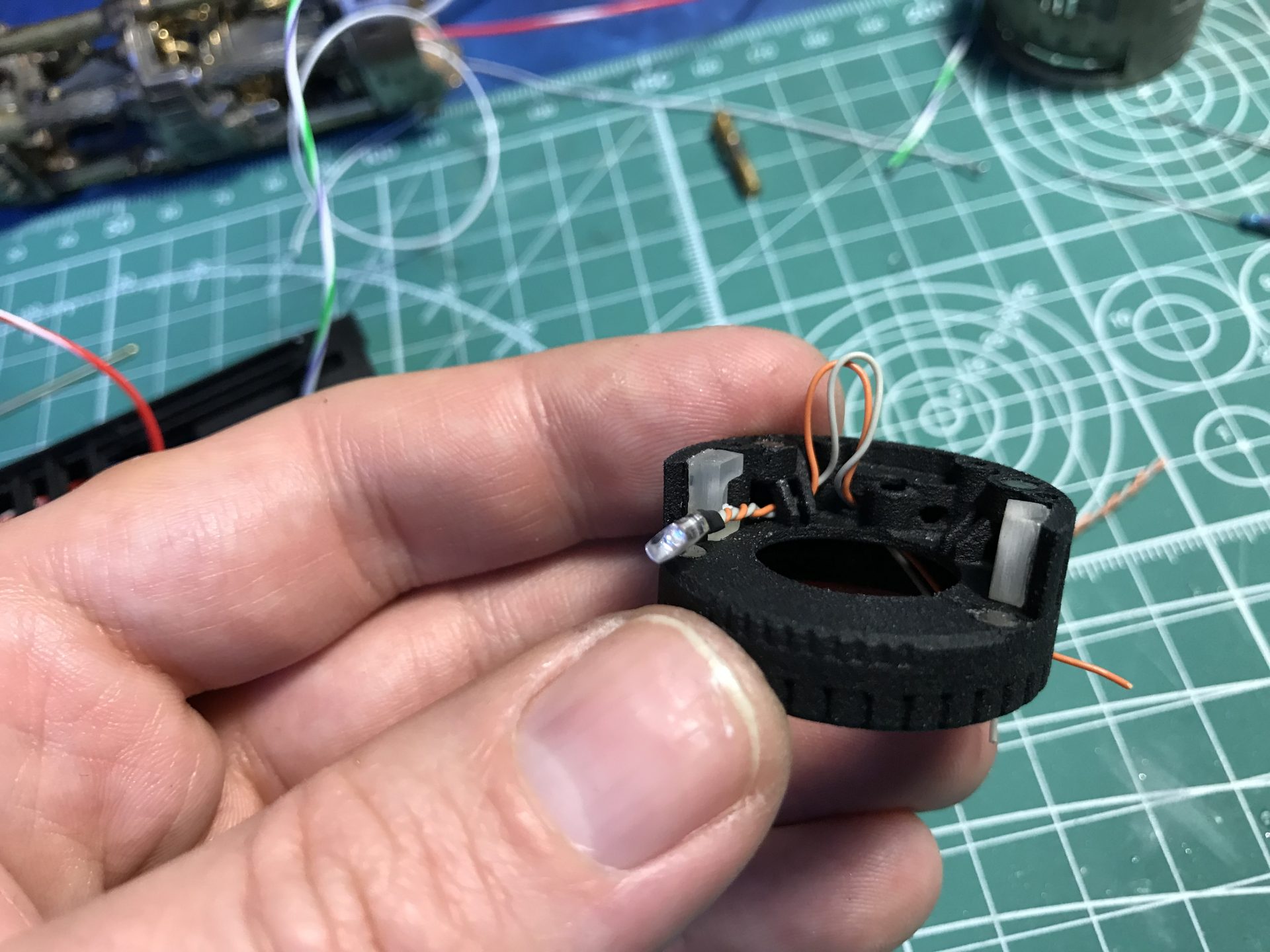
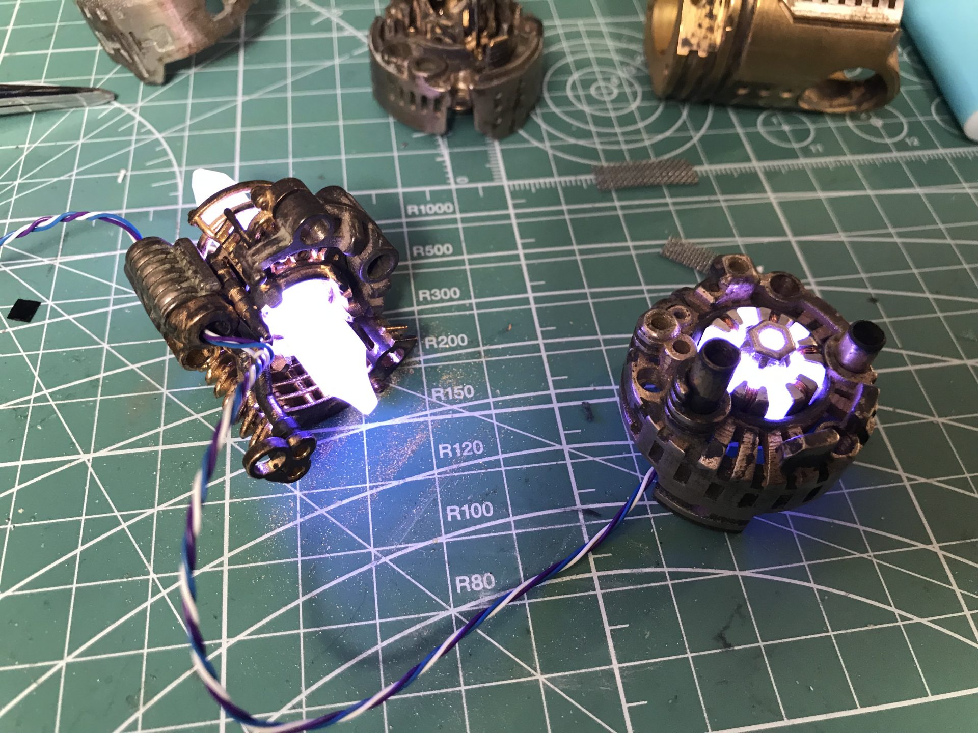
Then the led is pressed into plastic part (glue can be added to secure it).
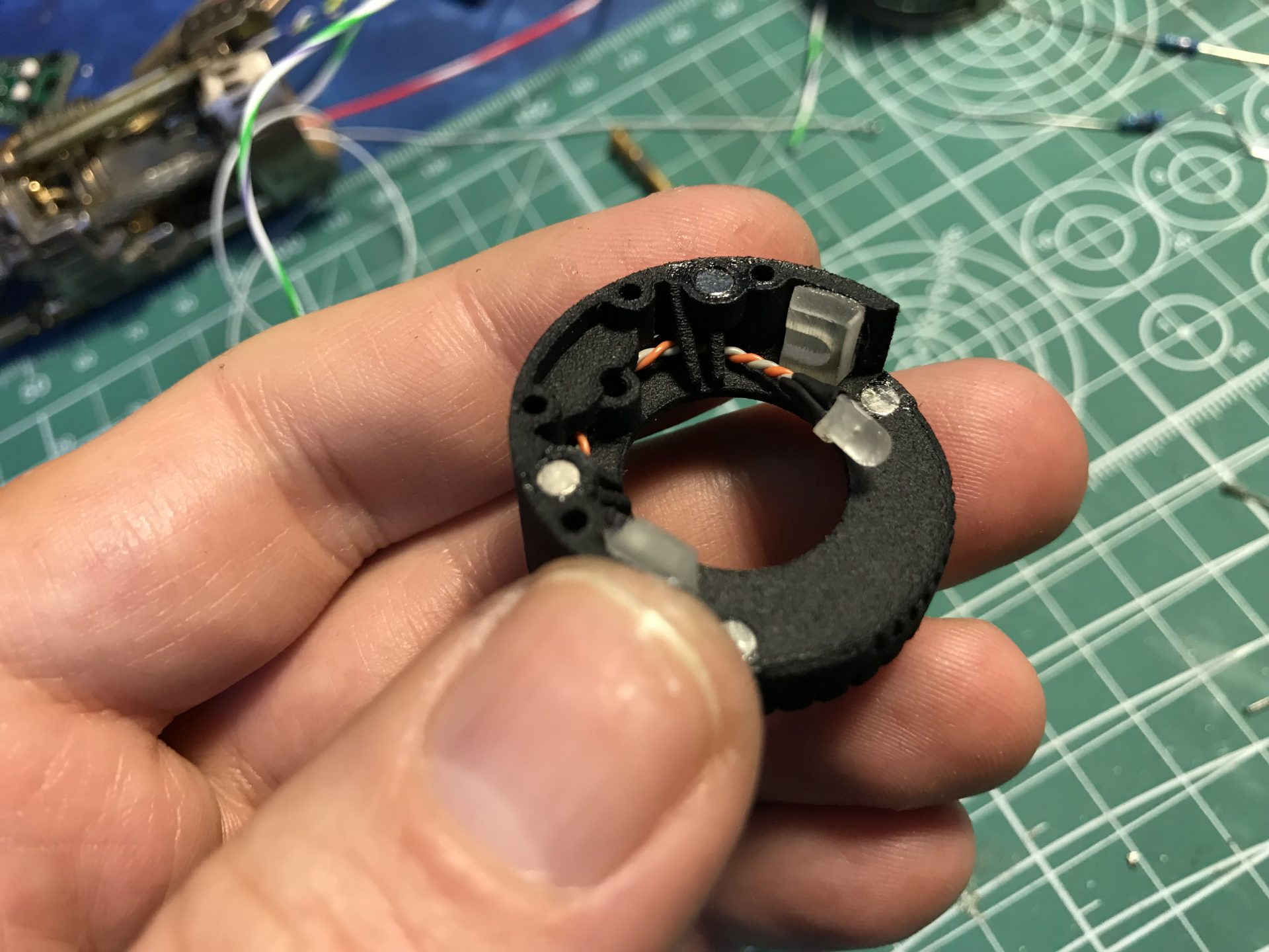
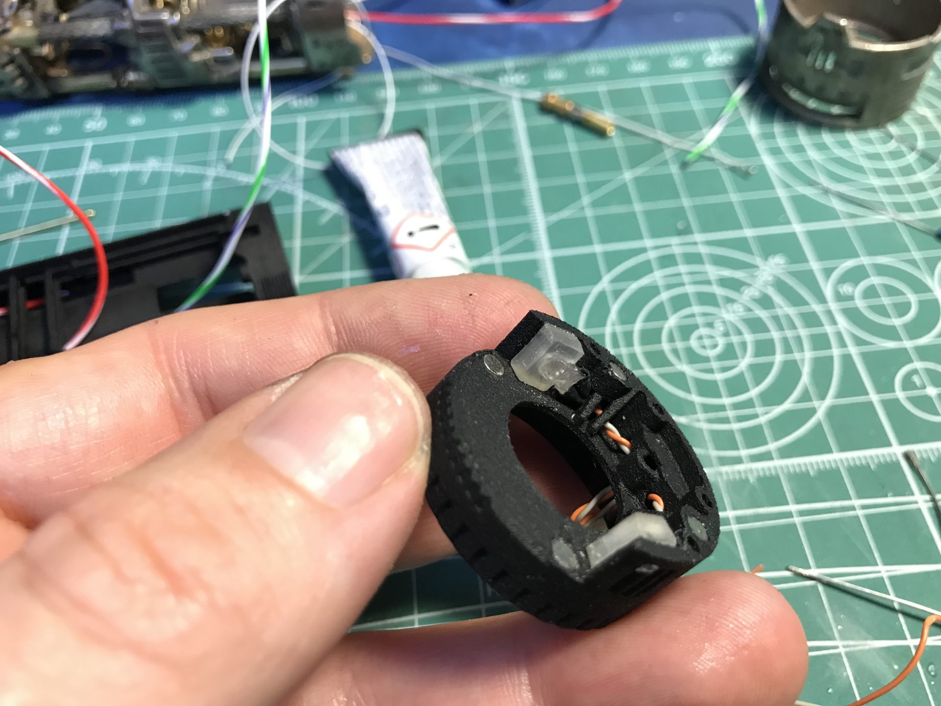
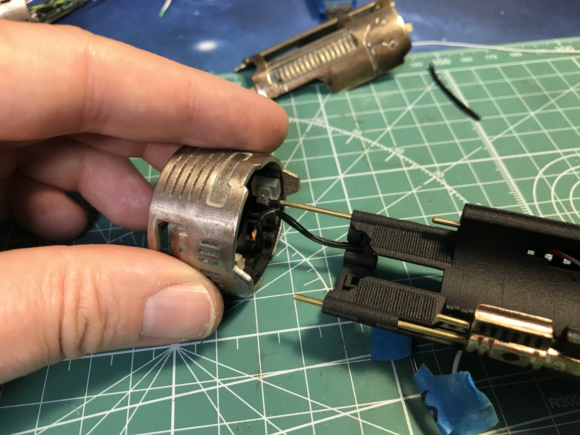
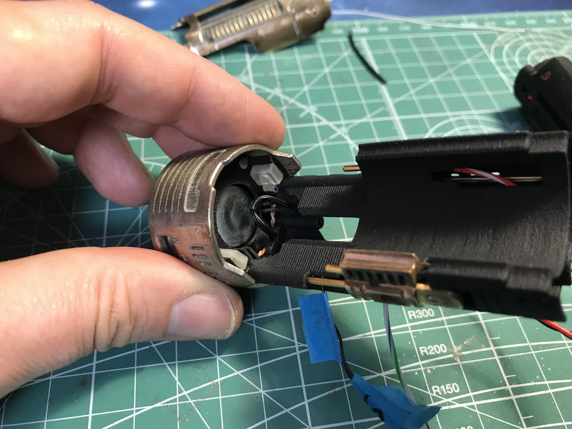
Step 18: Speaker install. First bridge both leds wires on the speaker side, and add the speaker and its wires (make sure the speaker sits flat and secure it with glue).
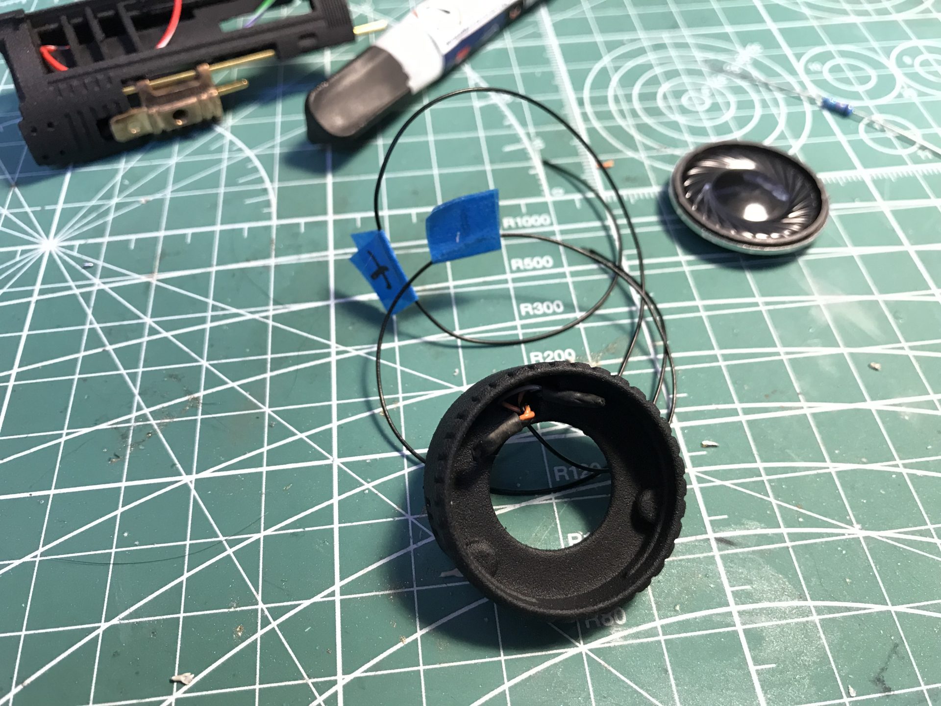
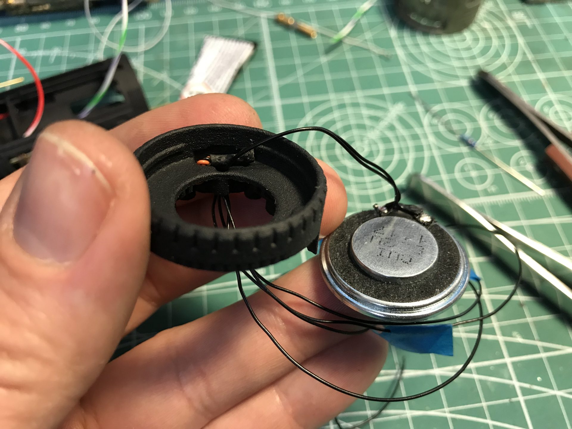
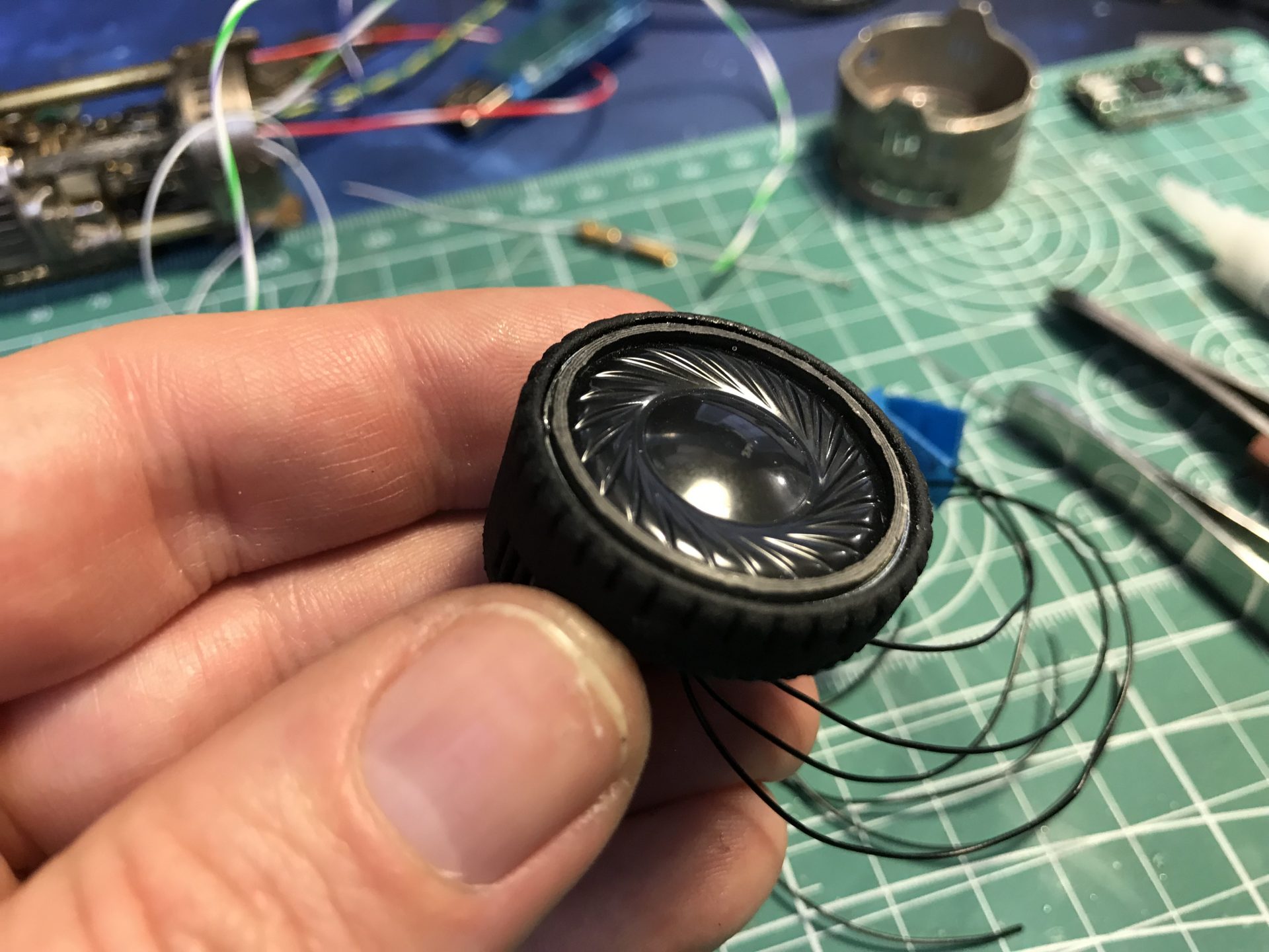
Step 19: Wire can be added on the speaker shell. Use epoxy to secure it. Then add the speaker module into the speaker shell (make sure to have tested the components before, and make sure the speaker module fully slide into the bottom of the shell). It is not recommended to glue the shell on the speaker holder, but instead use double sided tape or similar to provide enough adherence, while still allowing to dismount the shell if necessary.
Then, glue the 1.5mmOD rod if not yet done.
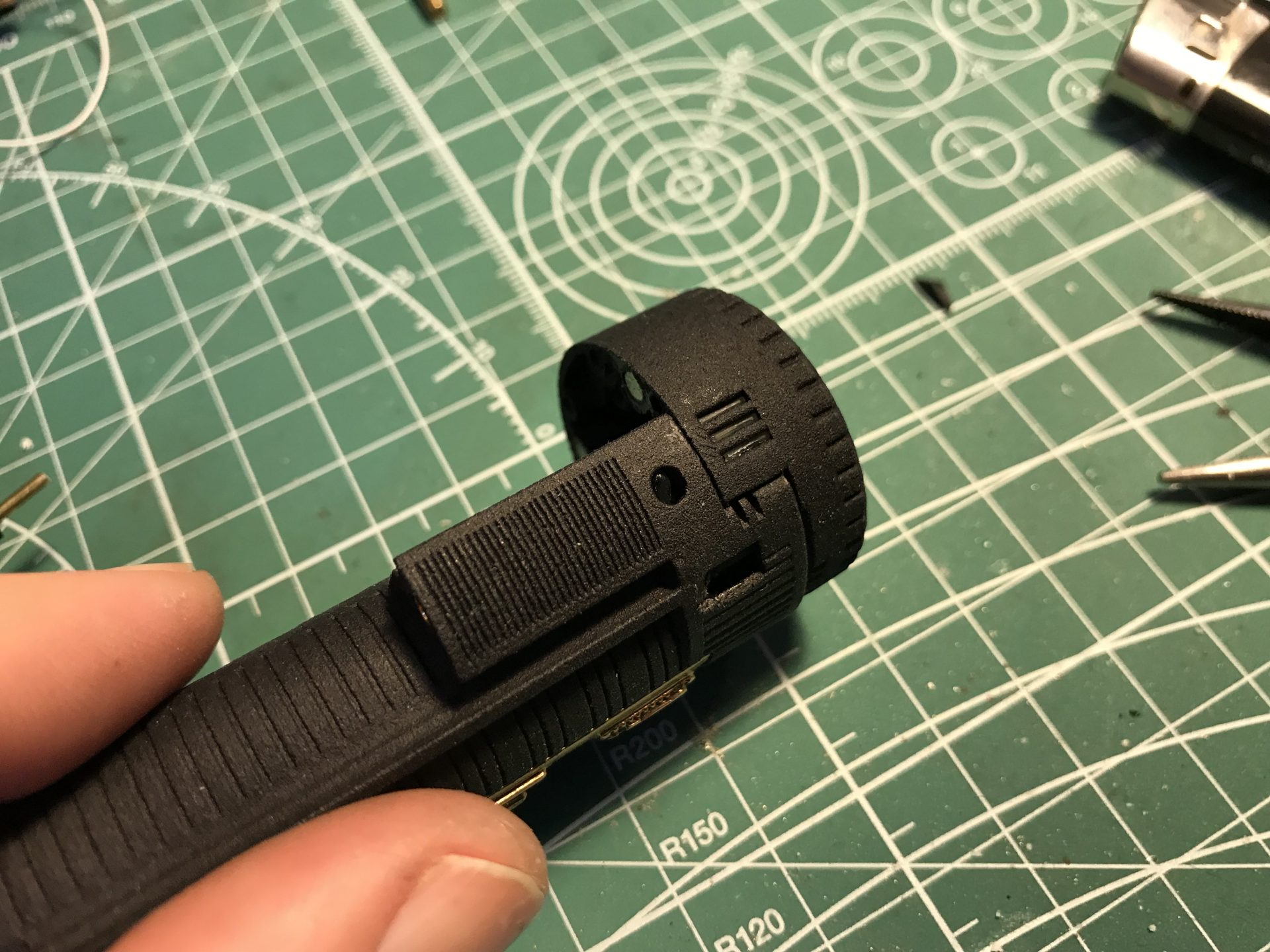
Step 20: Test the speaker assembly fitment with the battery and part 16. It also serve to locate where to exactly glue part 13 on the power cell.
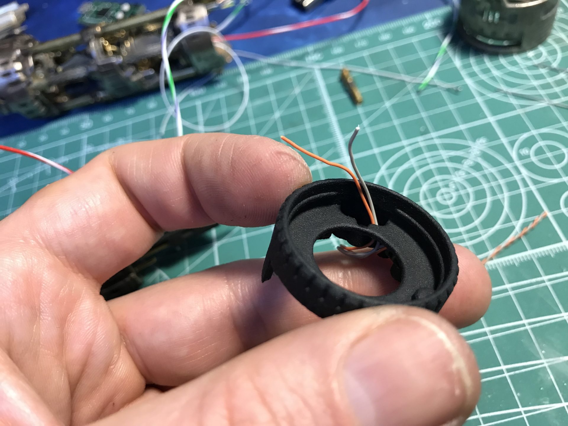
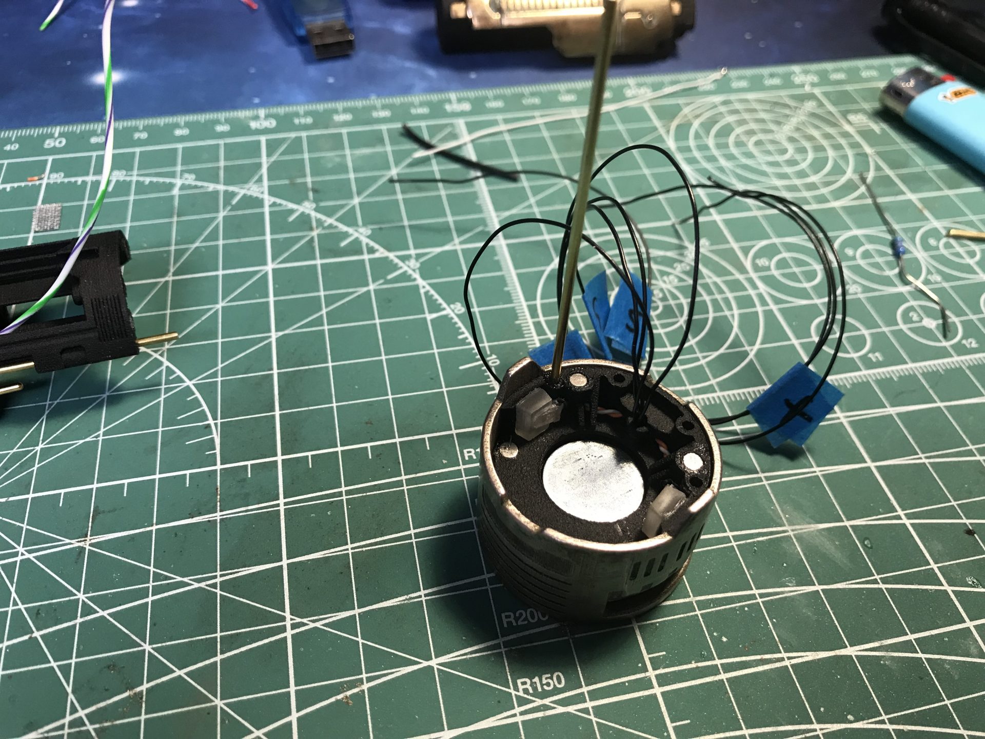
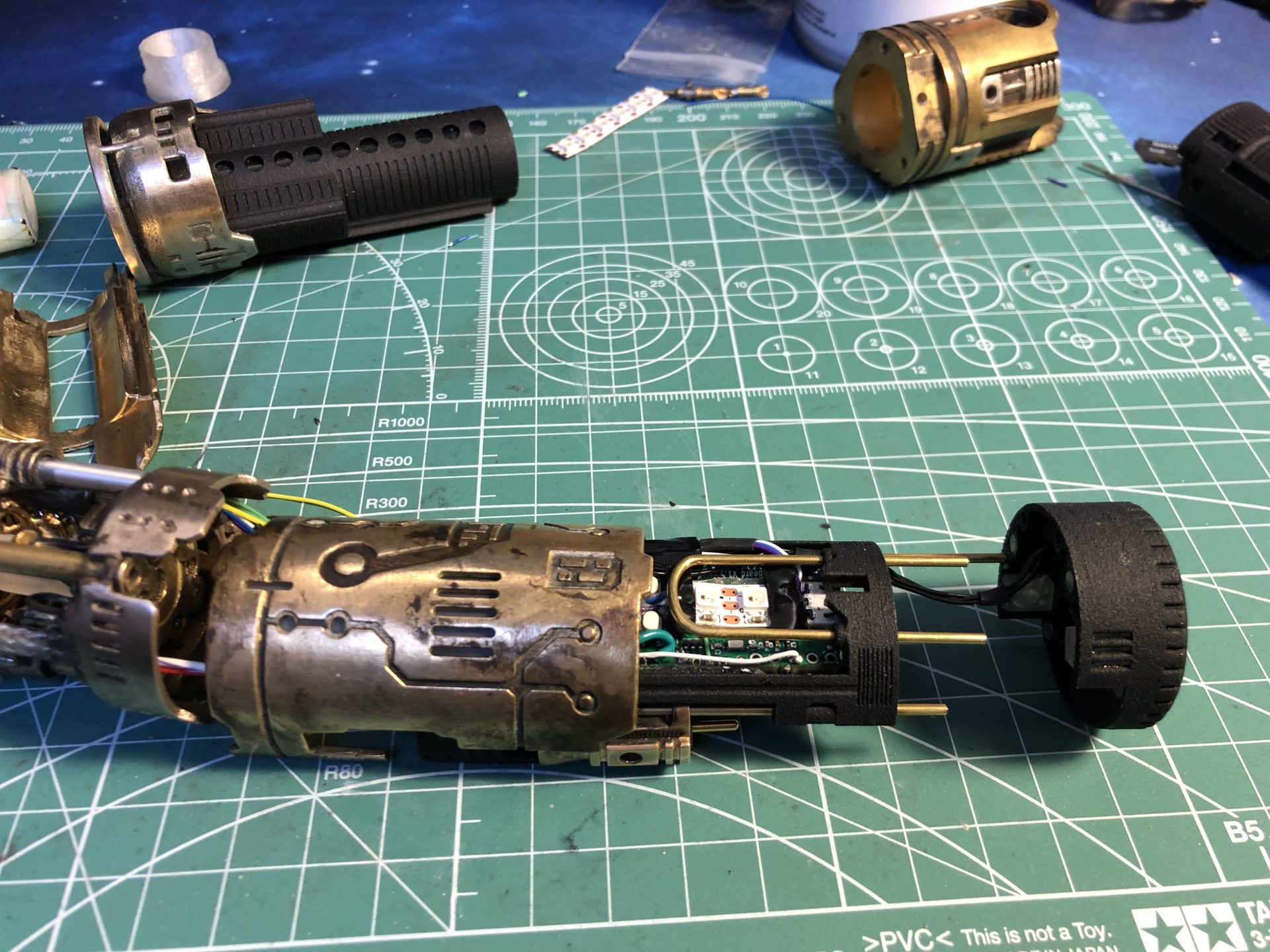
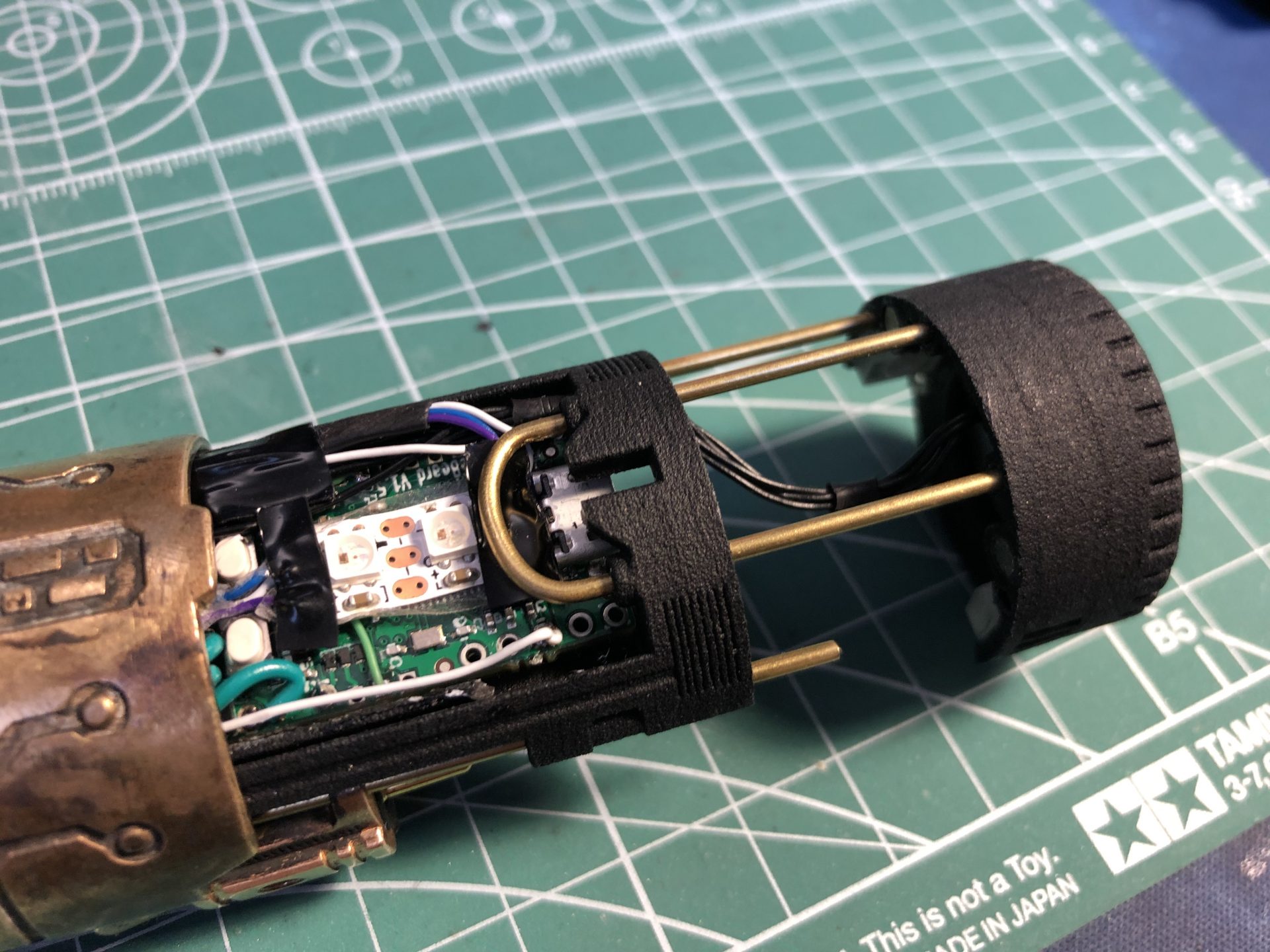
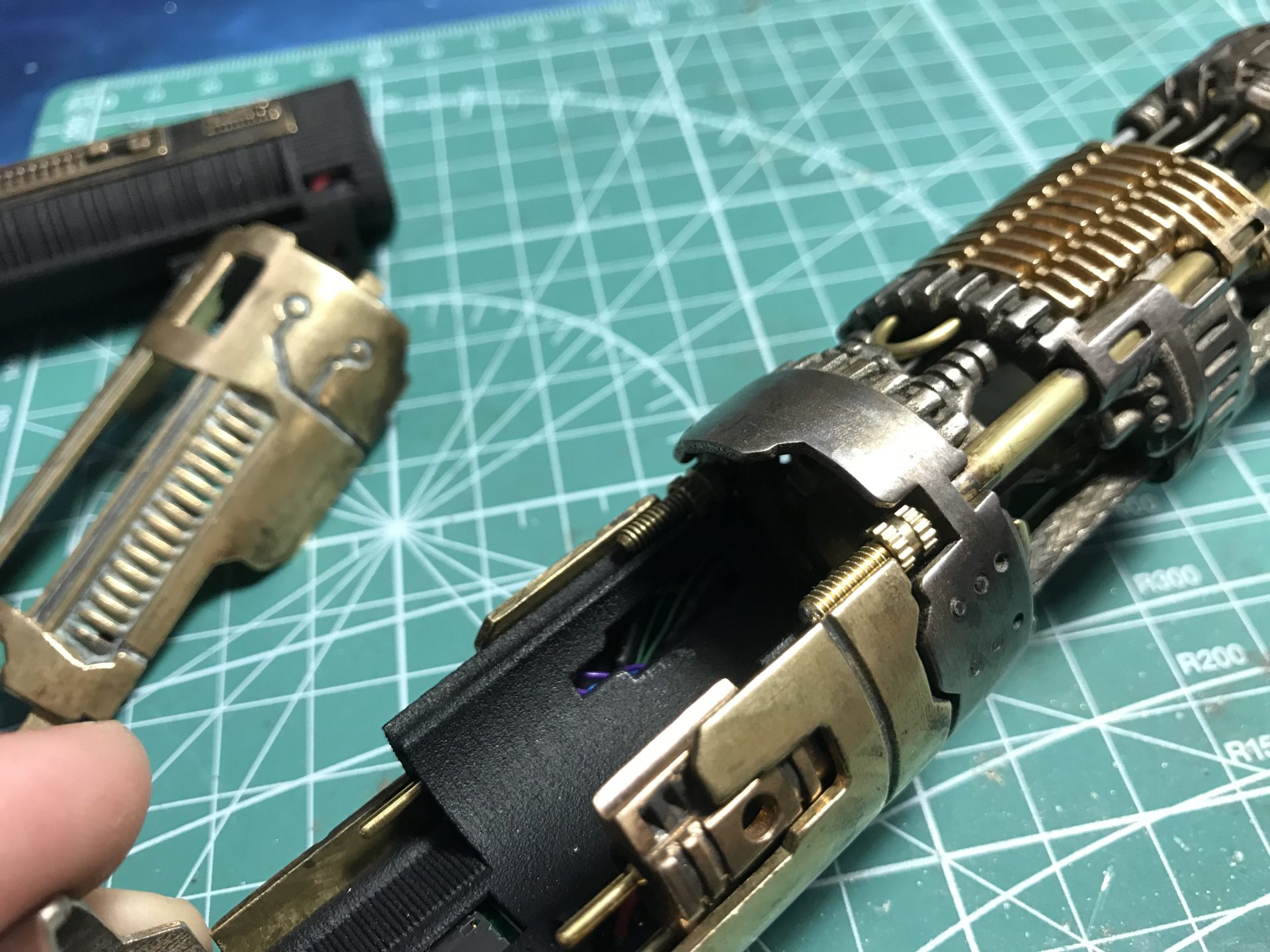
Step 21: Pass the speaker and led wires through the right or left holes in the main chassis. The needed length is to allow the power cell to be removed. Heatshrink can be added to make sure the wires stay together when the speaker is closed, as well as to lock the wires in the hole at the right length.
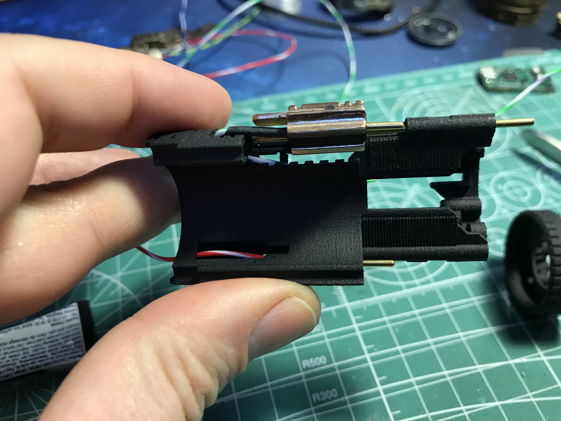
Step 22: Prepare the U shaped 1.5mmOD rod, it will serve as stopper for the speaker module assembly. Do not glue it yet and the soundboard needs to be installed first. This step is to test the fitment and ensure that the rod passes over the board properly.

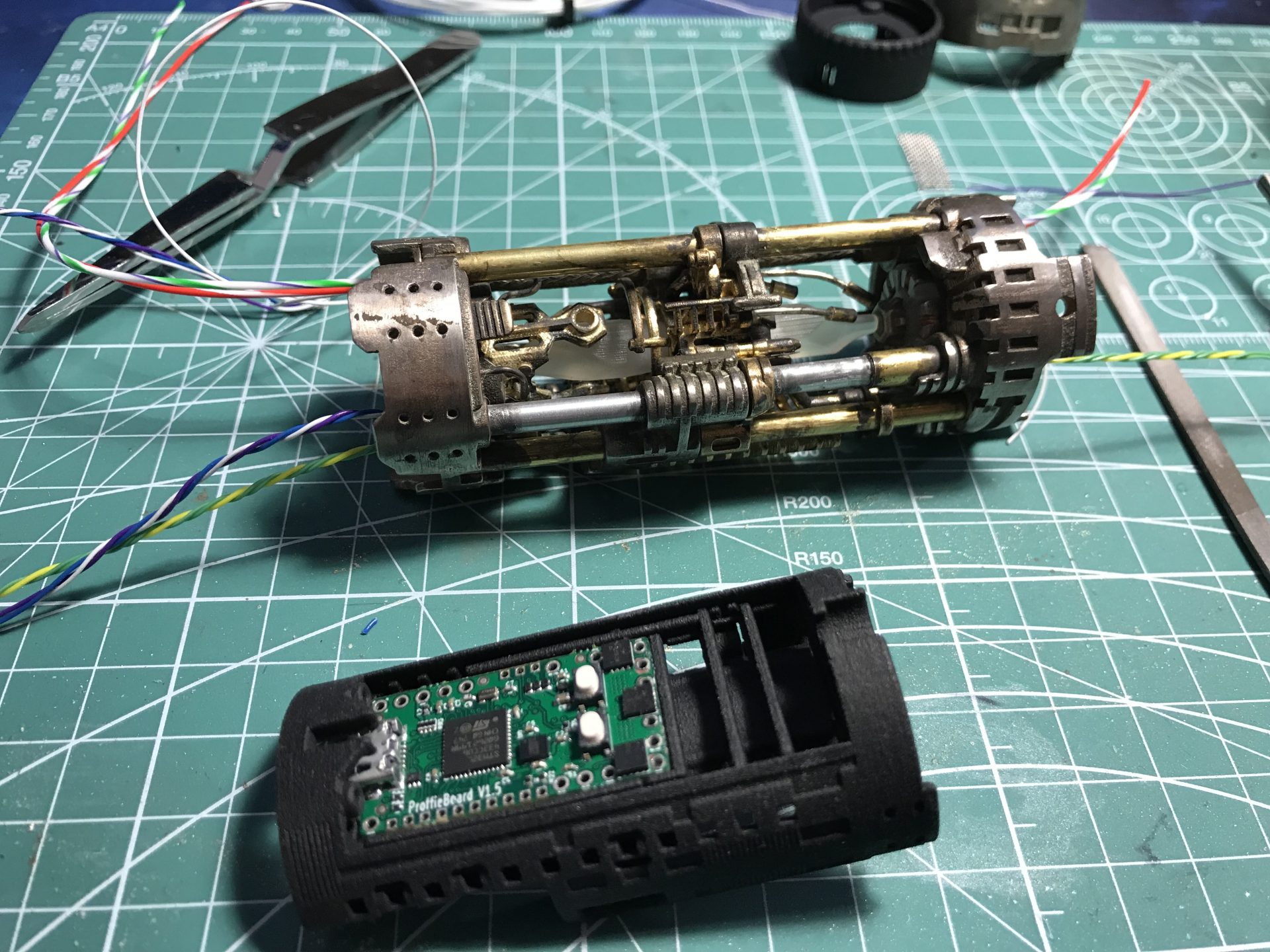
Step 24: Install the soundboard.
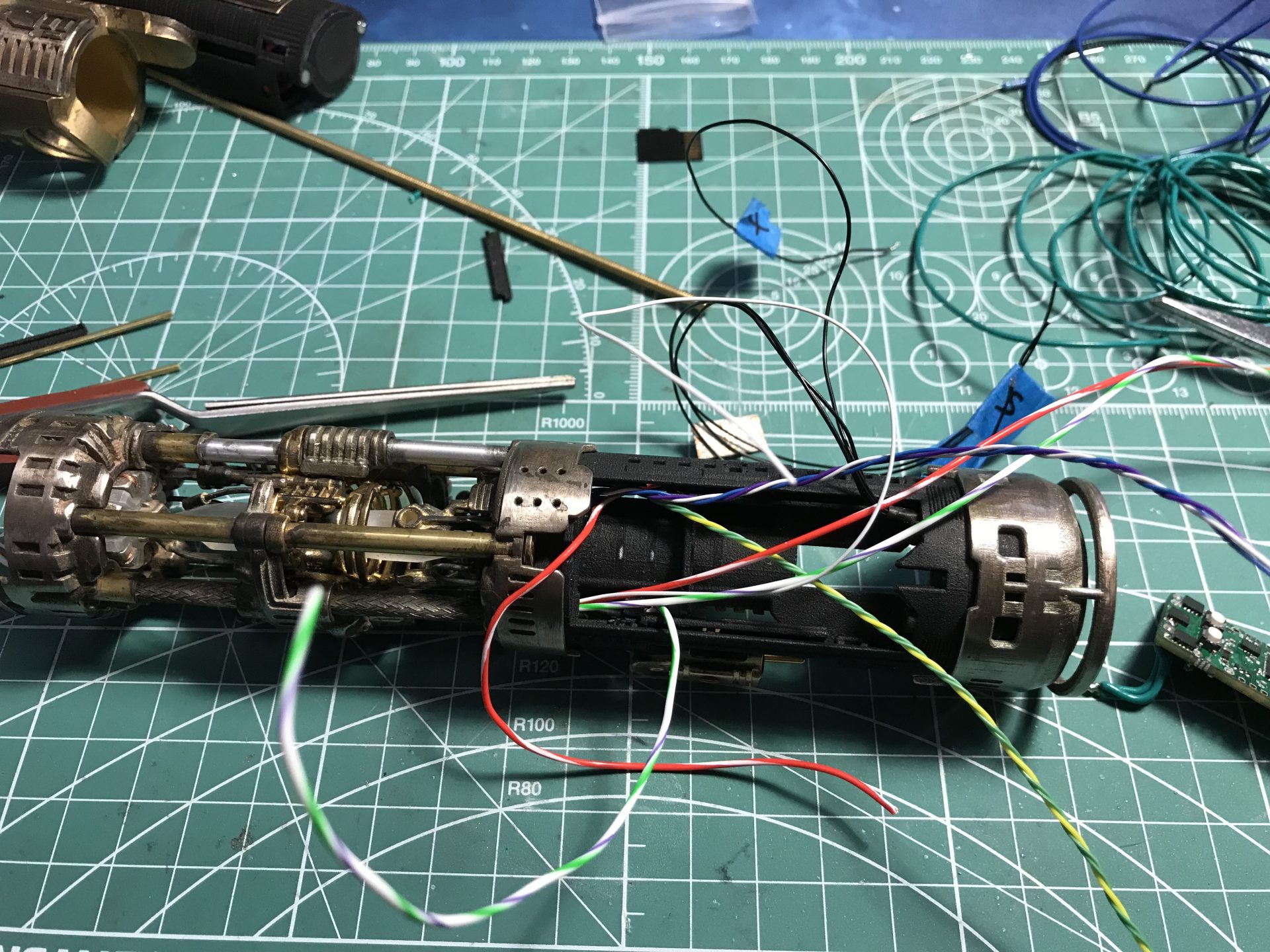
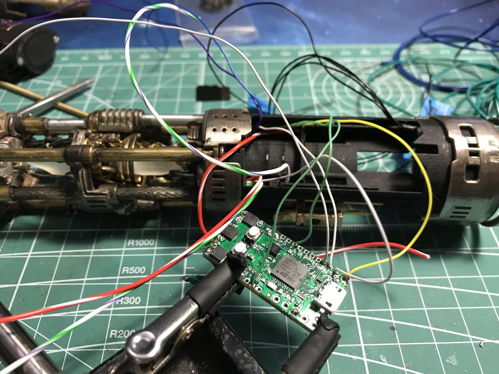
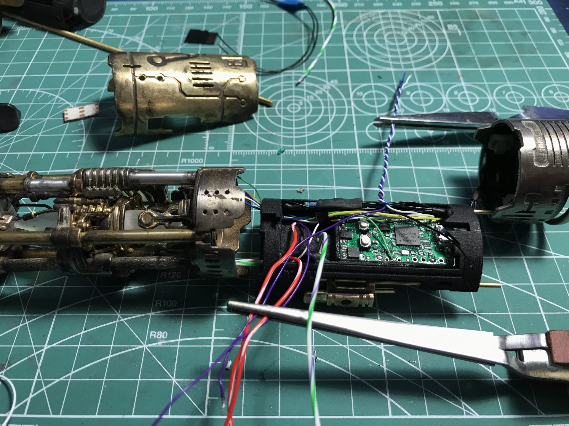
Additional leds can be installed on top of the soundboard (here we install Neopixel Subblades for ProffieBoard).

The back of part 8 also has holes for accent Leds (4 holes for 3mm accent leds, 1 hole for 5mm accent led) – not used on this install.
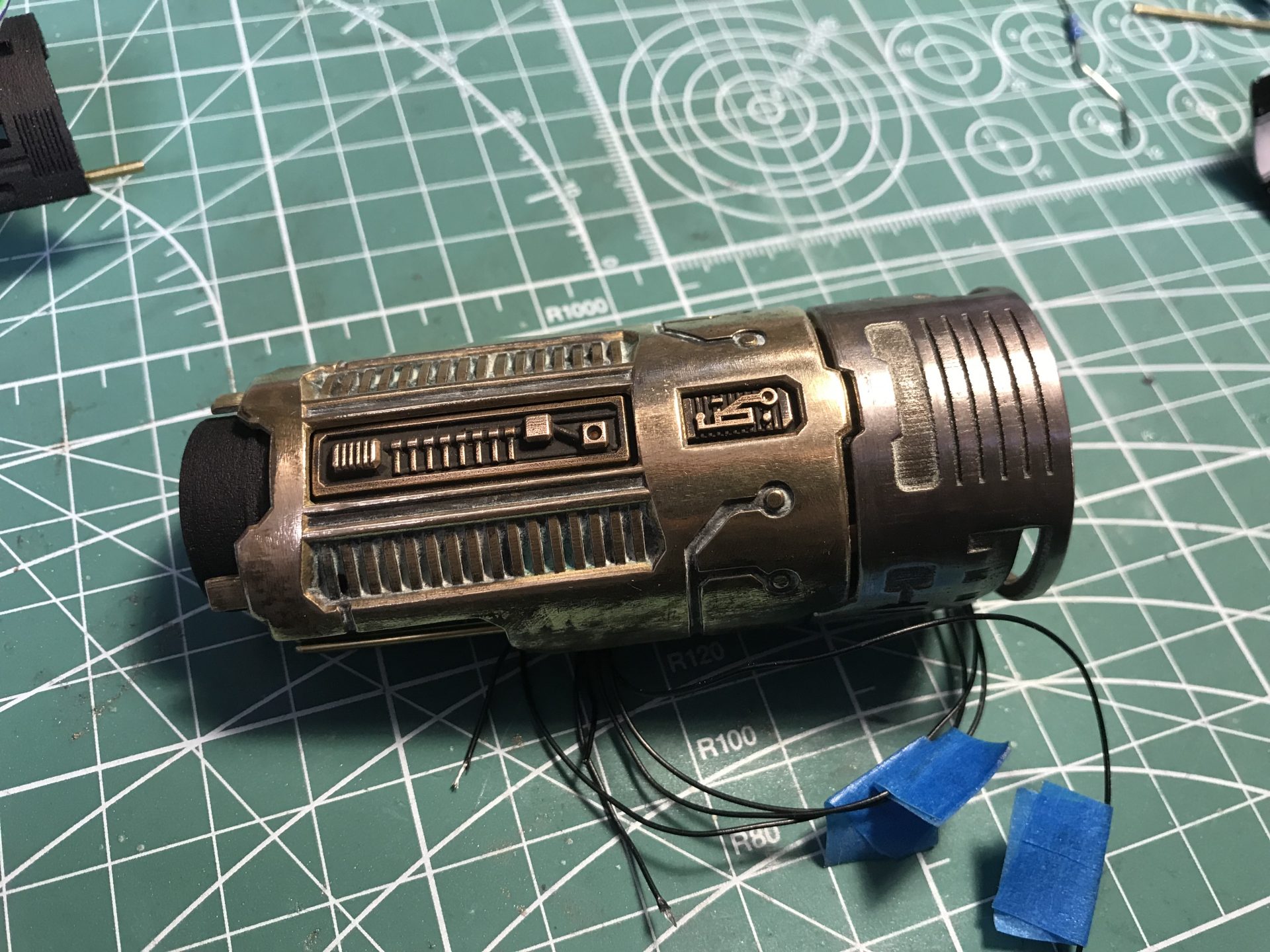
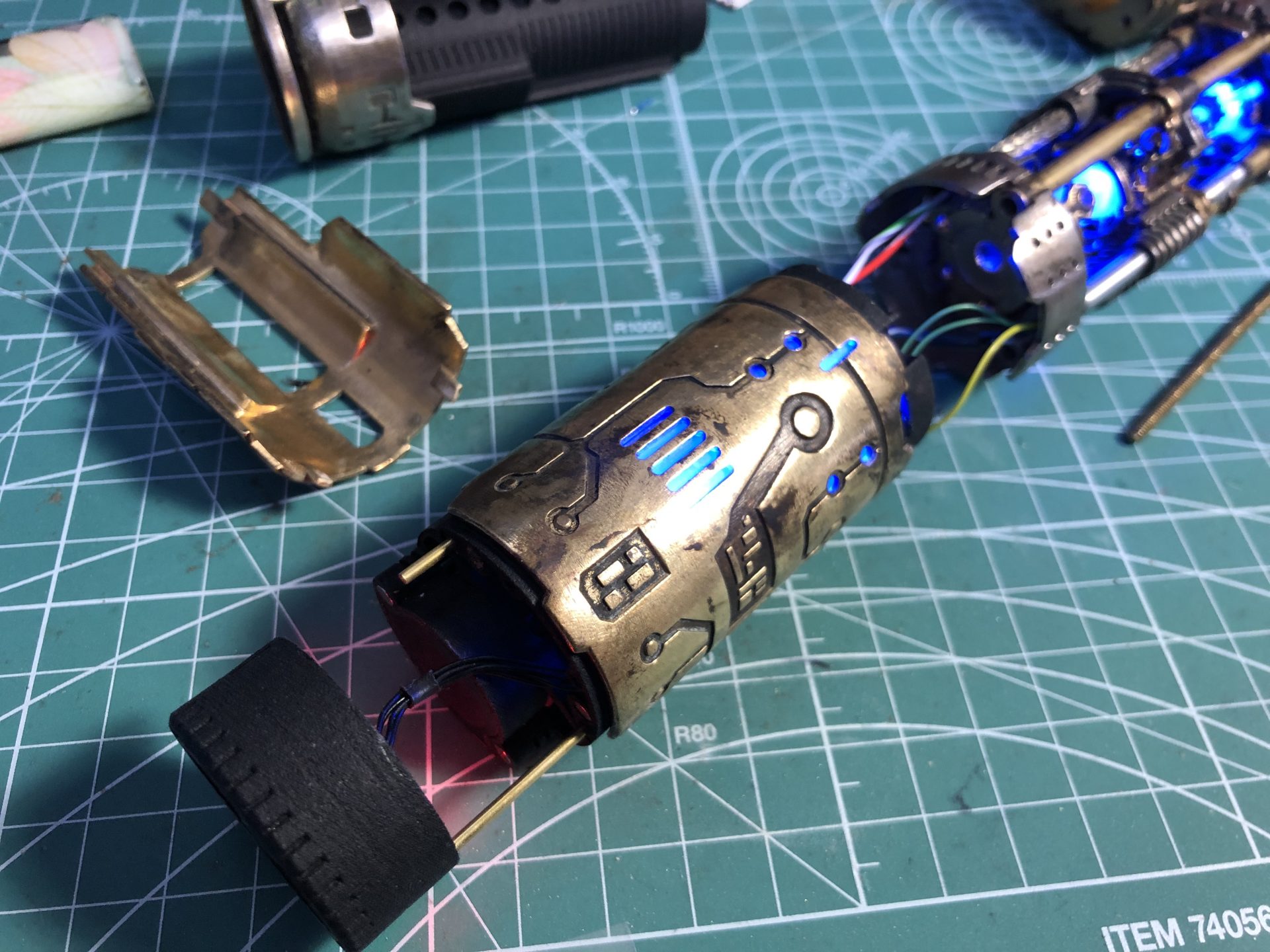
Step 25: For a better diffusion of light through the cover holes, frosted tape can be added.
Add the cover over the chassis and test.
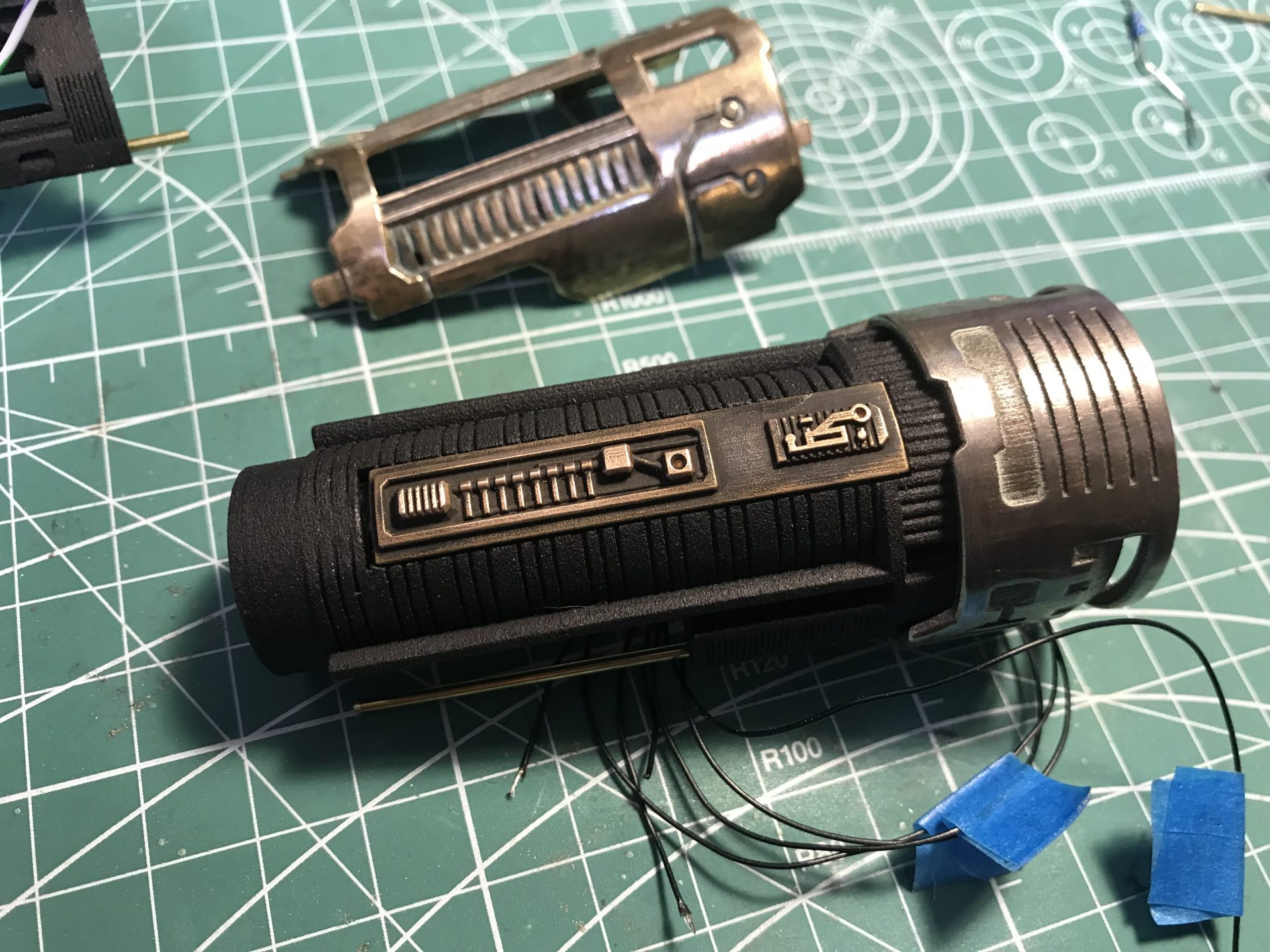
Step 26: Remove the cover a bit, U shaped 1.5mmOD rod can now be attached to the speaker holder. Then put the cover back in place.
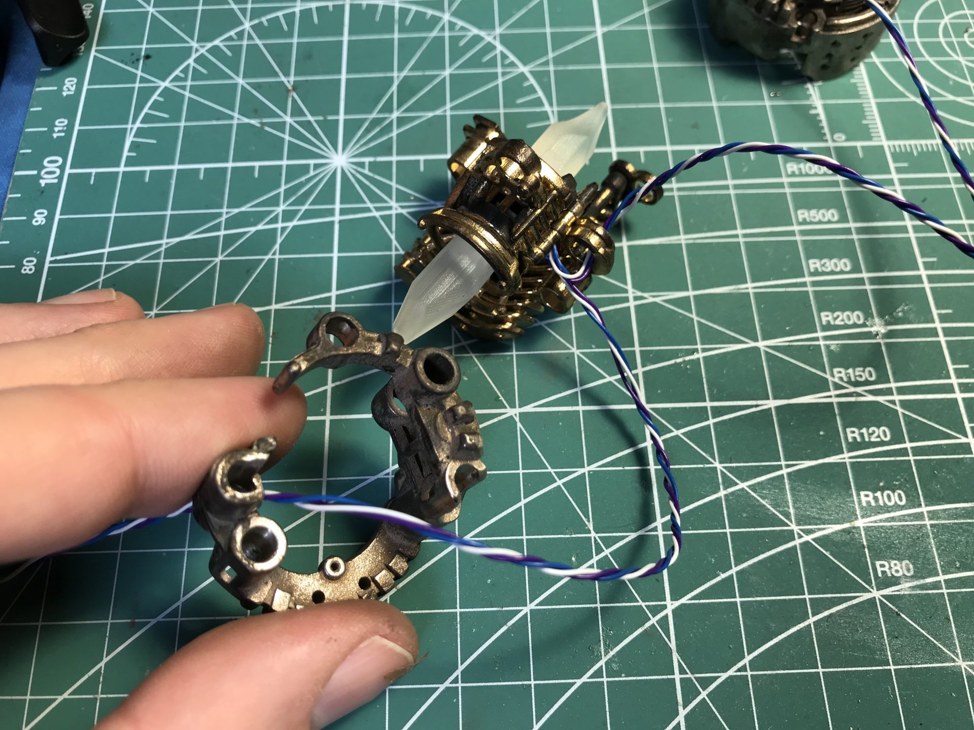
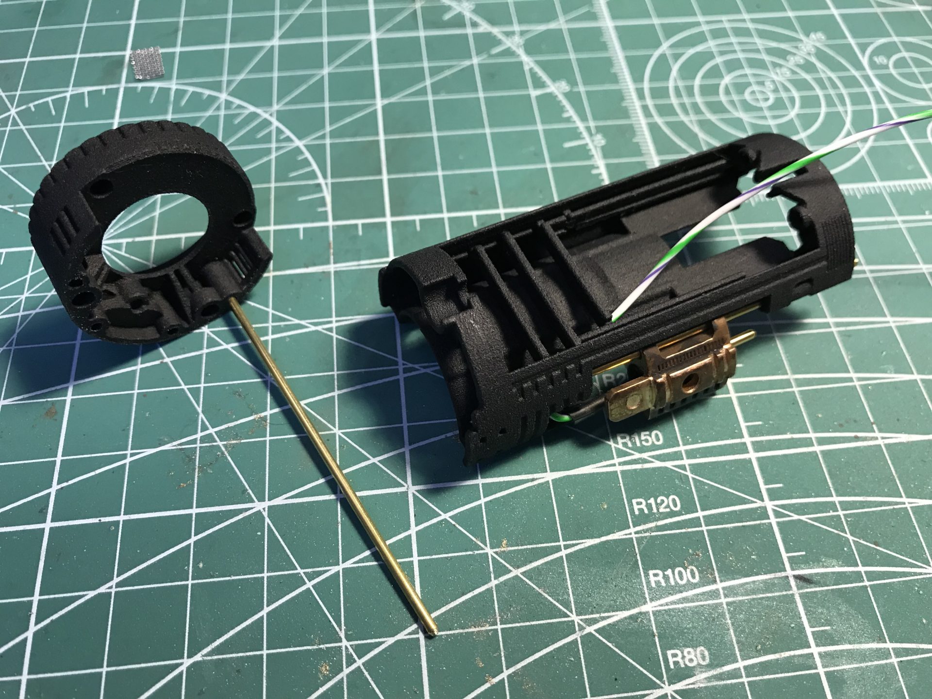
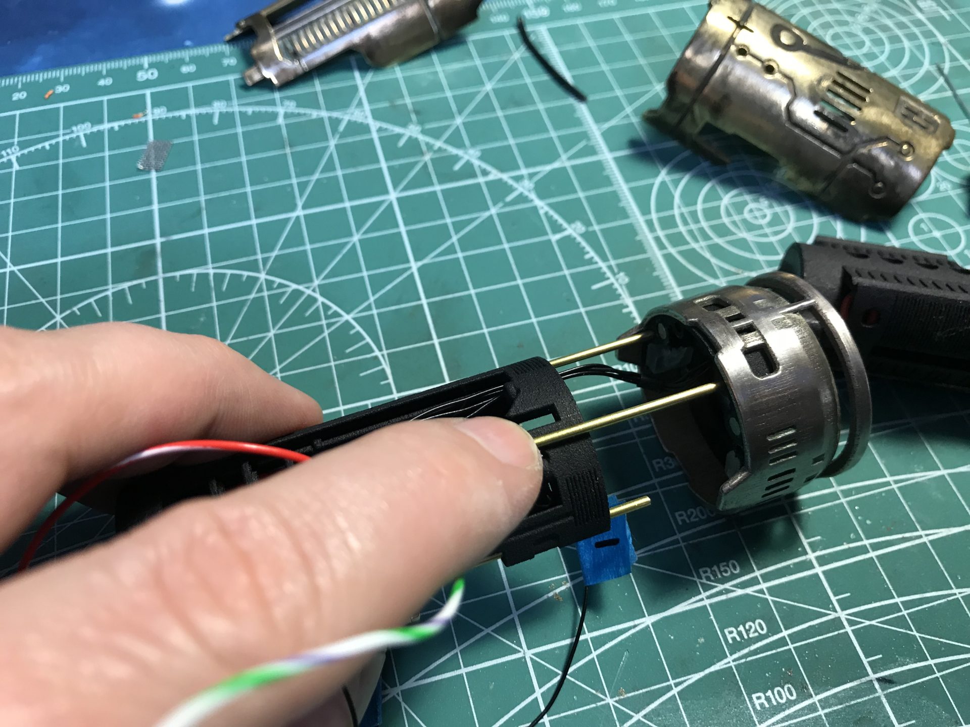
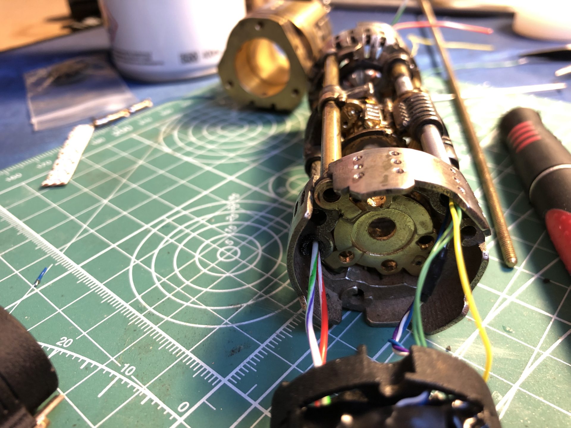
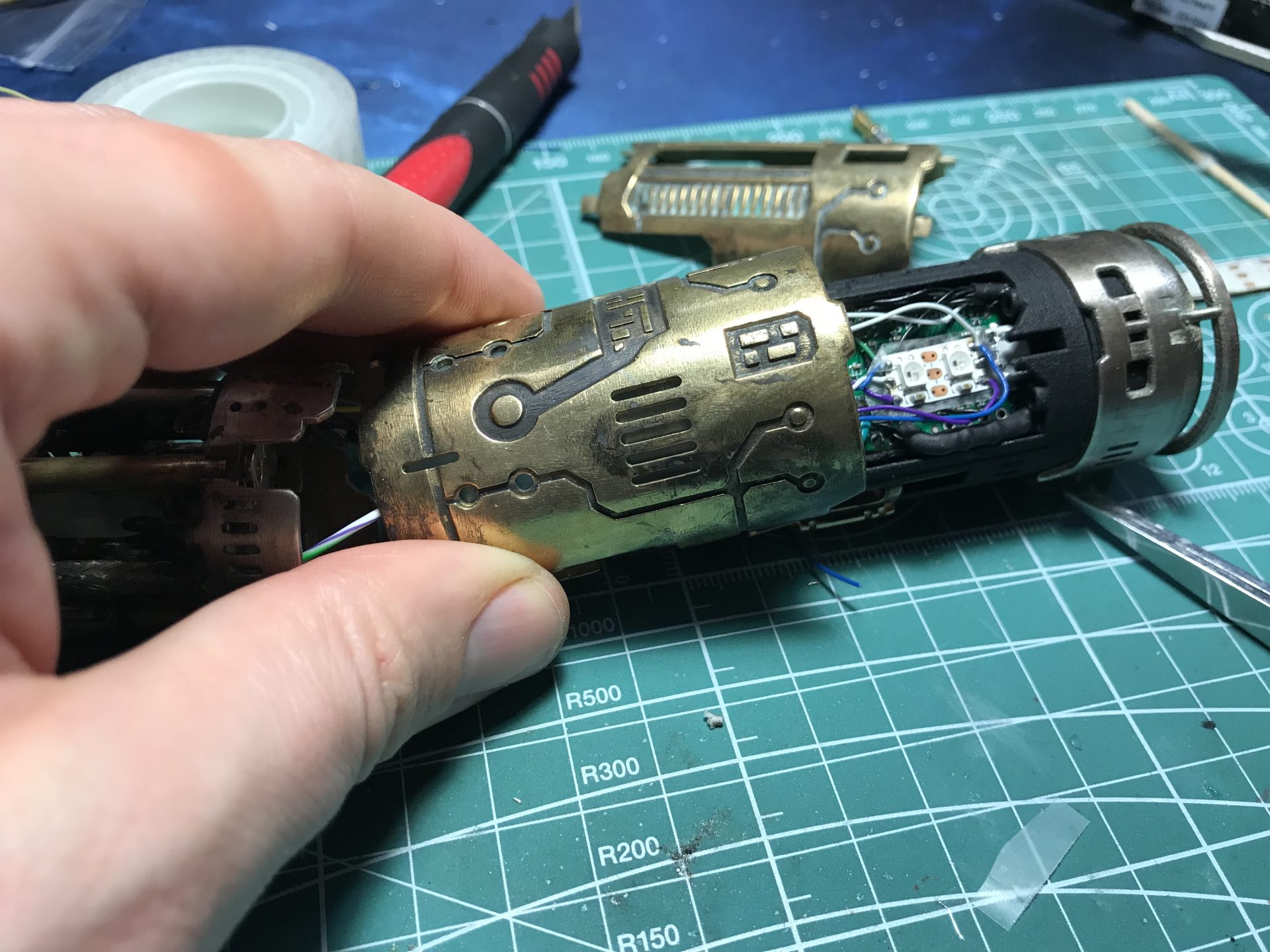
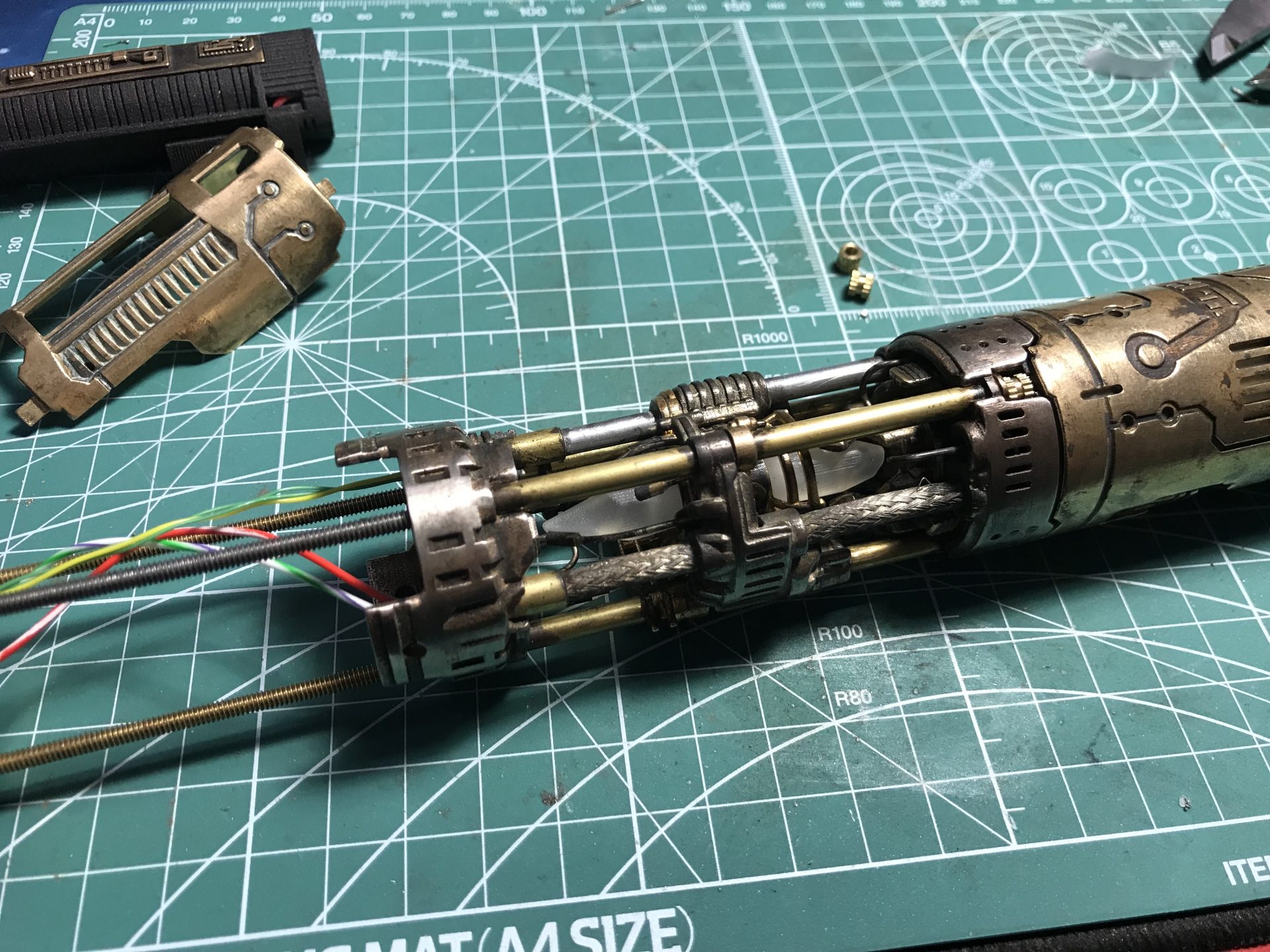
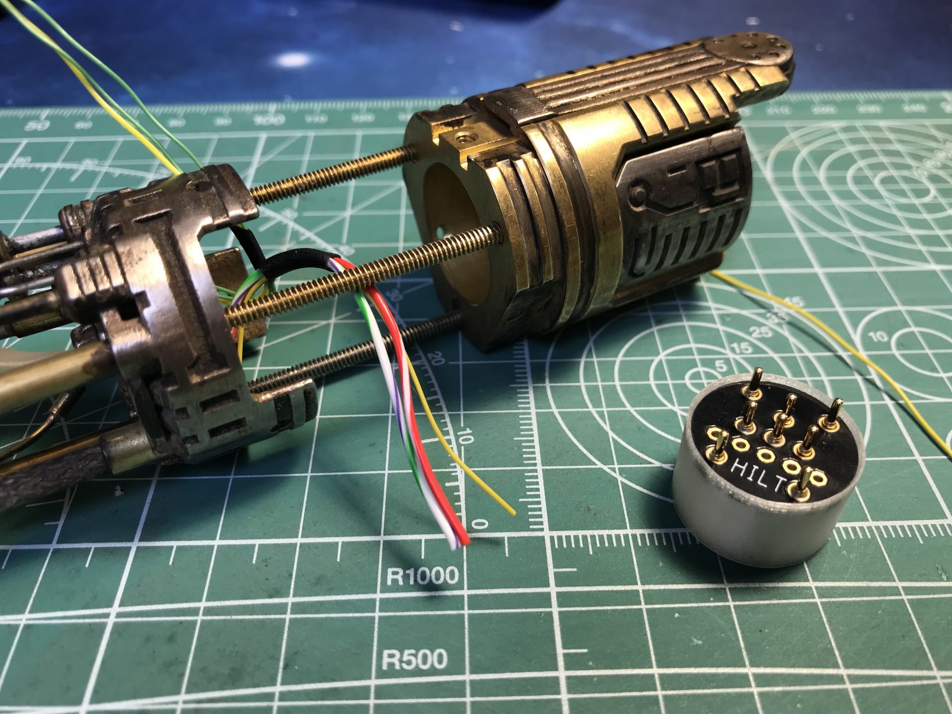
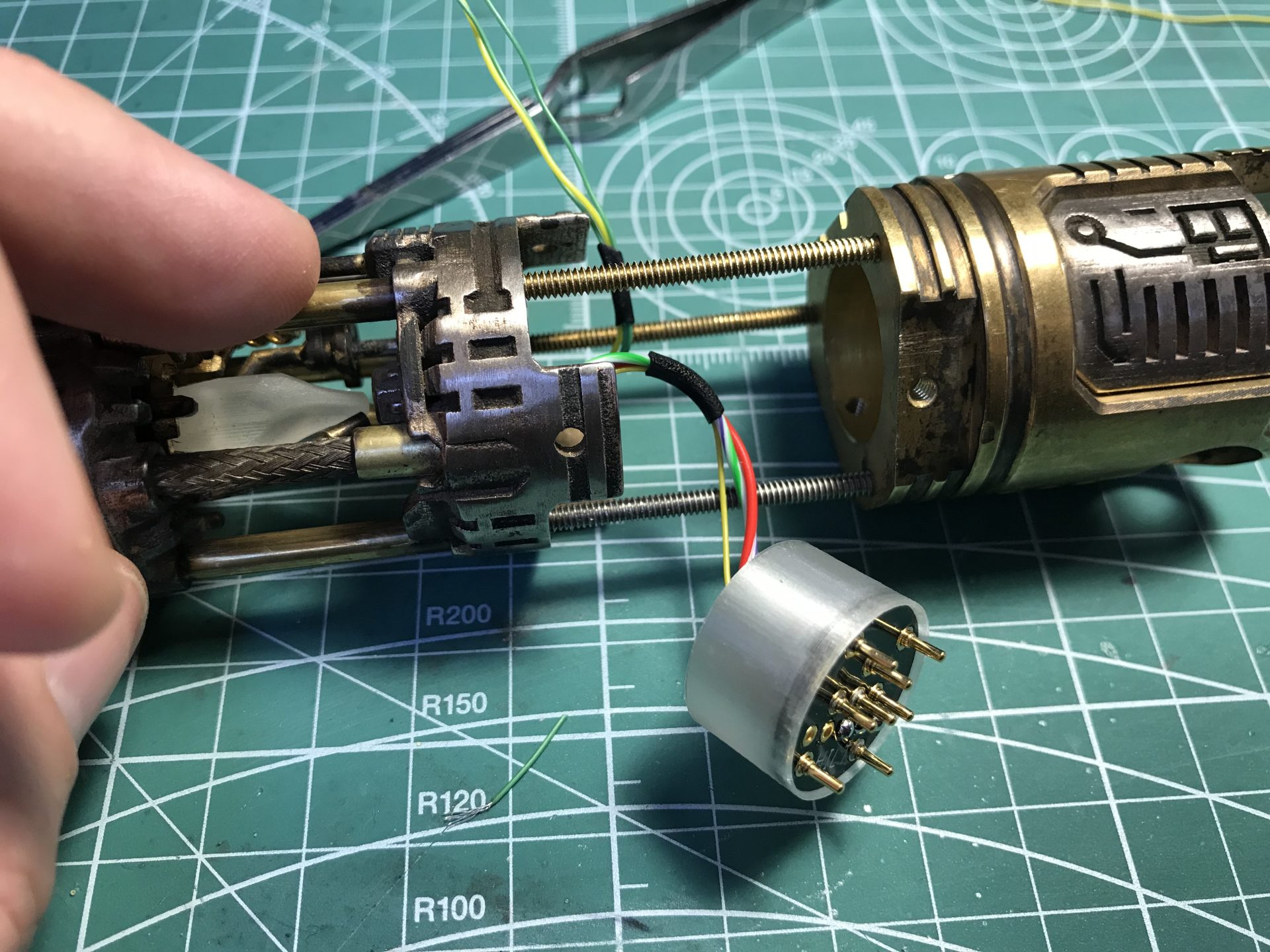
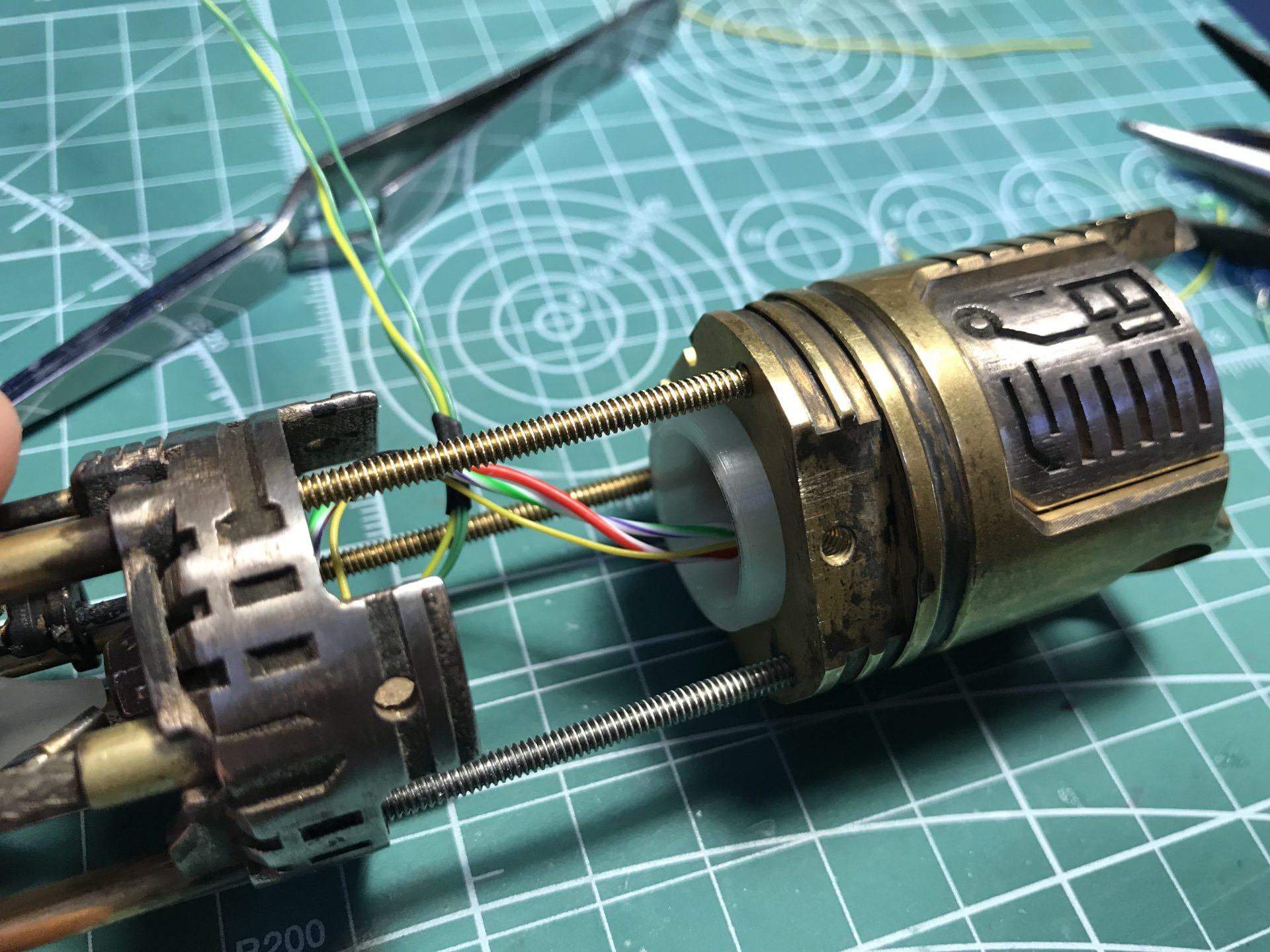
Step 27: Join the crystal chamber to the chassis. Pull up the wires on the emitter side while inserting the chassis.
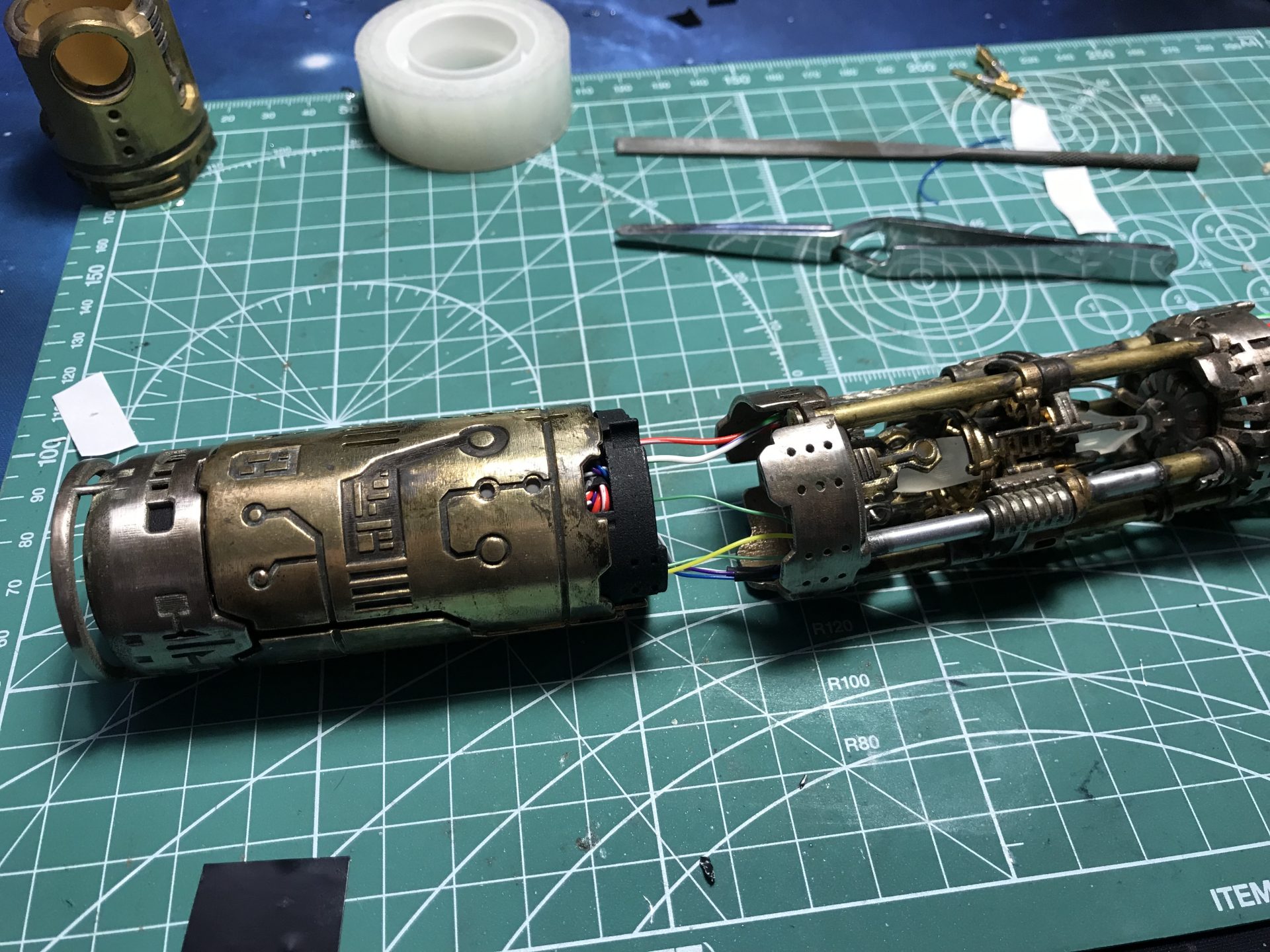
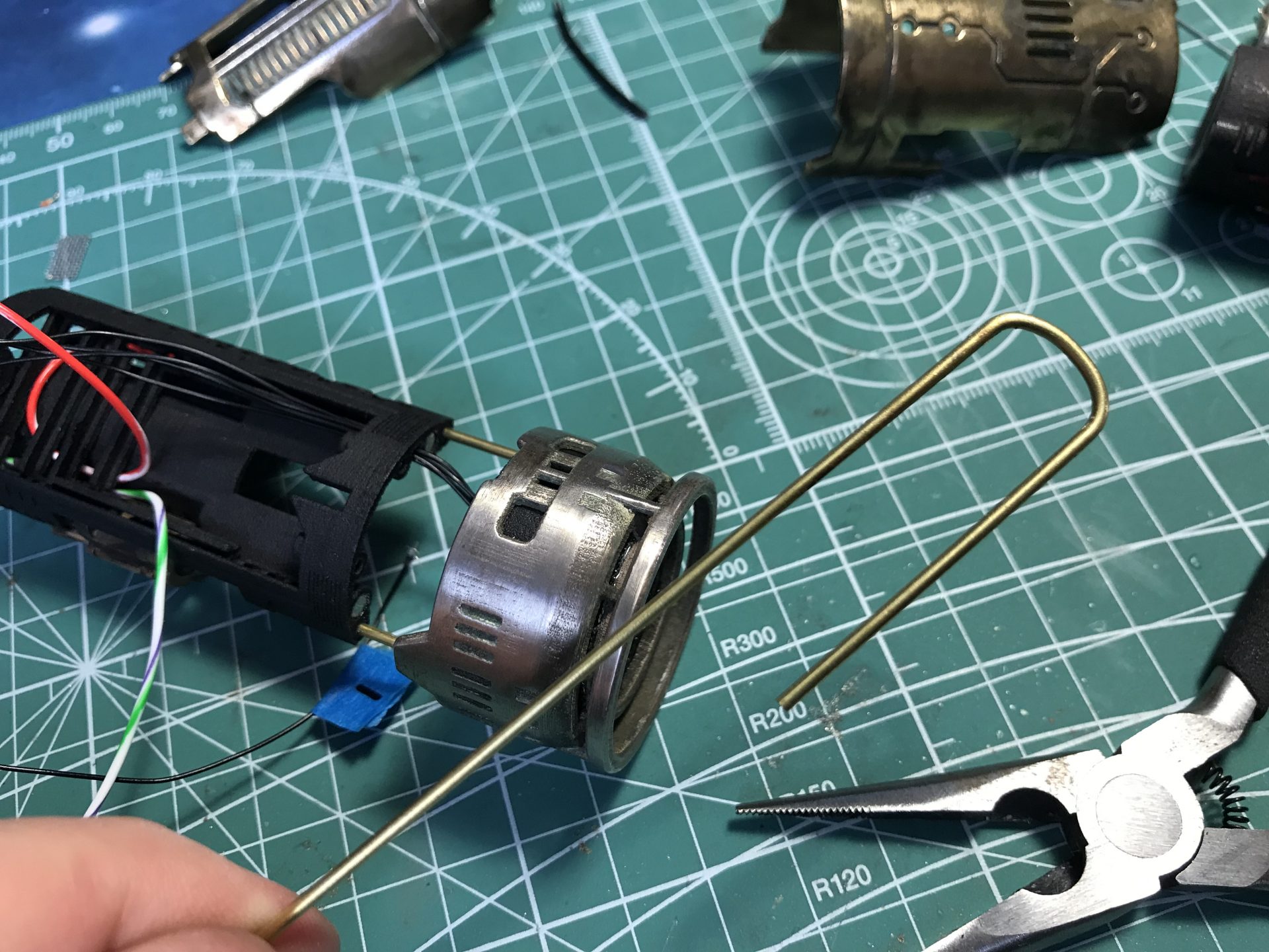
Next, as shown of the pictures, add 1mmOD rods to lock the chassis with the crystal chamber assembly. Do not insert the 1mmOD rods all the way in, it is important to leave some space, as it will allow the rods to be pushed in in case disassembly is needed.
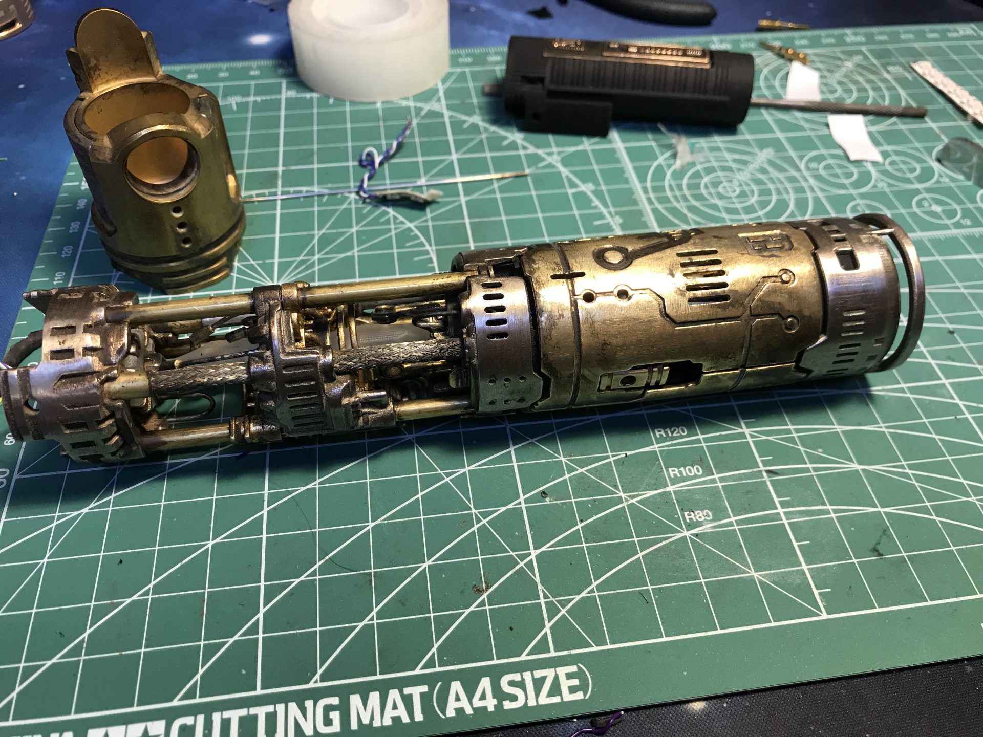
Sand down the rods. The chassis is now ready.
Step 28: Cut the 4-40 threaded rods, and add them to the blade holders.
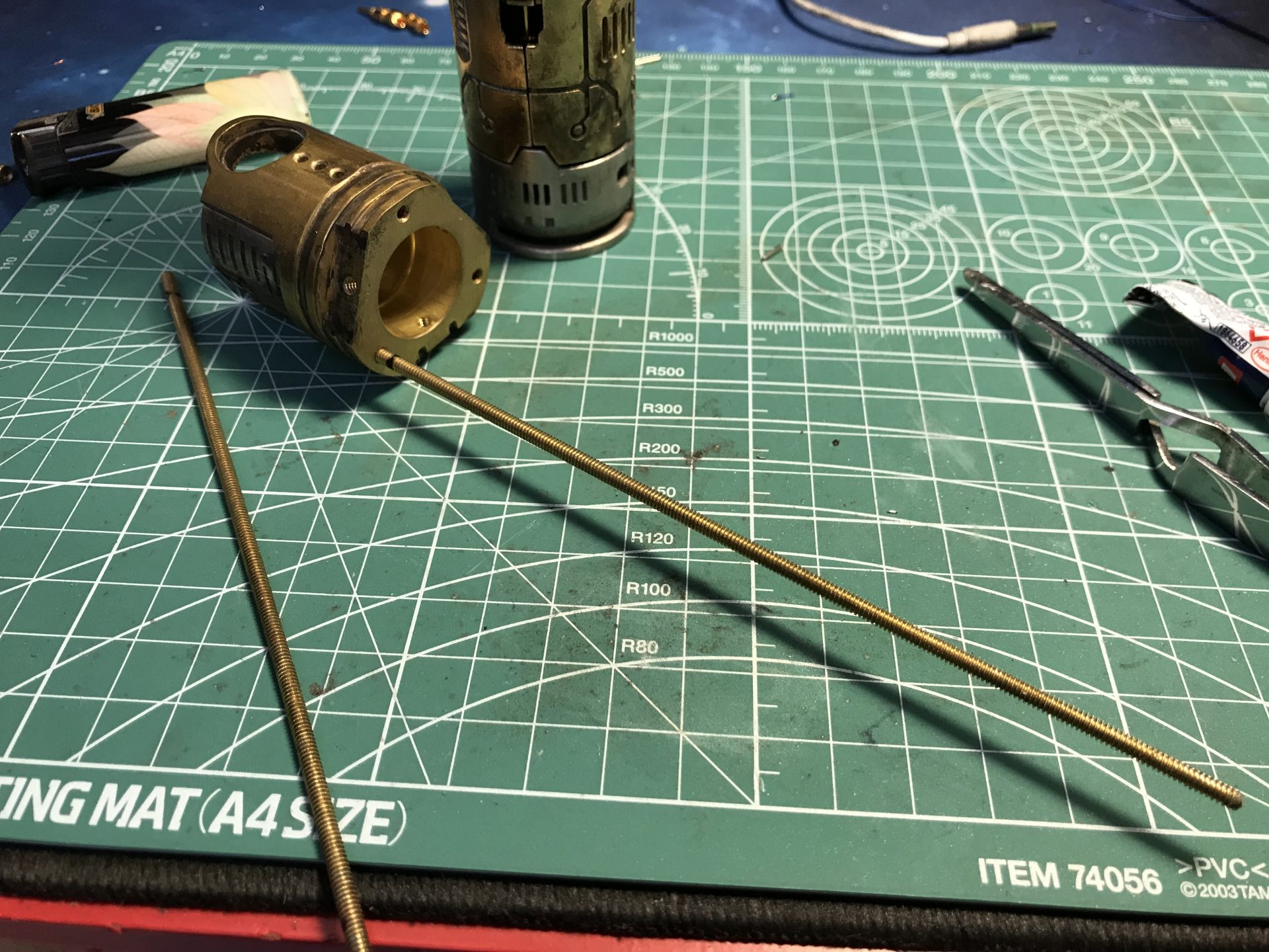
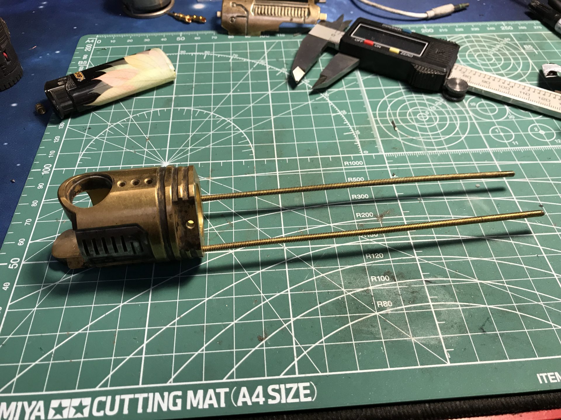
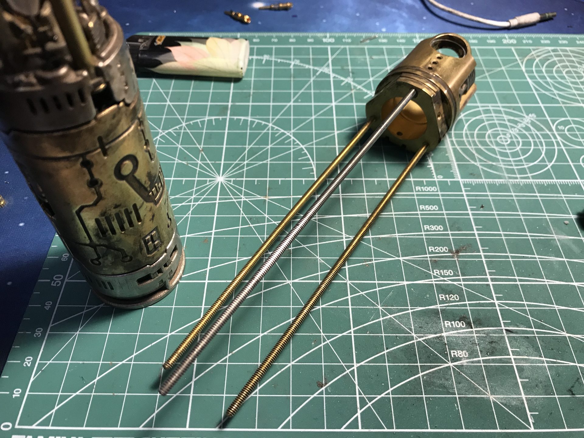
Test the fitment, and especially that the power cell can be removed. If not, shorter the to lower rods.
Step 29: Once tests are ok, the blade holder can be pushed up again, in order to add nuts to lock the assembly (the nuts are 4mm long).
Screw in the blade holder halfway through (to then add the Neopixel connector or main led).
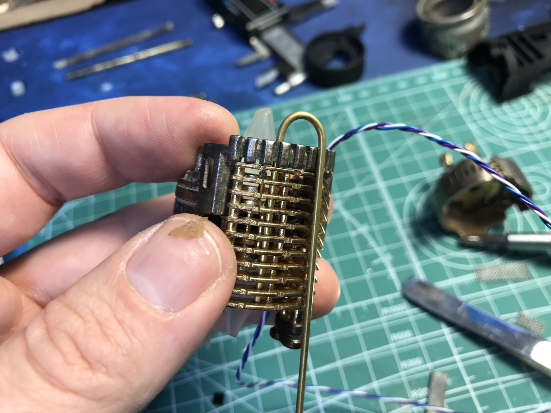
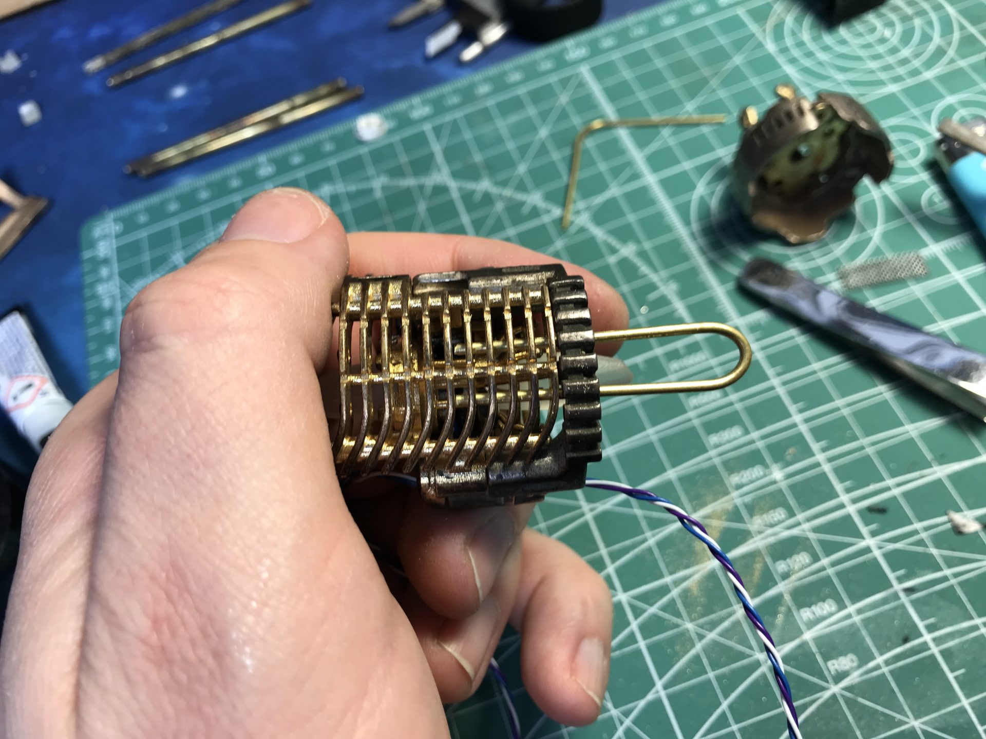
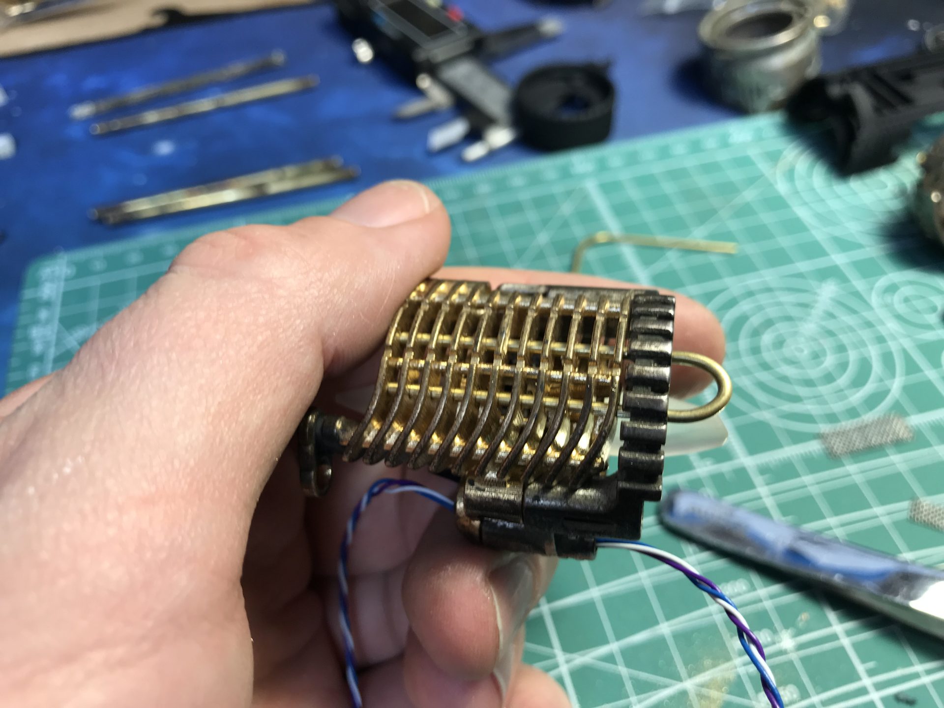
Step 30: Install the main led and heatsink, or neopixel connector.
Step 31: Switches install. The Aux switch uses 1.5mmOD rod to lock in place.
Make sure the main switch area is clean (especially if using steel. Then wire and add the brass tactile switch (we add nitto tape on the bottom for insulation).
Add the assembly back on the blade holder (wires go into the recessed area, as shown below).
Step 32: Finish to screw in the blade holder completely.
If NWL Master Blade Holder is used, there is another possible retention method. 4-40 retention screws can be used, or the rod left over can also be turned into a screw.
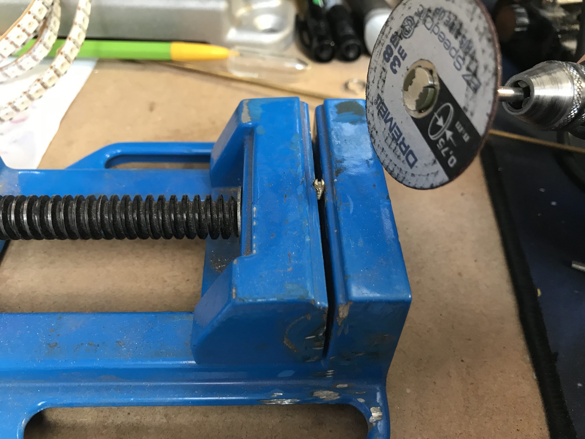
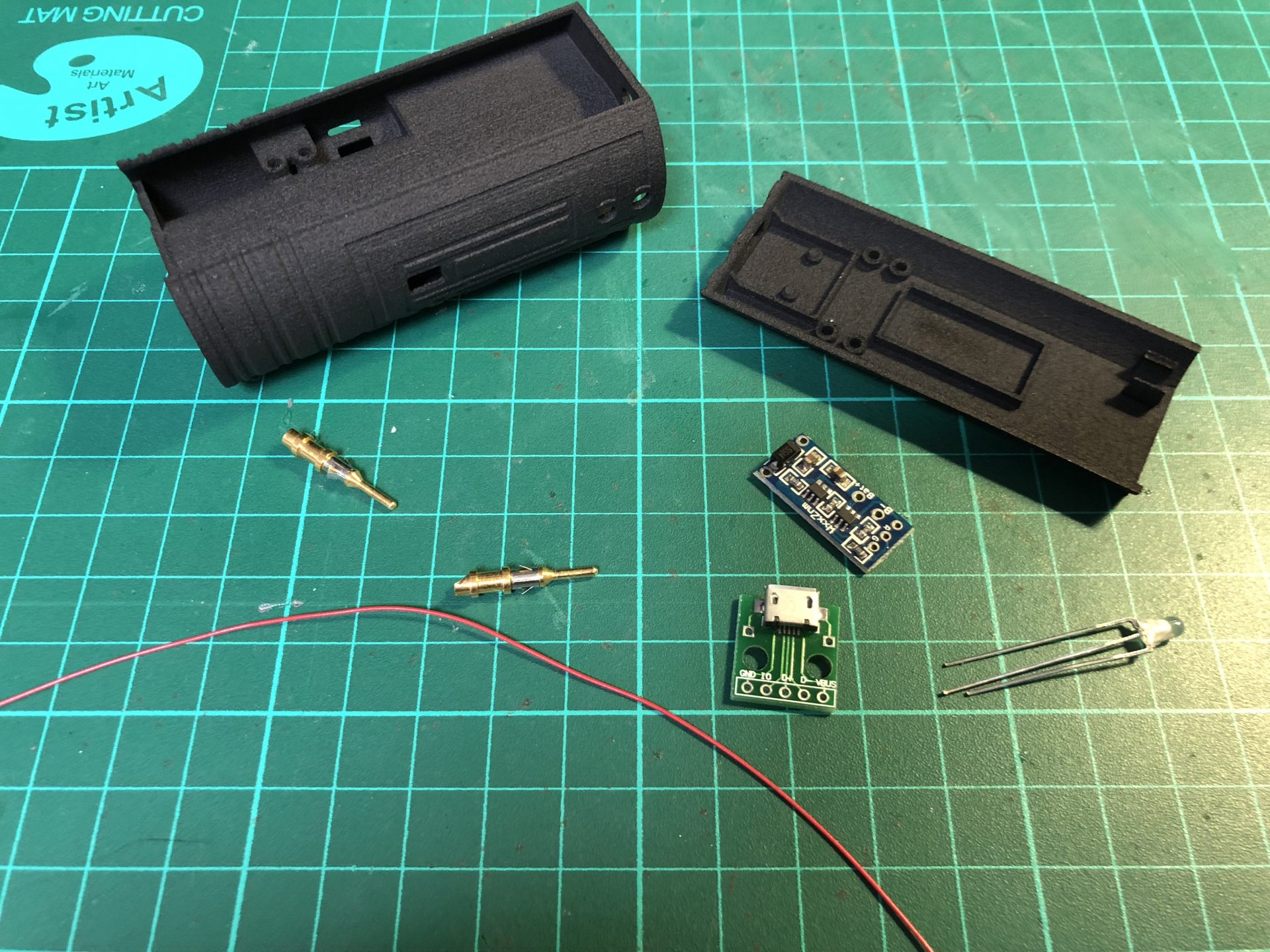
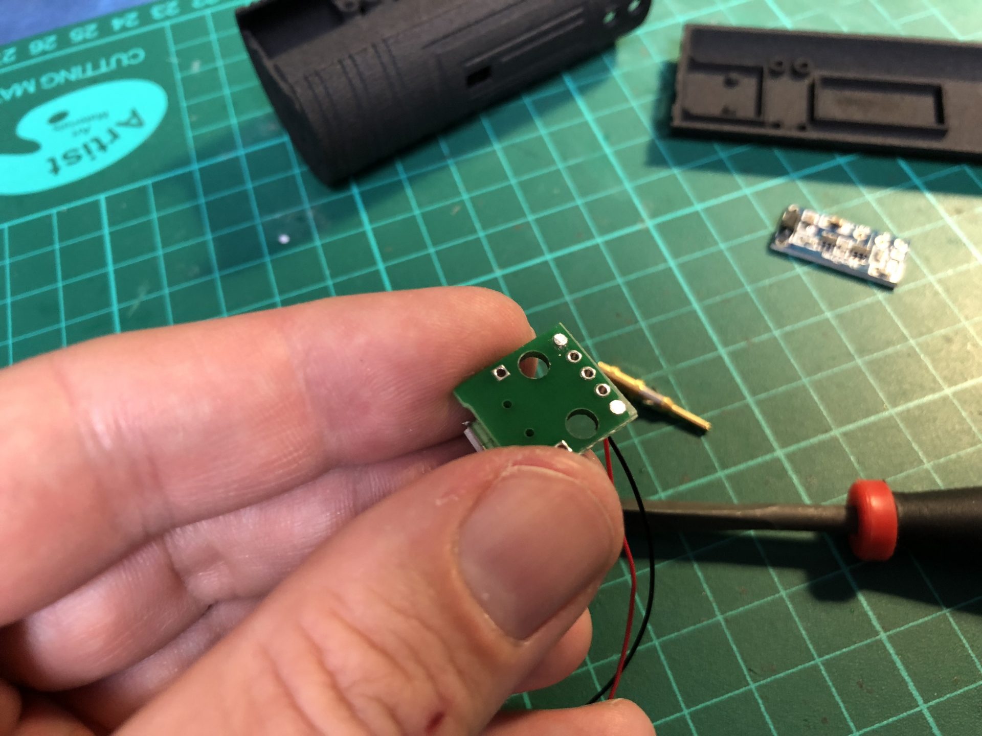
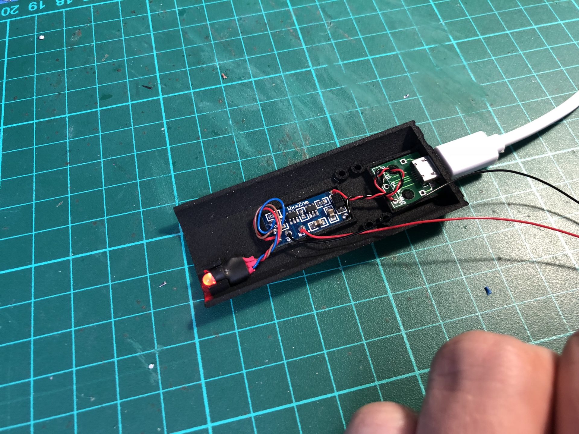
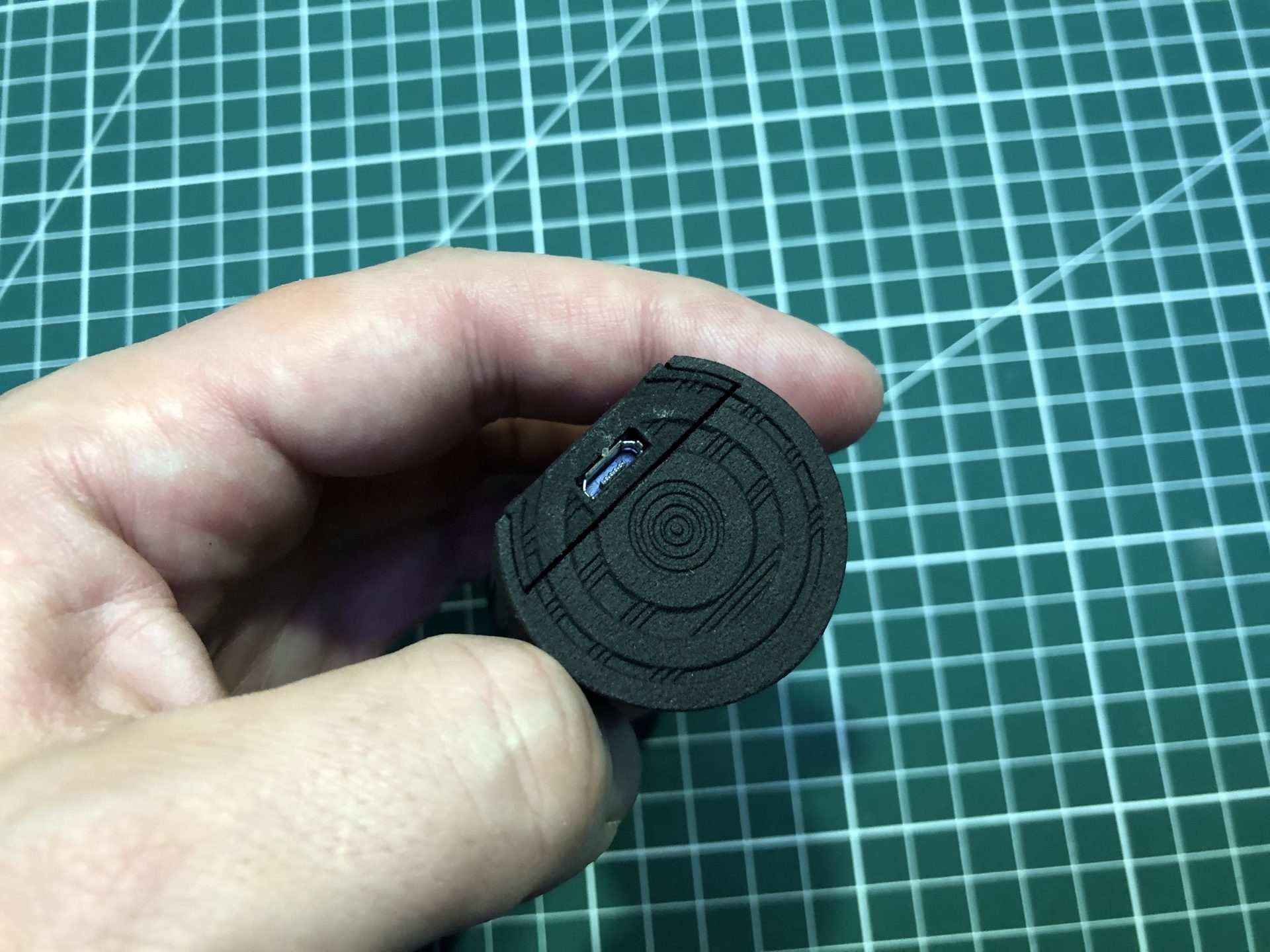
Step 33: Build the USB Power Cell charger.
Wire the Ground (neg) and VBUS (pos) pad on the usb PCB.
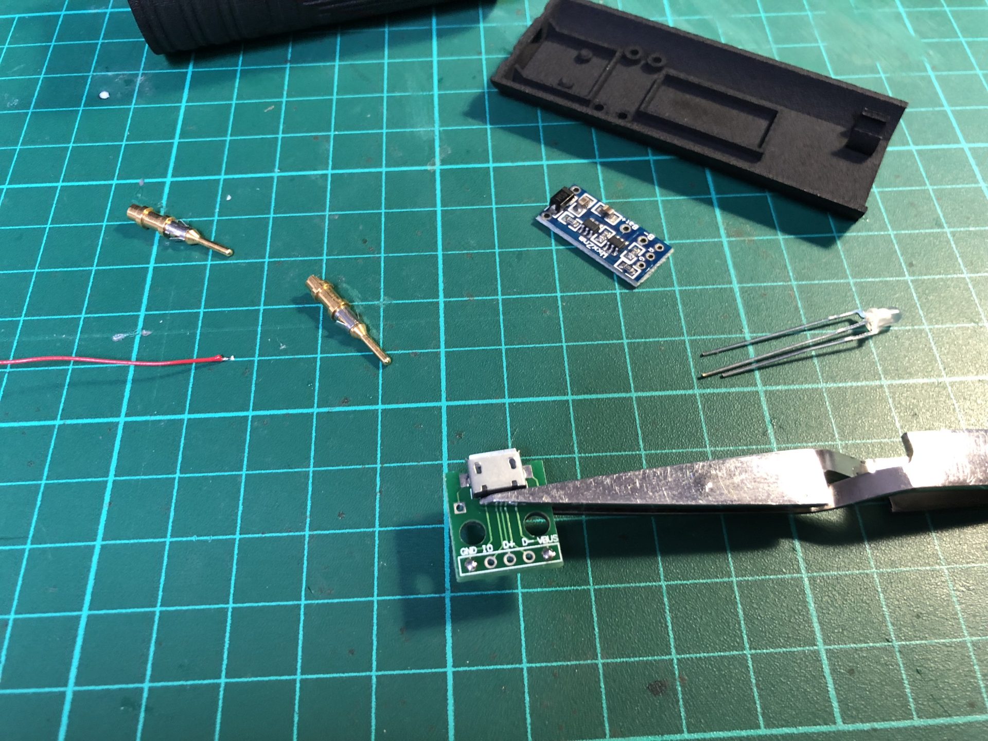
Make sure the bottom of the PCB is flat,
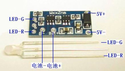
Neg and Pos wires are soldered on their respective pads on the charge module PCB as shown below.
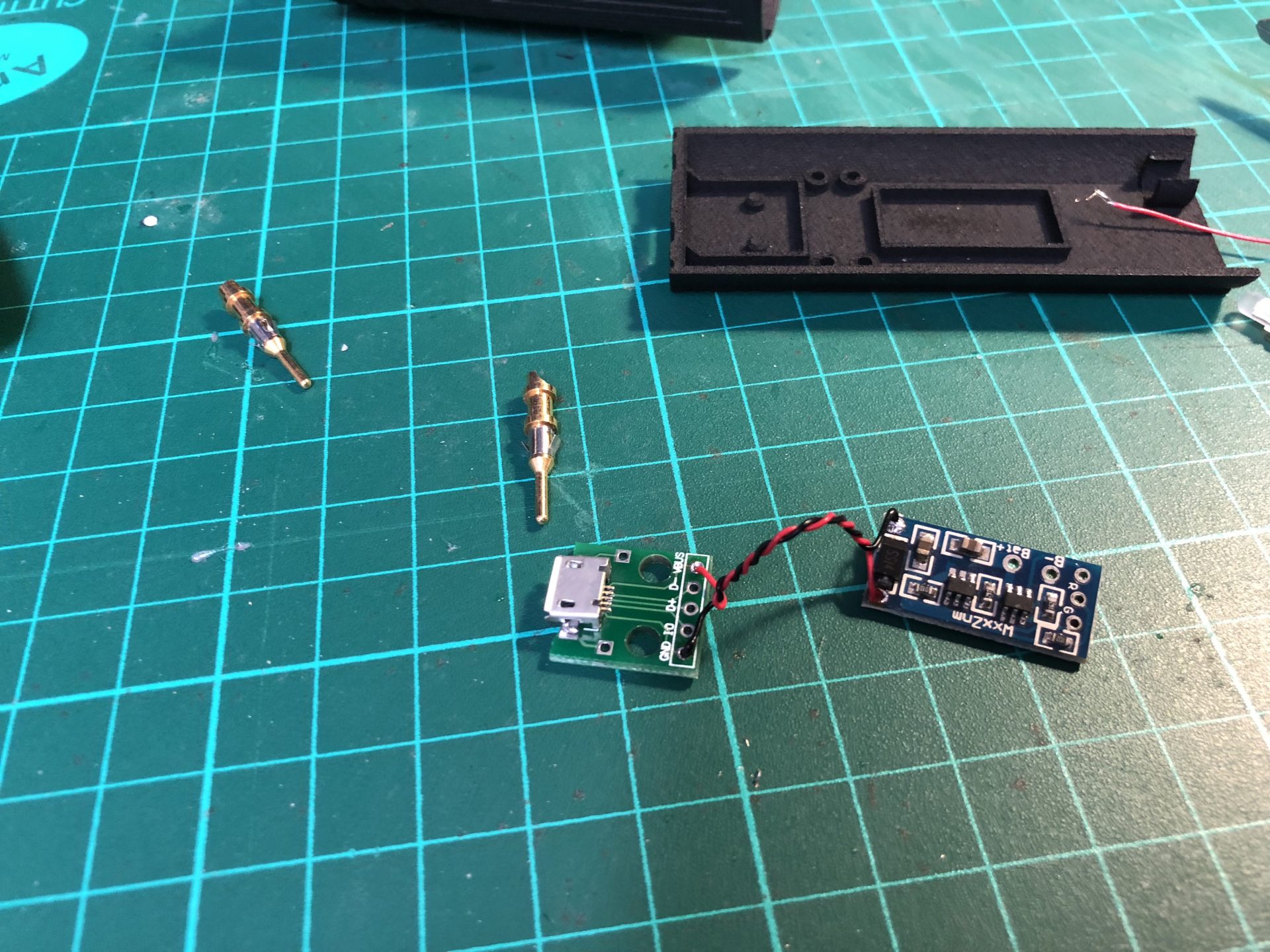
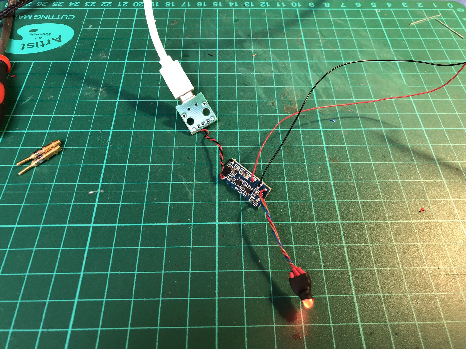
Then wire the led and the battery charging pins and glue the PCB on the chassis top (PCBs might require a bit of sanding on their side to fit correctly).
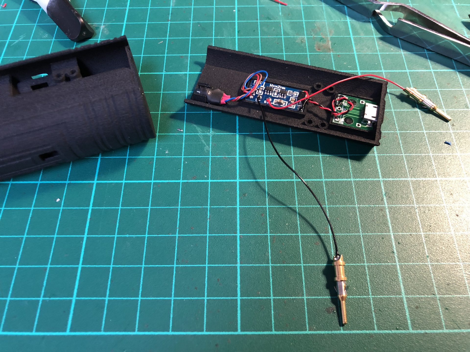
Insert the pins (making sure to respect the sides according to the battery) in the lower chassis.
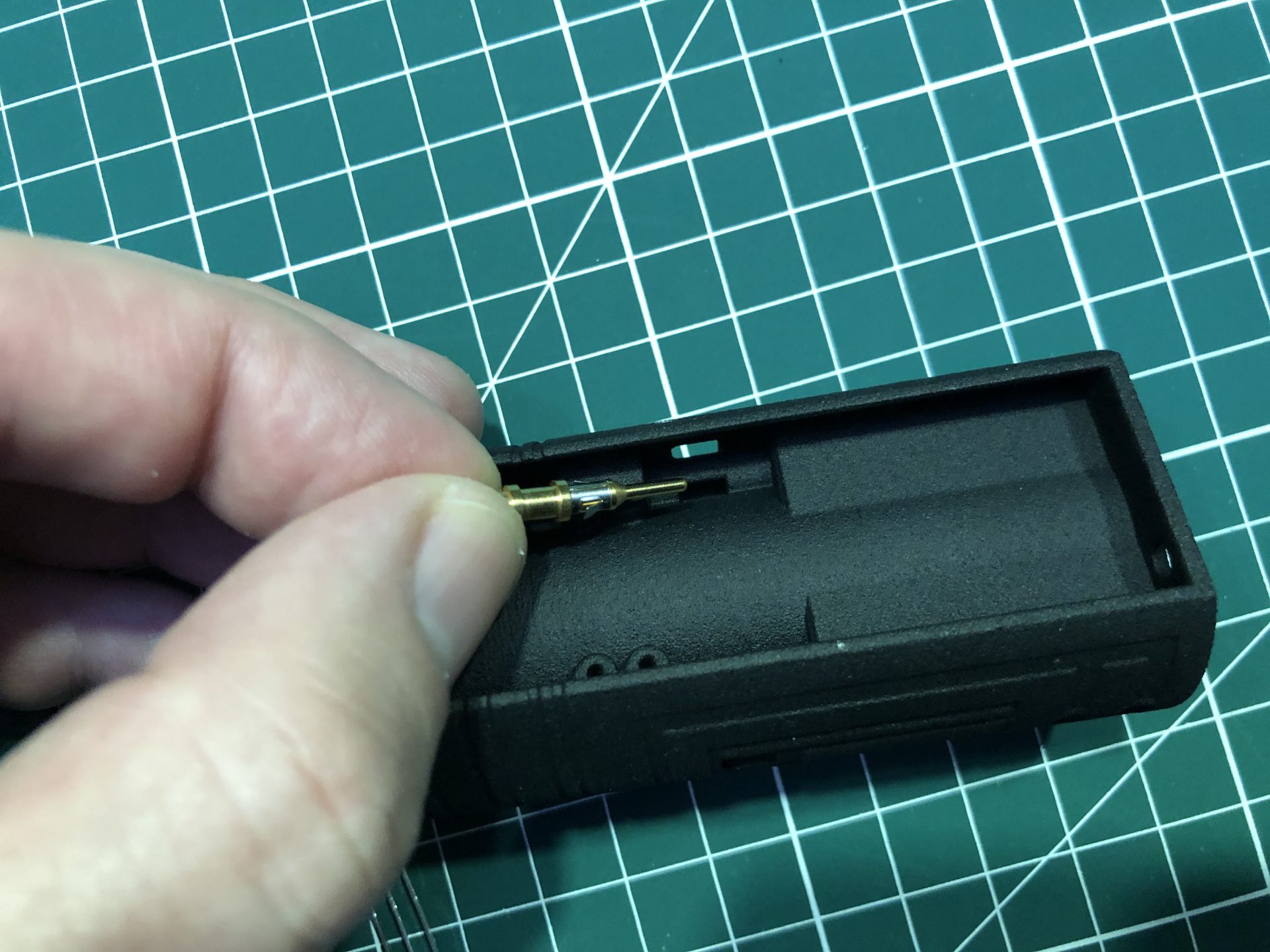
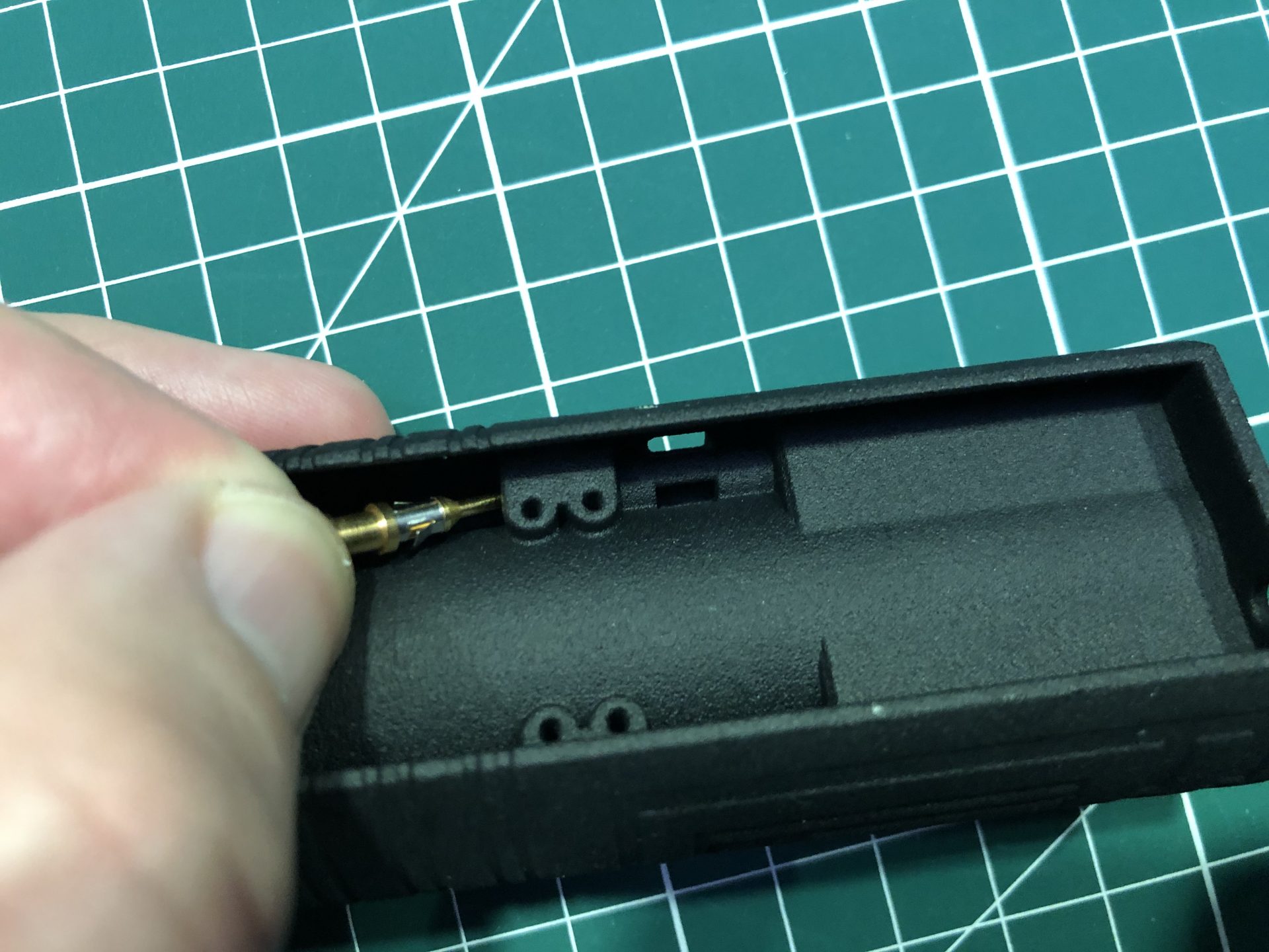
Join top and bottom chassis. There are 2 set od holes for 1.5mmOD rod to be added and lock the assembly (optional, both parts are press fit and might not require the rods)
All done!!